exacqVision Z Series User manual
Z Series 4U NVR Quick Start
Z Series 4U NVR Quick Start
www.exacq.com
www.exacq.com
3Establish Initial Communications
After installing the server, complete the following steps:
1. Using a directly connected keyboard, monitor, and mouse, configure the server’s networking connections:
a. After the eV Client software automatically starts on the server, expand the server device in the tree. Select System
Setup and then the Network tab.
b. For servers with multiple interfaces, select the appropriate NIC port from the drop-down menu at the top of page:
i. If the server is installed on a network using static IP addressing (recommended), select Static, enter the
appropriate settings, and click Apply.
ii. If the server is installed on a network using DHCP (not recommended), select Dynamic and click Apply. After a
brief delay, all four parameter boxes should auto-fill with valid network settings. If not, contact your network
administrator for resolution.
c. Repeat this step for any additional network ports.
2. If the server will be configured through a remote eV client instead of the server, install the client software:
a. Download the latest eV Client software from the Exacq website at
http://downloads.exacq.com/downloads/exacqVisionClient.exe
b. Install the client software on a system administrator computer.
c. Confirm connectivity with the server using the ping command and server IP address. If the client PC cannot
communicate with the server, contact the network administrator.
3. If a remote eV client is being used, add the server into the eV Client configuration:
a. On the system administrator PC, start the eV Client software.
b. Select the Config (Setup) page button.
c. In the system tree, select Add System.
d. Click New and enter the username admin, password admin256, and IP address (static) or hostname (fixed)
configured in previous steps.
e. Click Apply.
i. If the new server appears in the system list table with a status of Connected, the initial server configuration is
complete.
ii. If the server does NOT connect, but server connectivity was confirmed in previous steps, confirm the PC anti-
virus software is not blocking communications with the server IP addresses and ports.
4. Change the default operating system and exacqVision admin and user account passwords:
See www.exacq.com/kb for instructions on changing the operating system password on exacqVision servers.
See Chapter 4 of the exacqVision user manual for instructions on changing exacqVision admin and user passwords.
5. Proceed to the software configuration steps found in the software user manual. The manual can be downloaded from the
Exacq website at http://www.exacq.com/support/specsheets.html.
©2014 ExacqTechnologies #500-00047
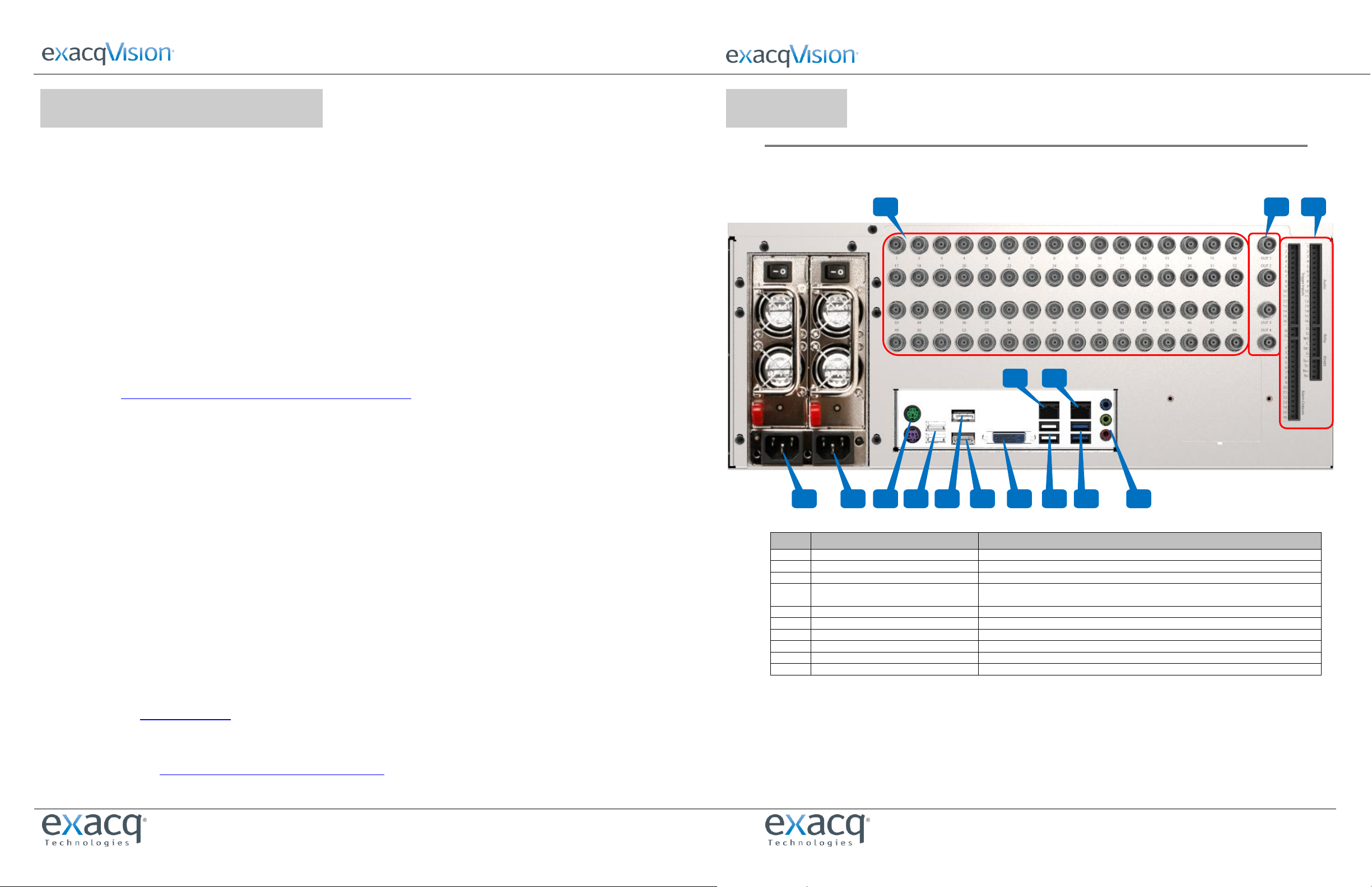
1Connections
MAIN BACK PANEL CONNECTIONS
(Hybrid System shown; see table to identify connectors not included on IP Systems)
Item #
Description
Notes
1
Power
100-240VAC 50/60Hz (connect 1a and 1b to separate power circuits)
2
PS/2 connectors (two ports)
PS/2 keyboard and mouse
3
USB 2.0 (two ports)
USB keyboard, mouse, memory device, or DVD burner
4
Video out (three ports)
DisplayPort (4a), HDMI (4b), DVI-I (4c)
A maximum of two video outputs should be used simultaneously
5
USB 2.0/3.0 (four ports)
USB keyboard, mouse, memory device, or DVD burner; USB 2.0 (5a) and USB 3.0 (5b)
6
Audio in/out
Line in (blue); line out (green); microphone (pink)
7
10/100/1000 Ethernet (two ports)
Dual on-board NICs (7a and 7b)
8
Video In
Hybrid Systems only; inputs and looping outputs; or inputs 1-64
9
Video Out (up to 4)
Hybrid Systems only
10
Auxiliary Connections
Hybrid Systems only; see detail on next page
1a
2
4a
6
9
8
10
1b
4b
5b
3
4c
5a
7a
7b
Z Series 4U NVR Quick Start
Z Series 4U NVR Quick Start
www.exacq.com
www.exacq.com
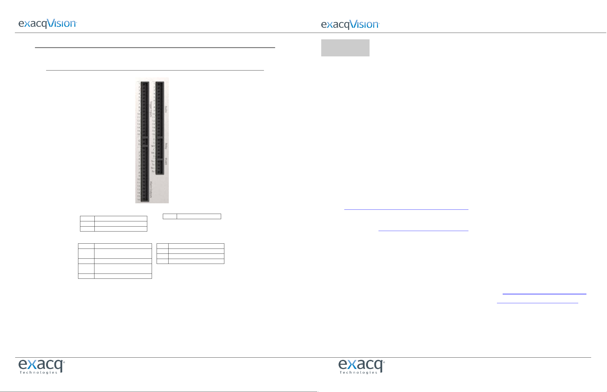
AUXILIARY CONNECTIONS
Hybrid Systems only
2Installation
Before starting the exacqVision (eV) server, complete the following steps:
1. Mount the eV server in a dust-free, climate-controlled (<70oF, <40% non-condensing) location. Dust can be ingested
into the server, causing component overheating. Elevated temperatures contribute to premature hard drive failures.
2. If the hard drives were shipped outside the system, insert each drive into the appropriately numbered hard drive slot.
3. Connect the eV server to a true online UPS for maximum reliability. A true online UPS completely filters power surges
and dips that can damage the server.
4. Connect the eV server network interface cards (NIC) to the appropriate network switch ports.
NOTE: If the video surveillance system does not have a physically isolated network, it’s recommended that all IP cameras
and one server NIC be connected to a dedicated camera VLAN. The camera manufacturer’s software should be installed on
a PC in this subnet, or else the router should be configured to allow a client computer to communicate with the camera
subnet. This VLAN configuration reduces the likelihood of network traffic conflicts and unauthorized access to the cameras.
5. Connect a keyboard, monitor, and mouse to the server.
6. Connect analog cameras, PTZ serial cables, or alarm I/O as shown in the “Connections” section of this document. Note
that connections vary by model.
7. Using the camera manufacturer’s software, configure the IP address for all cameras. Record this information for future
reference. It’s recommended that you do not change the username and passwords until after eV server connectivity is
established.
NOTE: For additional information, see the camera manufacturer’s website or the exacqVision IP Camera Quick Start Guide
at http://www.exacq.com/downloads/ev-ip-quickstart-0311.pdf. The Quick Start Guide can also be found in the
Quickstarts directory on the CD that shipped with your system.
To determine whether a particular camera model/firmware combination is compatible with eV servers, visit the camera
integration page at http://www.exacq.com/support/ipcams.php.
8. Test connectivity from the cameras to the server:
a. Log out of the operating system user account and log in to the administrator account. (The default
username/password is admin/admin256).
b. On Internet Explorer (Windows) or Firefox (Linux), enter the camera IP address in the address bar and press Enter.
If the browser displays an introductory or log-in screen, connectivity is confirmed. Repeat for all cameras.
9. Optional: Enable Remote Desktop (Windows) or SSH (Linux) to allow remote access to the server for administrative
support. See the following Exacq Knowledge Base articles for more information:
a. Using Remote Desktop to Manage Windows-based exacqVision Servers: https://www.exacq.com/kb/?kbid=61687
b. Using Secure Shell (SSH) to Manage Linux-based exacqVision Servers: https://www.exacq.com/kb/?kbid=6186
Trigger Inputs/Alarm Outputs Blocks
1-16
Trigger inputs 1-16
G G
Common for all inputs
1-16
Alarm outputs 1-16
Audio Block Connections
1-16
Line level audio in 1-16
RS-485 Block Connections
Tx+
PTZ control
Tx-
PTZ control
Rx+
PTZ control
Rx-
PTZ control
Relay Block Connections
G
Common for all inputs
NO
Normally open relay output #1
(24V/1A max)
C
Relay common
NC
Normally closed relay output #2
(24V/1A max)
G
Common for all inputs
Other exacqVision Media Converter manuals


