dCS Scarlatti DAC User Manual Software Issue 1.0x
June 2008
Flename: Scarlatti DAC Manual v1_0x.doc Page 7 English version
STEP 1 – Selecting a Digital Input
Switch on the source equipment. If appropriate, load a disk / tape and set the machine in PLAY mode
to ensure it is generating a digital audio data stream.
Choose one of the following sections:
Connecting to an IEEE 1394 DSD Source
•Check that your source equipment (probably a dCS SACD Transport or a dCS Upsampler) is
capable of DSD operation over a 1394 link, generates a 44.1kHz word clock and is set up correctly.
•Connect one 1394 output on your source equipment to one 1394 input on the DAC rear panel.
Also connect the word clock output on your source equipment to the Wordclock In connector on
the DAC rear panel.
•Press the Input button repeatedly until 1394 or the source name is displayed (probably dCS STT).
The unit may display Wait ..., No-WClk or Search.., messages if the unit is still settling, then in
sequence (Clk OK), Locking, DSD. If you have more than one source connected to the 1394 bus, it
may be necessary to use the Input button to select the 1394 source you want to listen to.
Connecting to a Single AES or SPDIF source
Most source equipment (such as CD transports, DVD players) is fitted with a single wire digital output,
usually on an RCA phono connector.
•Connect your source equipment to the matching input on the DAC rear panel using a suitable
cable.
•Press the Input button repeatedly until your chosen input is displayed. This will be either AES1,
AES2, RCA1, RCA2, Toslink or BNC.
The DAC will lock to the source, displaying in sequence (44.1k), Locking, 16/44.1 for example, if the
source is a CD player.
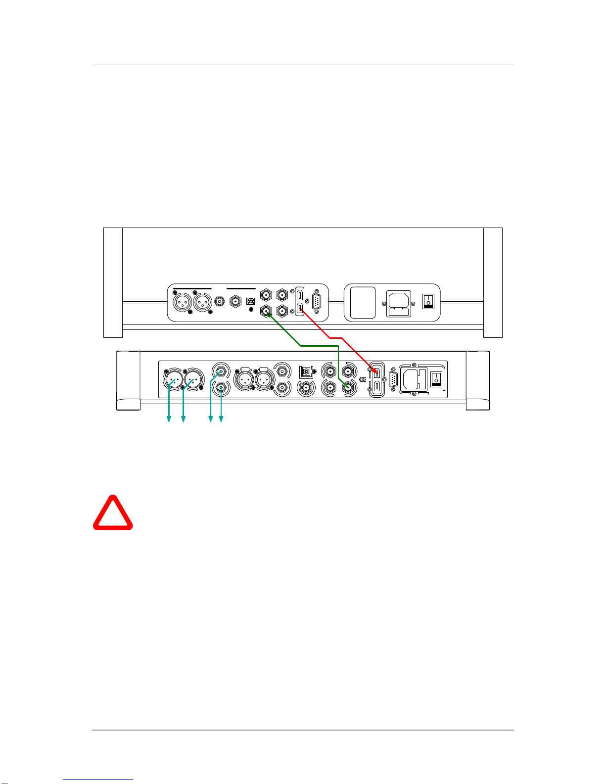
Connecting to a Dual AES Source
Check that your source equipment is capable of Dual AES operation.
•Connect the AES1 (or AES A) output on your source equipment to the AES1 input on the DAC rear
panel and the AES2 (or AES B) output to the AES2 input, using two XLR cables. Ensure the cables
are not swapped.
•Press the Input button repeatedly until both AES1 AND AES2 input indicators are lit.
The DAC will lock to the source, displaying in sequence (96k), Locking, 24/192 for example, if the
source is 24 bit data at 192kS/s.
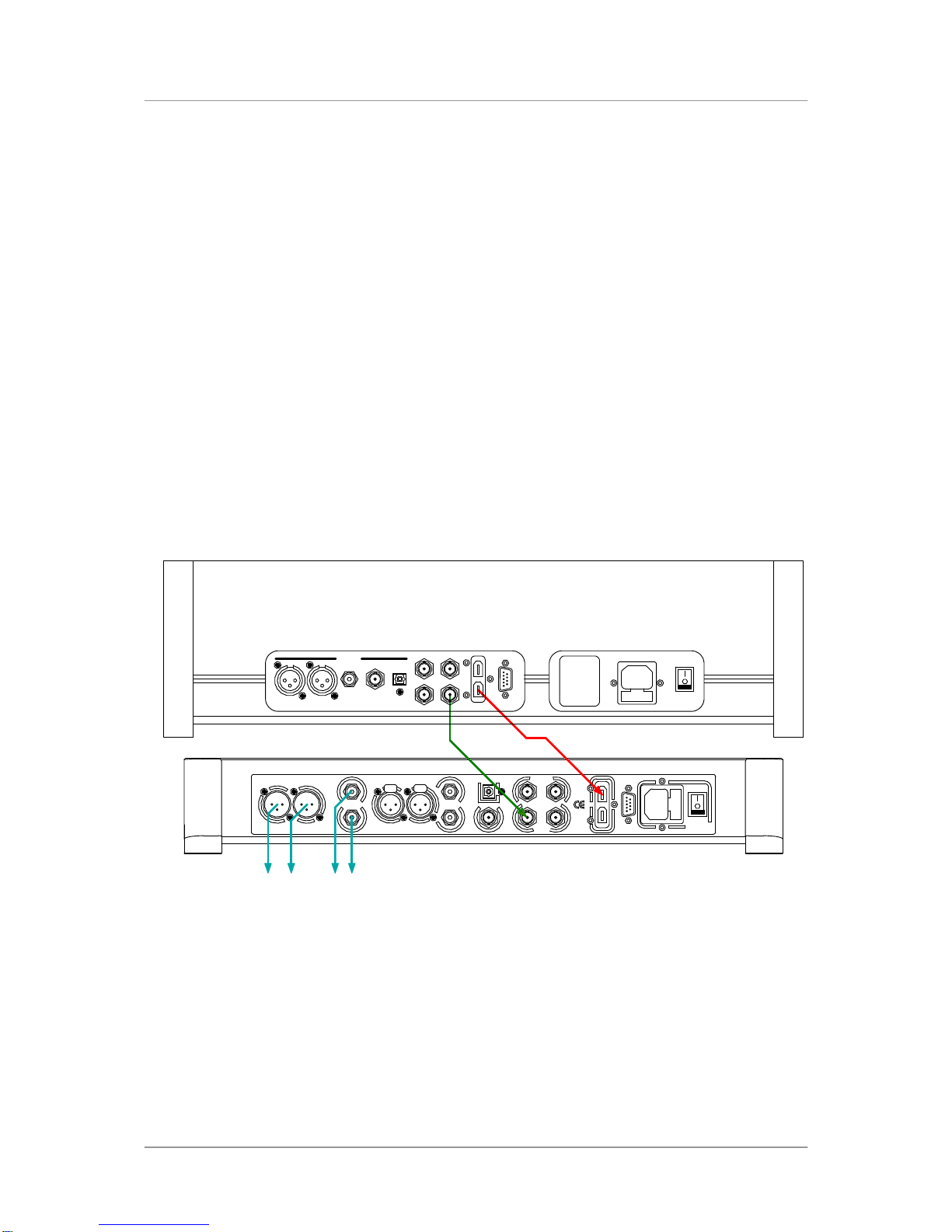
Connecting to an SDIF/DSD Source
Check that your source equipment is capable of SDIF PCM or DSD operation.
•Connect the CH1 output on your source equipment to the CH1 input on the DAC rear panel and the
CH2 output to the CH2 input, using two BNC cables. Connect the word clock output on your source
equipment to the WClk In connector on the DAC rear panel. Ensure the cables are not swapped.
•Press the Input button repeatedly until SDIF appears on the display.
PCM or DSD mode is automatically detected. The DAC will lock to the source, displaying in (44.1k),
Locking, 16/44.1 for example, if the source is a CD player. DSD is displayed if the source is DSD.
Proceed to Step 2.