Excellent HLPA07D543B User manual

Excellent
“The Name Defines The Quality”
Excellent Inverters
Operation Manual
We are your excellent choice
C -17, PAWANA INDUSTRIAL ESTATE, T 204, MIDC - BHOSARI, PUNE 411026
Tel: 7119505 / Fax: 020 - 7119405,
Automation & Control Systems
E-mail : acsindia@ vsnl.com
Visit us at : www.acs-india.com

CONTENTS
1.Introduction----------------------------------------------------------------------------------
1.1 Conformation upon delivery---------------------------------------------------------------------
1.2 Nameplate information----------------------------------------------------------------------------
2. Safety And Precautions ----------------------------------------------------------------
2.1 Before delivery the current----------------------------------------------------------------------
2.2 In delivery of current------------------------------------------------------------------------------
2.3 In running condition-------------------------------------------------------------------------------
3. Standard Specifications----------------------------------------------------------------
3.1 Individual specification----------------------------------------------------------------------------
3.2 Common specification----------------------------------------------------------------------------
4. Storage And Installation----------------------------------------------------------------
4.1 Storage-----------------------------------------------------------------------------------------------
4.2 In working condition-------------------------------------------------------------------------------
4.3 Positioning-------------------------------------------------------------------------------------------
5. Wiring----------------------------------------------------------------------------------------
5.1 Main circuit schematic diagram----------------------------------------------------------------
5.2 Terminals--------------------------------------------------------------------------------------------
5.3 Standard connection diagram------------------------------------------------------------------
5.4 Caution on wiring----------------------------------------------------------------------------------
6. Description Of Digital Operator------------------------------------------------------
6.1 Display status--------------------------------------------------------------------------------------
6.2 Explanation of programming the parameter------------------------------------------------
7. Trial Operator Procedure---------------------------------------------------------------
8. Function List-------------------------------------------------------------------------------
9. Detail Explanation Of Function------------------------------------------------------
10 .Maintenance, Inspection And Troubleshooting-------------------------------
10.1 Precaution about main an d inspection-----------------------------------------------------
10.2 Period main and inspection item-------------------------------------------------------------
10.3 Error inspection and its troubleshooting----------------------------------------------------
10.4 Troubleshooting-----------------------------------------------------------------------------------
11. Peripherals Devices And Specifications Of Option--------------------------
11.1 Peripheral devices-------------------------------------------------------------------------------
11.2 Proper specification of option-----------------------------------------------------------------
12. Appendices--------------------------------------------------------------------------------
12.1 Appendices demonstrations-------------------------------------------------------------------
12.2 Record and feedback from the user---------------------------------------------------------
1
1
2
2
2
3
3
3
3
4
5
5
5
5
6
6
7
9
10
11
12
13
14
15
20
53
53
53
54
56
57
57
58
59
59
70
Page no.

1. Introduction
Thank you for purchasing our high quality Excellent HLP series inverter.Before installation
and operation, please read the instruction in this manual throughly. For your safety, the
product should only be installed, tested and programmed by professional personnel. If
you have any questions or problem, please contact our local agency. The information
contained in this manual is subject to change without notice.
WARNING indicates precautions that, if not avoided, could result in death or serious
injury to personnel.
CAUTION indicates precautions that, if not avoided, could result in minor or
moderate injury to personnel and damage to equipment.
WARNING
1.Always turn off the input power supply before wiring.
2.Do not touch any inner part of the inverter when the Charging lamp is still on, shortly
after the AC power is cut off.
3.Do not check signals while the inverter is running.
4.Do not attempt to modify or alter the inverter by yourself, doing so can result in electrical
shock or injury or even explosion.
5. Be sure to ground the E terminals.
1.Do not perform voltage withstand tests on the inverter.
2.Never connect the AC main circuit power supply to output terminals U.V and W.
3.This drive contains ESD (Electrostatic Discharge) sensitive parts and assemblies Static
control precautions are required when installing, testing, or servicing this assembly.
Component damage may result if ESD control procedures are not followed.
4.Installation, testing and maintenance must be performed by professional person.
5.The inverter should be discarded as industrial waste. Avoid burning.
CAUTION
1.1 Receiving
Before unpacking please check the following:
1. Inspect the entire exterior of the inverter to see if , there are any scratches or other
damage resulting from shipping.
2. Check if there is an inverter and an operation manual in the packages as soon as you
open the package.
3. Check the model on the nameplate on the side of the inverter to see if this is the right
model you want.
4. Check if there is something is wrong on the inner parts, wiring and circuit board.
5. Use a screwdriver to other tools to check for tightness.
6. Check if there is any other things in the machine.
7. Check if the operator buttons are all right.
8. Check if the optional device you ordered is contained in it.
9. Check if there is a certificate of qualification and warranty card.
1

MODEL : HLPA07D543B
INPUT : 3PH415V50Hz
OUTPUT : 3PH415V17.5A7.5KW
FREQ-RANGE : 0.5-400Hz
EXCELLENT DRIVES
1.2 Nameplate information:
2. Safety precautions
2.1Before delivery of Current
CAUTION
1. This symbol is of ground terminal, make sure to ground it properly
2. Do not connect electromagnetic switches or contactors to the output circuit.
Marked edges RED
E(Circuit terminal)
WARNING
1. R.S.T terminals are power input terminals, never mix them with the U.V.W terminals
Be sure that the wiring of the main circuit is correct.
CAUTION
===
KM
X
X
1.Always hold the case when carrying the inverter. If the inverter is held by its cover, the
main body of the inverter may fall, possibly resulting in injury.
2.Mount the inverter to a metal or other noncombustible material.
3.Install the inverter in a safe site, avoid high temperature, direct sunlight, humidity air or water.
4.Keep the inverter from the reach of children.
5.Install a cooling fan or other cooling device when installing more than one inverter in the
same enclosure so that the temperature of the air entering the inverter is below 40 C
6. Check whether the front cover is attached before turning on the power supply. Do not
install the inverter in a space with explosive gas.
7. If the inverter is used at or above seal
level, the cooling efficiency will be worse,
so please run it downgraded.
8. Do not connect contactors and related
capacitor or
voltage dependent resistor
etc, to the output circuits
9. If it is must to connect such devices, be
sure to guarantee no voltage or current
supplied to output when operating these
devices. Otherwise, it will result in
damage to the inverter. The installation
diagram for this is forbidden.
2
Model:
0
400

WARNING
Never add or remove motor while it is running. Surge current, if created, will cause damage to
the inverter, even may cause burning of the main circuit.
2.3 In running condition
1.Never remove the front cover of the inverter while it is running.
2.Do not come close to the machine when the fault restart function is used. If the alarm is
cleared, the machine may start moving suddenly.
3.The function of the STOP button can only br available after setting. It is different from the
emergency stop button. Please note.
CAUTION
CAUTION
1.Do not touch the heat sink, braking resistor, or braking resistor unit. These can become very
hot.
2.Be sure that the motor and machine is within the applicable ranges before starting the
operation.
3.Do not check the power signals while the inverter is running.
4.Be careful when changing inverter settings. The inverter has been preset to factory setting.
5.Do consider the noise, vibration, and the speed limit of the motor and mechanical devices
when the inverter is running at or above the frequency of 50Hz.
3. Standard Specifications.
3.1 Individual Specifications.
MODEL Input voltage Power Driver
Capacity Output
Current Suitable
Motor
(KW) (KWA) (A) (KW)
HLPA00D423B
HLPA0D7523B
HLPA01D523B
HLPA02D223B
HLPA0D7543B
HLPA07D543B
HLPA005543B
220V 50Hz 0.4 1.0 2.5 0.4
220V 50Hz 0.75 2.0 5.0 0.75
220V 50Hz 1.5 2.8 7.0 1.5
220V 50Hz 2.2 4.0 10 2.2
3F400V 50Hz 0.75 2.2 2.7 0.75
HLPA01D543B 3F400V 50Hz 1.5 3.2 4.0 1.5
HLPA02D243B 3F400V 50Hz 2.2 4.0 5.0 2.2
HLPA03D743B 3F400V 50Hz 3.7 6.8 8.5 3.7
HLPA05D543B 3F400V 50Hz 5.5 10 12.5 5.5
3F400V 50Hz 7.5 14 17.5 7.5
HLPA001143B 3F400V 50Hz 11 19 24 11
HLPA001542B 3F400V 50Hz 15 26 33 15
HLPA18B543B 3F400V 50Hz 18.5 32 40 18.5
HLPA002243B 3F400V 50Hz 22 37 47 22
HLPA003043B 3F400V 50Hz 30 52 65 30
HLPA003743B 3F400V 50Hz 37 64 80 37
HLPA004543B 3F400V 50Hz 45 72 91 45
3F400V 50Hz 55 84 110 55
HLPA007543B 3F400V 50Hz 75 116 152 75
HLPA009043B 3F380V 50Hz 90 134 176 90
HLPA011043B 3F400V 50Hz 110 160 210 110
HLPA013243B 3F400V 50Hz 132 84 110 132
HLPA016043B 3F400V 50Hz 160 230 304 160
3

2.2 Common Specifications.
Control Method
Input Power Supply
Output frequency Range
Frequency Precision
Frequency Analog input
control
resolution Digital input
Output Resolution
Operating setting
Method
Analog setting
Method
Other function
Acceleration/Decel
time
Voltage/frequency
characteristics
Torque Control
Multi-function input
terminals
Multi-funciton output
terminals
Other functions
Digital Operator
monitor
Communication
Control
Ambient Temp
Ambient Humidity
Vibration
Instantaneous over
current
Over Load
Motor Overload
protection
PWM
415V Power Supply: 415+15%
220V Power Supply: 220+15%
0.10~400.00Hz
Within 0.1% of max. output frequency(25 C (53 F)+
10 C(+21.2 F)) during analog input & within 0.01% of the
set output frequency( )
during digital input
1% of Max operating frequency
0.01Hz
0.01 Hz
Press or 10 set
0-5V/0-10V, 4-20mA/0-20mA
frequency upper/lower limit, starting frequency stopping
frequency, three skip frequencies can be individually set.
Counter setting etc.
Four selectable combinations of independent acceleration
and deceleration setting Range: 0.1sec to 6500sec.
Set V/F curve at will.
Max Torque upto 10.0% max output voltage .The starting
torque can reach 150% of max output voltage at 1.0Hz.
6 multi-function input terminals for 8 multi-speed, counter
4 Accel/Decel time select, UP/DOWN command, external
emergency stop.
5 multifunction output terminals for the displaying and
warning of no- running, zero speed, counting and external
fault information.
Decelerating stop or self-stop, DC brake, auto restart
tracking, easy PLC auto energy-saving adjustable carrier
Frequency(Max 20KHz) etc.
Frequency command, output frequency, speed output
current, output voltage. DC bus voltage and of rotation.
Rs485
-10 C(-21.2 F) to 40 C(+84.8 F)
0-95% RH(relative humidity).
0.5G (0.5 x 9.8 = 4.9 m/s) or lower.
Approx. 200% rate current.
Inverter: 150% 1 minute
electronic thermal overload relay..
4

Storage & Installation
Storage
This product must be stored in its package box before installation. Pay special
attention to the followings when in shortages
1. It must be stored in a dry place without rubbish or dust
2. The suitable temperature for storage is between-20 C and + 65 C
3. The relative humidity required is 0-95%, no condensation.
4. There is no corrosive gas or liquid.
5. It’s better to lay the inverter in its original package on a shelf.
5
Location
Note: The working conditions of the inverter will affect its services life, please
install the inverter under the following conditions.
1. Ambient operating temperature -10 C to 40 C.
2. IP rating: IP 20 for all models
3. Protected from rain & moisture.
4. Shielded from direct sunshine.
5. Free from metallic particles and corrosive gas.
6. Free from excessive vibration.
4.3 Positioning
1. There must be enough space left around the inverter for easy maintenance and
effective ventilation .See diagram 1
2. The inverter must be installed with heat sink ribs oriented vertically for effective
ventilation.
3. If there is any instability when installing the inverter, please put a flat board under
the inverter bottom base and install again .If the inverter is installed on a loose
surface, stress may cause damage in main circuit.
4. The inverter should be installed on non-combustible materials, such as iron plates
5. If several inverter are installed together in one cabinet, please add heat
dissipation plates and provide enough space between the inverters.
Caution
War ni ng
********
*********
50
50

5 Wiring
5.1 Main circuit schematic diagram
6
Excellent
Caution
Warning
************
********
1. Power supply: Verify that the inverter rated
voltage coincides with AC power supply voltage.
2. Fuse breaker or ground fault interrupter.
3.Magnetic contactor
Note: Don’t use the magnetic contactor as the
power supply on/off to the inverter.
4.AC reactor for power factor improvement
5.Excellent - inverter
6. 3 phase squirrel cage induction motor.

E R S T U V W P Pr
E R S T U V W P1P Pr
R S T E P N U V W
HLPA00D423B-HLPA02D223B
HLPA0D7543B-HLPA03D743B
HLPA05D543B-HLPA07D543B
HLPA001143B-HLPA030043B
7
FA FB FC EV SPL SMP SPH RST DCM REV FOR
KA KB UPF DRV +10 VI AI ACM AM RS- RS+
Control circuit terminals arrangement
FA FB FC KA KB IPV UPF DRV DCM SPL SPM SPH RST REV FOR +10 VI AI ACM AM RS- RS+
HLPA00D423B HLPA01D523B HLPA0D7543B HLPA02D243B
HLPA02D22B HLPA03D743B HLPA07543B
UPF DRV FOR REV DCM RST SPH SPM SPL P24 AM ACM AI VI +10 EKB EKA EFC EFB EFA
HLPA02D22B HLPA03D743B HLPA07543B
5.2 Terminals
5.2.1 Main circuit Terminals Arrangement

Functional description of main circuit terminals
SYMBOL FUNCTION DESCRIPTION
R.S.T input terminal of AC line power
P.Pr External braking resistor terminals
P .P1 External DC reactor terminals
P.N External Braking unit terminals
U.V.W. Output terminals to motor
E Ground terminal.
Functional description of control circuit terminals
Symbol Functions Factory setting
FOR Multi -Function input 1 Forward run
REV Multi -Function input 2 Reverse run
RST Multi -Function input 3 Reset
SPH Multi-Function input 4 High Speed
SPM Multi-Function input 5 Medium Speed
SPL Multi -Function input 6 Low Speed
DCM Ground common for input
terminals
EV(IPV) + 12V power supply Max output current 200mA
P24 +24V power supply Max output current 200mA
+10 Power supply for analog frequency +10V
VI Analog frequency reference 0 ~+10Vcorresponding to
input(voltage) highest operating frequency
AI Analog frequency reference input 4~20m
(current)
ACM Common for analog input signal
DRV Multi -function output terminal 1 Optical couple output DC
24V/100mA
UPF Multi-funcation output terminal 2
FA(EFA), Fault relay output(N/O or
FB(EFB), Multi-funcation output terminal 3 N/C) 3 A/250VAC,3A/30VDC
FC(EFC)
KA(EKA) Multi-funcation output terminal 4 Fault relay output(N/O)
KB(KEB) 3A/250AC,3A/30VDC
AM Digital frequency output terminal 0-10V
RS+RS- RS-485 communications
8

9
5.3 Standard Connection Diagram
The whole circuit is divided into two parts. Main power circuit terminal connections and control
circuit terminal connections. Users can see the main circuit terminal, and the control
circuit terminals after removing the outer cover .The terminals must be connected as
shown in the following diagrams .
The following diagram shows the standard connection of Excellent drive.
M
U
V
W
PrP1
R
S
T
E
VR(+10V)
VI
ACM
AI
FOR
REV
RST
SPH
SPM
SPL
DCM ACM
AM Analog frequency output
0~10V
DRV
UPF
DCM
Multi-function Output <Relay O/P>
24V/100mA
RS+ RS-
KA
KB
EV(IPV)
AC Power Supply
10K
Analog Current
input
Multi-function output <relay N/O>
3A/250VAC 3A/30 VDC
+ 12V
FC
FA
FB
Multi-function output <relay N/O N/C>
3A/250VAC
3A/30VAC
P
DC Reactor Braking Resistor
M
U
V
W
PrP
R
S
T
E
VR(+10V)
VI
ACM
AI
FOR
REV
RST
SPH
SPM
SPL
DCM ACM
AM Analog frequency
0~10V
DRV
UPF
DCM
Multi-function Output
24V/100mA
RS+ RS-
KA
KB
EV(IPV)
AC Power Supply
10K
Analog Current
input
Multi-function output <relay N/0>
3A/250VAC 3A/30 VDC
+ 12V
FC
FA
FB
Multi-function output <relay N/0 N/C>
3A/250VAC
3A/30VAC
Braking Resistor

5.4 Cautions on Wiring
5.4.1 For main circuit wiring
1) No Fuse Breaker required for the power supply and the input terminals (R.S.T).
(If using ground fault interrupter, please choose the one corresponding to high frequency)
2) Never connect AC power to the output terminals of U.V.W. On the inverter.
3) Output wire must not be in touch the metal part of the outer cover ,or it will cause earth short-circuit.
4) Phase -shifting capacitor, LC, RC noise filters, etc. can never be connected between motor and
output terminals(U.V.W)
5) The main circuit wire must be enough far away from other control equipments.
6) If there is a relatively long distance between the inverter and the motor, please lower the carrier
frequency. Because the high leakage current will cause damage to the inverter and other
equipments.
7) If the wire is more than 15m for 220V class products (or 30m for380Vclass products)between
the inverter and the motor, please choose an AC motor ,special for inverter or add a reactor
on the side of the inverter, because a very high dv/dt produced in the motor coil will cause
damage to the insulation layer of the motor .
Model
CB
Wire size
Screw
Model
CB
Wire size
Screw
HLPA00 HLPA0 HLPA01 HLPA0 HLPA0 HLPA01 HLPA02 HLPA03 HLPA05
D423B D7523B D523B2 D223B D7543B D543B D243B D743B D543B
16A 16A 32A 32A 16A 16A 16A 16A 32A
2.5mm 2.5mm 2.5mm 4mm 2.5mm 2.5mm 2.5mm 2.5mm 4mm
M4 M4 M4 M4 M4 M4 M4 M4 M5
HLPA07 HLPA00 HLPA00 HLPA18 HLPA00 HLPA00 HLPA00 HLPA00 HLPA0055
D543B 1143B 1543B D543B 2243B 3043B 3743B 4543B 43B
40A 63A 63A 100A 100A 160A 160A 200A 200A
6mm 6mm 10mm 10mm 16mm 25mm 25mm 25mm 35mm
M5 M6 M6 M6 M8 M8 M8 M10 M10
2 2 2 2 2 2 2 2 2
2 2 2 2 2 2 2 2 2
10
M
U
V
W
NP
R
S
T
E
+10V
VI
ACM
AI
FOR
REV
RST
SPH
SPM
SPL
DCM ACM
AM Analog frequency
0~10V
DRV
UPF
DCM
Multi-function Output <O/P>
24V/100mA
EKA
FKB
P24
AC Power Supply
10K
Analog Current
input
Multi-function output <relay N/O>
3A/250VAC 3A/30 VDC
(+ 12V)
EFC
EFA
EFB
Multi-function output <relay N/O, N/C>
3A/250VAC 3A/30VAC
RS485
DC Braking resistor unit
Note:- The parameter above are only for reference, not a standard.
Specification of wire
5.4.2 For control circuit wiring ( signal line)
1. Separate control circuit wire from main circuit wire and other high -power lines .
2. Use twisted -pair or shielded twisted -pair cables for control circuits to prevent
operating faults .The size should be 0.5-2mm.
3. Use the control terminals correctly according to your needs.
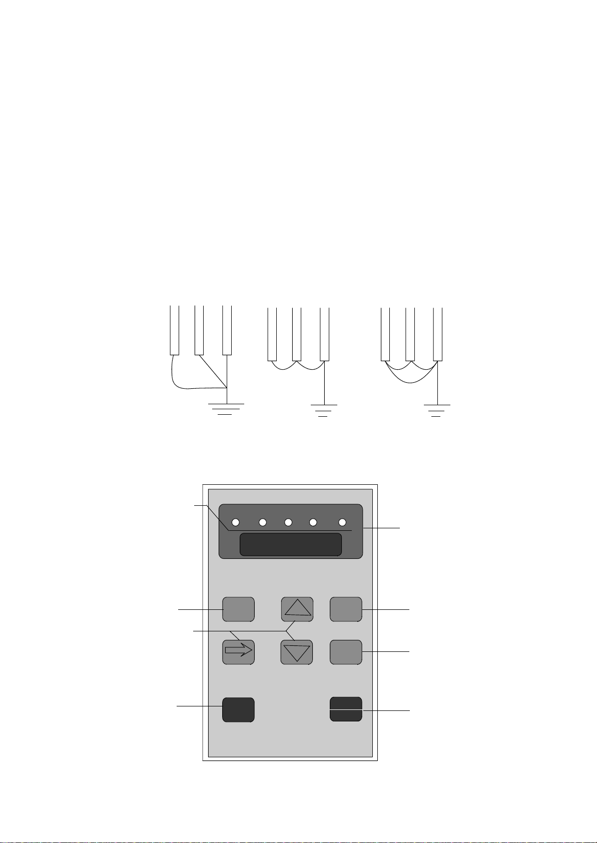
5.4.3 Grounding
1. Choose grounding wires according to the requirement of the electrical equipments .
2. Avoid sharing grounding wires with other large power equipment .The grounding wire
should be kept away from the power supply wires .
3. The grounding method for several inverter together should be done as the first and second
diagrams. Avoid the third diagram .
4. Short grounding wire are better.
2
(1) Correct (2) Correct (3) Wrong
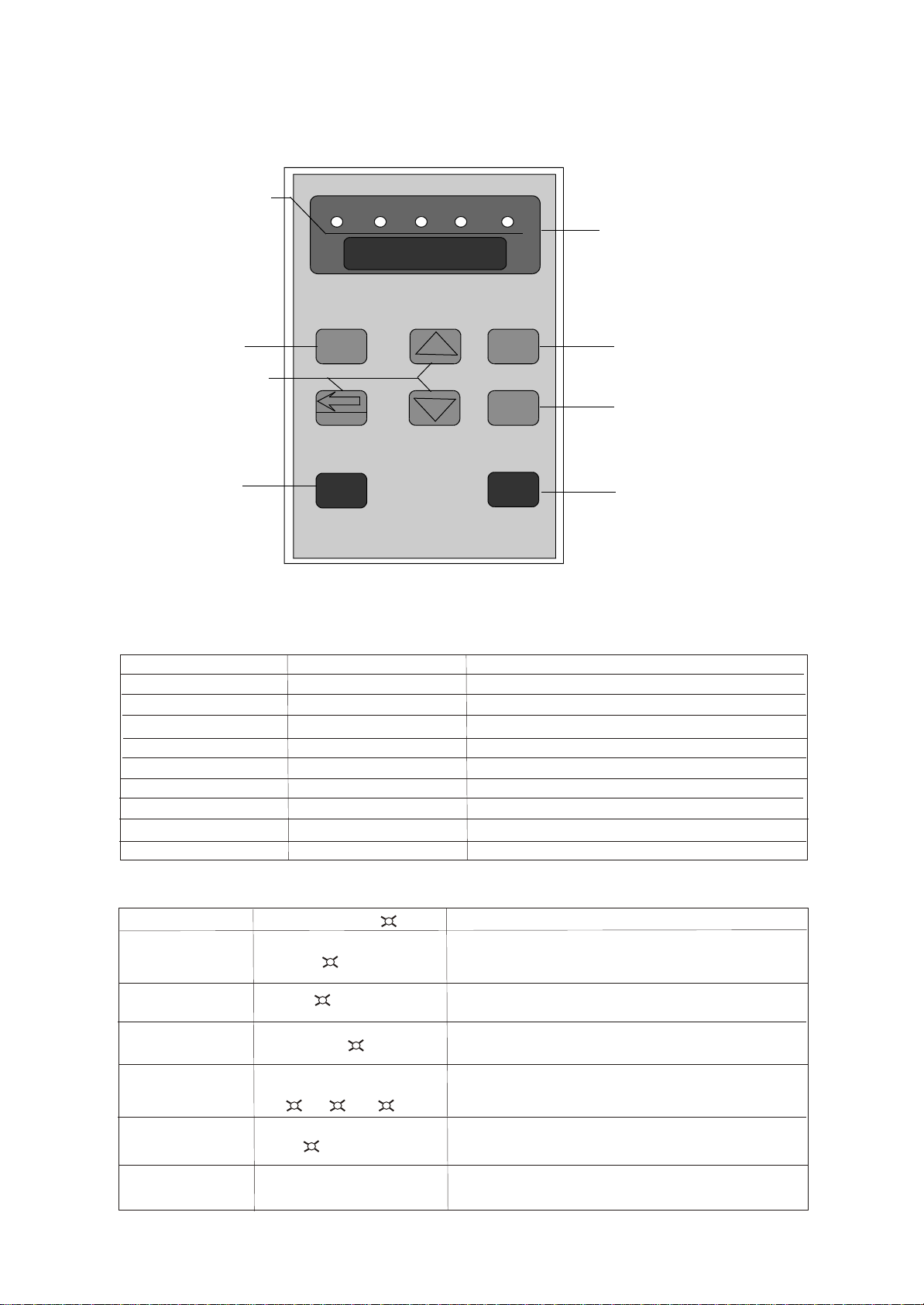
6.Description of Digital Operator
11
2
8.8.8.8.8.
FOR REV HZ AR/min
F/R PROG
ENTER
STOP
RESET
RUN
Run Key Stop/RESET Key
Read/Write Key
Function Selection
key
Main Display Area of
Voltage, frequency, current AC
DC voltage, rotation speed
counter, temperature.
Operation ModeIndicators forword
run,reverserun frequency current
speed
Forward or reverse
run key
Numerical key
(use for incrementing &
decrementing thesettings)
Output
6.2 Display Status
6.2.1Display status description
Indicators Status Explanation
FOR On Forward run
REV On Reverse run
HZ On Display set frequency or output frequency
A On Display output current
ROTT On Display motor speed
HZ A On Display DC Voltage
A ROTT On Display output voltage
HZ ROTT On Display counting data
HZ A ROTT On Display inverter temperature
6.2.2 Explanation of data display
Display item Indicator On Explanation
050.00 HZ Present set frequency or output frequency.
5.5 A Current (in amperes)
1440 ROTT Motor speed (in rpm)
30.0 HZ A ROTT Present inverter heat sink temperature
CD 100 HZ Function item
EOC.A Error information
12
8.8.8.8.8.
FOR REV HZ AR/min
F/R PROG
DISP SET
STOP
RUN
Run Key Stop/RESET Key
Read/Write Key
Function Selection
key
Main Display Area of
Voltage, frequency, AC current
DC voltage, rotation speed
counter, temperature
Operation Mode Indicators
forword run, reverse run
frequency current speed
Forward or reverse
run key
Numerical change key
Output

6.3Explanation of programming the parameters.
Example
Procedures Data Display Explanation
power on dsp.1flashing FOR Hz Self inspection after power on, showing
uEr1.3 its version number ( flashing ), then
000.00 its set frequency
Prog CD 000 FOR Hz Function number CD000.
Enter 000.0 FOR Hz Display the value of FUNCTION CD000
Enter 50.00 FOR Hz Modify the value of Function CD 000.
END 50.00 Display :End 50.00 CD0001
CD001 withdraw form the programming status
prog FOR Hz
050.00
Run 50.00 FOR H z Display : Forward run status and set
frequency
50.00 FOR Hz Switching to display running frequency.
0.00 50.00
Disp
0005.0 FOR Hz Switching to display output current.
Disp
01440 FOR Hz Switching to display rotating speed.
Disp
050.00 FOR Hz Return to main display ,showing set
Prog frequency.
050.00 REV Hz Forward RUN/REVERSE RUN shift
F/R display '' reverse run '' status.
050.00 REV Hz Switching to frequency adjustable status.
030.00 REV Hz Adjust the set frequency, that is the value
of CD000.
030.00 REV Hz Enter the new value which will be
ENTER remembered as CD000.
Stop 030.00 REV Hz Stop .
13

Function List Parameter and Function List (Part 1)
Item Function Function Set range & function Factory
code explanation Setting
Cd000 Main Frequency 0.00~400.00 Hz 0.00
CD001 Max output voltage 0-1V---* 220/380
CD002 Base Frequency 0.01~400.00Hz 50.00
CD003 Voltage at medium
Frequency 0.1V---* 15/27.5
CD004 Medium Frequency 0.01~400.00Hz 2.50
CD005 Voltage at lowest
Frequency 0.1~50.0V 8.0/13.5
CD006 Lowest frequency 0.01~20.0Hz 0.50
CD007 Max operating system 50.00~400.00Hz 50.00
CD008 Frequency upper limit 0.01~400.00Hz 50.00
CD009 Frequency lower limit 0.00~400.0Hz 0.00
CD010 Parameter lock select 0: invalid 1: valid 0
CD011 Factory setting 00~10 only No.08 meansto 00
to reset to factory setting
CD012 Accel.Time 1 0.1~6500.0S 10.0/25.0
CD013 Decel.Time 1 0.1~6500.0S 10.0/25.0
CD014 Accel.Time 2 0.1~6500.0S 50.0
CD015 Decel.Time 2 0.1~6500.0S 50.0
CD016 Accel.Time 3 0.1~6500.0S 100
CD017 Decel.Time 3 0.1~6500.0S 100
CD018 Accel.Time 4 0.1~6500.0S 200
CD019 Decel.Time 4 0.1~6500.0S 200
CD020
Reserved
CD030
CD031 Start mode 0: start from starting frequency 0
1: start by former frequency
track
CD032 Stop mode 0: decelerate to stop 1:free 0
run to stop
CD033 Control mode select 0: digital operator
1: external terminals 0
2: communications
CD034 Frequency command 0: digital operator
1: external terminals 0
2: communications
CD035 Carrier frequency 0~15 5
CD036 Jog frequency 0.00~4.00.0Hz 5.00
CD037 FOR/REV select 0: Reverse run forbidden 1
1: Reverse run available
CD038 “STOP” key select 0: Stop key ineffective in
remote control mode
1: Stop key effective in
remote control mode
CD039
Reserved
CD040
CD041 Starting frequency 0.1~10.0 Hz 0.5
14
Applied parameter
Basic parameter

Function List Parameter and Function List (Part 1)
Item Function Function Set range & function Factory
code explanation Setting
CD042 Stopping Frequency 0.1~10.0 Hz 0.5
CD043 Torque Boost 0-10% 2.0%
CD044 Skip Frequency 1 0.00~400.00Hz 0.00
CD045 Skip Frequency 2 0.00~400.00 Hz 0.00
CD046 Skip Frequency 3 0.00~400.00Hz 0.00
CD047 Skip Frequency 0.00~2.00 Hz 0.5
CD048 Reserved
CD049
CD050 Multi -input 1 ( FOR) 00: invalid 01:run 02: forward 02
CD051 Multi- input 2 ( RST) run03:reverse run 04:stop 03
CD052 Multi-input 3 (RST) 05:for/rev run 06: jog 10
CD053 Multi-input 4 ( SPL) 07:forward jog 08:reverse jog 17
CD054 Multi-input 5 (SPL) 09:external emergency stop 18
Cd055 Multi-input 6 (SPL) 10:reset 11: reserved 19
12: overheat of motor 17: high
speed 18: medium speed
19:low sped 20:multi -speed1
21:multi -speed2
22:multi-speed3
23:accel/decel select 1
24:accel/decel select 2
CD056 Multi-output1( DRV) 00: Invalid 01:run mode 01
CD057 Multi-output2 ( UPF) 02: Fault signal 03: zero speed 05
CD058 Multi-output3 FA FB 04: Brake indication 05:Up to 02
FC) setting frequency 06: Up to
desired frequency 1 07:Up to
CD059 Multi -output 4 desired frequency 2 08 :in 00
( KA KB) accelerating 09:In
decelerating 10: Inverter
overload 11:Motor overload
13: Under voltage 14: Finish
indication for single stage
15: Finish indication for
process 16: counting arrival
27: Drafting arrival 28: PID
lower limit alarm 29; PID
upper limit alarm 30: Fan
running 31:Reserver
32:Braking resistor action
CD060 Multi -output 5( AM) 1
CD061 UP -to desired 0.00~400.00 Hz
frequency 1 setting
CD062 UP-to desired 0.00~400.00 Hz 0.00
frequency 2 setting
Cd063 UP -to frequency 10.10~10.00 Hz 0.50
setting detection width
CD064 Counter set 00~65500 00
15

Function List Parameter and Function List
Item Function Function Set range & function Factory
code explanation Setting
CD065 Analog input select 0:~10V 1:0~5V
2:0~20mA 3:4~20mA 0
4:0~10V plus 4~ 20mA
CD066 Lower analog frequency 0.00~400.00Hz 0
set point
CD067 lower analog frequency 0:Positive
bias direction 1: negative
CD068 Higher analog frequency 0.00~400.00Hz 50.00
set point
CD069 Higher analog frequency 0: positive
bias direction 1: negative 0
CD070 Negative bias reverse 0:invalid 1:vaild 1
select
CD071 Analog output gain 0.0~100.0% 100
CD072 Up/down function select 0:recoreded 1
1: non-recoreded
CD073 Reserved
Cd075
0: normal running 0
1: external control four speed
Cd076 PLC mode select 2: external control multi
speed3:ddistrubance 4:inner
control multi speed
0: stop after one circle 0
1:cirulating running 2: stop after
auto running one circle (with
CD077 Auto PLC select STOP interval ) 3: auto
circulating running
(with STOP interval)
CD078 PLC running direction 0~255(0:Positive 1: Negative )
CD079 PLC accel/decel .time 0~65535
CD080 Multi-speed 2 0.00~400.00 Hz 15.00
CD081 Multi-speed 3 0.00~400.00 Hz 20.00
CD082 Multi-speed 4 0.00~400.00 Hz 25.00
CD083 Multi-speed 5 0.00~400.00 HZ 30.00
CD084 Multi-speed 6 0.00~400.00 Hz 35.00
CD085 Multi-speed 7 0.00~400.00 Hz 40.00
CD086 Multi-speed 8 0.00~400.00 Hz 0.50
CD087 Timer 1 0.0~6500.0s 10.0
CD088 Timer 2 0.0~6500.0s 10.0
CD089 Timer 3 0.0~6500.0s 0.0
CD090 Timer 4 0.0~6500.0s 0.0
CD091 Timer 5 0.0~6500.0s 0.0
CD092 Timer 6 0.0~6500.0s 0.0
CD093 Timer 7 0.0~6500.0s 0.0
CD094 Timer 8 0.0~6500.0s 0.0
CD095 Reserved
CD0119
16
I/P & O/P terminals

Function List Parameter and Function List (Part 1)
Item Function Function Set range & function Factory
code explanation Setting
CD120 Stall prevention select 0:invalid 1: valid 1
CD121 Stall prevention level 0~200% 150
during accel
CD122 Stall prevention level 0~200% 0
during running
CD123 Stall prevention level
during decel 0~200% 150
CD124 Reserved
CD125 Overtorque detection 0~200% 1.0
level
CD126 Overtorque detection 0~200%
time
CD127 Reserved
CD129
CD130 Rated voltage according to the motor nameplate *
CD131 Rated current according to the motor *
nameplate 40
CD132 Motor poles 02-10 1440
CD133 Rated rotatory speed 00---9999
CD134 Reserved
CD139
CD140 DC braking level 0.0~20.0% 2.0
CD141 DC braking time at 0.0~25.0S 0.0
starting
CD142 DC braking time at 0.0~25.0S 0.0
stopping
CD143 Speed search time 0~20.0S 5.0
CD144 Speed search current 0~200% 150
level
CD145 Power loss allowable 0: invalid 1:restart by speed 0
search
CD146 Number of auto restart 0.1~ 5.0s 0.5
CD147 Attempt 0---10 00
CD148 Auto voltage regulation 0: invalid 1:valid 1
CD149 Auto energy saving 0~10% 0
CD150 P 0.0---1000.00% 100%
CD151 I 0.1~3600.00s 5.0
CD152 D 0.01~10.00s
CD153 Target value 0.0~100.0%
CD154 Target value source 0: digital operator 1: external *
terminals(0-10V) *
CD155 PID upper limit 0~100% 100%
CD156 PID lower limit 0~100% 0%
CD157
Reserved
CD159
17
Applied parameter
Basic parameter

Function List Parameter and Function List (Part 1)
Item Function code Function Set range & function Factory Setting
explanation
CD168 Display mode select Rated 0-15 00
CD169 Voltage of the inverter According to the actual *
model set *
CD170 Rated current of the inverter according to the actual *
CD171 Software version model ---
CD172 Fault Record 1 Note :- means no fault ---
CD173 Fault Record 2 record ---
CD174 Fault Record 3
CD175 Fault Record 4
CD176 Fault cleared 00--10 (01 is fault record ---
cleared
CD177 Reserved
CD178 Frequency standard of the 0:50Hz 1:60Hz 0
inverter
CD179 Manufacture Date Factory set *
CD180 Sequence Number *
CD181 Reserved
CD250
18
Table of contents


