Sunfar C300 Series User manual

SHENZHEN SUNFAR ELECTRIC TECHNOLOGIES CO.,LTD
C300 series of Inverte
r
Non-sensor current vector-control
Manual

PREFACE
C300 series of non-sensor current vector-control inverter manual
PREFACE
Thank you very much for choosing C300 series of sensorless vector low-power
inverter.
This manual provides guidance of using the inverter safely and carefully, containing
introduction of installation, wiring, parameters list, routine maintenance, operating
rules and cautions, etc.
In order to make good use of the inverter properly and safely, please read this
manual thoroughly before using. It may lead to abnormal operation and failure,
reduce using life, even damage the equipment and cause personal injury if you use
it wrongly.
This manual is attachment together with the inverter. Please keep it well and it
would be available to engineering and installation personnel, repairing and
maintaining during the product functioning period. SUNFAR has the right to modify
and ameliorate products, data and dimensions without notice, so this manual is
updated and all the contents in this manual are subject to change without any
notice.
Notice of Using:
C300 is Sensorless vector low-power inverter. Under the operation mode of vector
controlling, the inverter carry out the semi-closed-loop control of electricity, while if
you use the motor that its capacity is lower than the inverter itself, please input the
motor Nameplate parameter [F1.15]~[F1.18] again.
SHENZHEN SUNFAR ELECTRIC TECHNOLOGIES CO., Ltd.

Table of Contents 1
C300 series of non-sensor current vector-control inverter manual
Table of Contents
1 INTRODUCTION …………………………………………………………………1
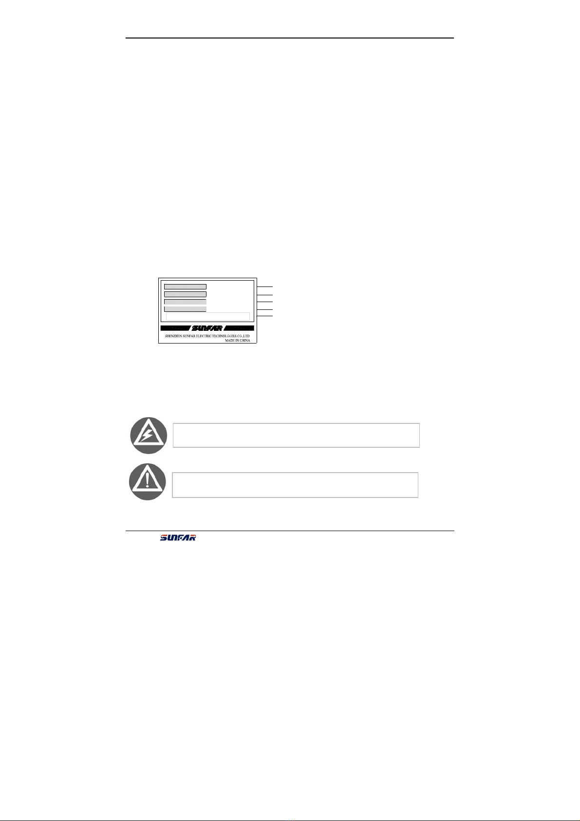
1.1 Model explanation …………………………………………………………..
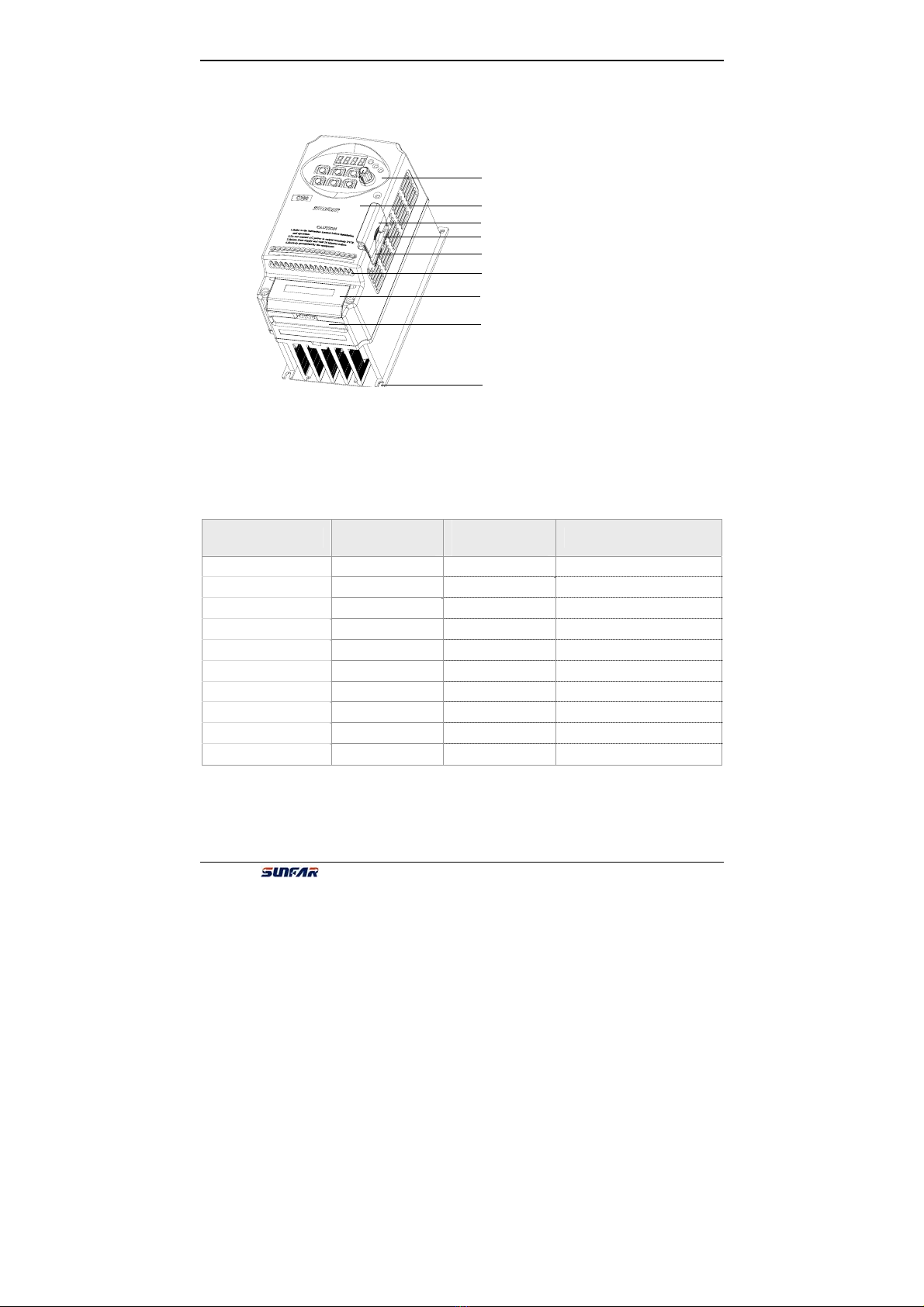
1.2 Appearance description ……………………………………………………
1.3 Model of inverter………………………………………………………………
1.4 Specifications………………………………………………………………..
2 INSTALLATION GUIDELINES……………………………………………….
2.1 Environmental requirements ……………………………………………… 5
2.2 Installation dimension of inverter ………………………………………………
3 WIRING PROCEDURE……………………………………………………7
3.1 Precautions …………………………………………………………………7
3.2 Wiring of external components ………………………………………………
3.3 Basic wiring ……………………………………………………………………
3.4 Terminal of main circuit ……………………………………………………
3.5 Terminal of Control circuit …………………………………………………
3.6 Wiring of RS485 interface and
remote panel interface………………………………………………………….
4 PANEL OPERATIONS……………………………………………………………
4.1Panel functions………………………………………………………………
4.2 Panel operation ………………………………………………………………
4.3 State monitor parameter ……………………………………………………….
4.4 Operations …………………………………………………………………….
5 PARAMETERS LIST………………………………………………………………
6 DESCRIPTION OF SPECIFIC FUNCTIONS …………………………………
6.1 Basic operation parameter unit ………………………………………………
6.2 Primary application of parameter unit……………………………………….
6.3 Analog I/O parameter unit …………………………………………………
6.4 Digital O/I parameter unit ……………………………………………….…
6.5 Auxiliary running parameter unit …………………………………………..
6.6 Multi-speed running parameter unit ……………………………………….
6.7 Advanced running parameter unit ………………………………………
1
1
2
3
3
6
6
7
8
8
9
10
11
12
13
14
14
15
16
17
19
39
39
45
51
54
58
64
67

2 TableofContents
C300 series of non-sensor current vector-control inverter manual
6.8 Wobble freq. running parameter unit ………………………………………74
6.9 PID control parameter unit …………………………………………………
6.10 Communication function parameter units ………………………………
6.11 Special function parameter unit …………………………………………
7 FAULT DIAGNOSIS AND COUNTERMEASURES………………………
7.1 Protective functions and countermeasures……………………………
7.2 Fault record inquiry ………………………………………………………
7.3 Reset ………………………………………………………………………
8 MAINTENANCE……………………………………………………………
8.1 Daily Maintenance ………………………………………………………
8.2 Damageable parts maintenance …………………………………………
8.3 Storage………………………………………………………………………
8.4 After sale services …………………………………………………………
9 USAGE EXAMPLE ……………………………………………………………
9.1 Panel on-off control, Panel potentiometer
setting frequency and V/F control methods…………………………
9.2 External control mode, external voltage
setting frequency and V/F control………………………………………
9.3 Multi-speed running, external control mode
and V/F control ……………………………………………………………
9.4 Panel on-off control,Panel potentiometer setting
frequency and linkage control with inverters ……………………………
9.5 PLC controls the startup and stop of inverter
and 3-speed operation………………………………………………….
Appendix RS485 COMMUNICATION PROTOCOLⅠ…………………
Appendix OPTIONⅡS…………………………………………………………
1. Operation panel …………………………………………………………
2. Brake resistance …………………………………………………………
78
82
83
86
86
89
89
94
94
95
95
96
97
97
97
99
99
101
113
113
114
78
82
83
86
86
89
89
94
94
95
95
96
97
97
97
99
99
101
113
113
114
70
72
76
77
80
80
82
83
84
84
85
85
86
87
87
88
89
90
91
94
106
106
107

PRECAUTIONS 1
C300 series of non-sensor current vector-control inverter manual
PRECAUTIONS
In order to use the inverter properly and safely, please read this manual carefully
before using. And you should follow the requirements of this manual to move, install,
run, operate and repair the inverter.
1. Opening
Please check any daⅠmage that may have occurred during transportation.
Please check whether the nameplate data of inverter is in accordance withⅡyour order, if anything wrong, please contact supplier immediately.
Our product is manufactured, packed and transported in the strict quality system. But
in case there is any error, please contact with our company or local agent, we will
solve the problem as quickly as possible.
zInverter’s nameplate data
2. Safety regulations
There are four kinds of symbols being related with cautions as follows:
Fig-1 Nameplate
Danger: If user does not operate according to requirements, it will lead
to death, grievous bodily harm or severe property loss.
Warning: If user does not operate according to requirements, it will
lead to injury or damage of inverter.
C300-4T0015
3PH 380V 50/60Hz
2.4KVA 3.7A
SOURCE:
OUTPUT:
SERIAL No.: 0123456789
TYPE:
Rated Parameters
Rated output capacity and current
Product series No.
Bar code
Inverter's model

2 PRECAUTIONS
C300 series of non-sensor current vector-control inverter manual
2.1 Installing
2.1.1. Do not put the inverter on the combustible material.
2.1.2. C300 series inverter can’t install in the explosive ambient.
2.1.3. Do not drop other material into the inverter.
2.2 Wiring
2.2.1. It must be operated by professional worker when wiring.
2.2.2. Please be sure to turn off the power supply at least 10 min before wiring.
2.2.3. Inverter and motor must be grounded correctly.
2.2.4. Be sure to wire or inspect the inverter after power-off at least10 minutes.
2.2.5. Electron components are sensitive about static electricity, so do not drop
other material in inverter or touch the main circuit.
2.3 Maintenance
It is forbidden to connect an AC power supply with the U, V and W output
terminals directly
1. Do not touch the radiator after power-off at least 10 minutes.
2. The earth terminal of inverter must be connected to ground reliably.
It is forbidden to disassemble and refit the inverter.
This symbol will hint some useful information.
This symbol will hint some items that need to be noticed in operation.

PRECAUTIONS 3
C300 series of non-sensor current vector-control inverter manual
3. Attention Notes:
3.1. Be sure to install the inverter in a well-ventilated ambient.
3.2. The temperature at variable-frequency will be higher than at line-frequency,
which is normal phenomenon.
3.3. The ordinary motor cannot run in the low speed for a long time, so user
should select the special motor for inverter or reduce the motor load under
the low speed.
3.4. When the altitude is over 1000m, the inverter will be valid to decrease the
rated current, and the rated current will decrease 10% when the attitude is
increased 1500m.
4 Dispose:
When you dispose inverter and its parts, please pay attention to:
Capacitor: The capacitors in inverter may explode when they are burned.
Plastic: Poisonous gas may be generated when the front panel is burned, please
pay attention to the waste gas when the plastic parts are burned.
Method: Please dispose inverter as industry rubbish.
Be sure not to connect the output terminals of inverter with the filter capacitors
and other surge absorbers.

SUNFAR C300 1
C300 series of non-sensor current vector-control inverter manual
1. INTRODUCTION
1.1 Model Explanation
1.2 Appearance description
1.2.1 Appearance of model I
It is fit for:C300-2S0002~C300-2S0007/C300-4T0004~C300-4T0007
Mounting hole
Cable inlet of main circuit
Cable inlet of control circuit
Remote panel interface
RS485 interface
Upper cover
Operation panel
``
C300 - 4 T 0015
Product
C300 Sensorless
Vector
Low-power
Drive
Applied Motor
capacity (KW)
0002
0004
0007
﹕
﹕
0450
0550
0.2
0.4
0.75
﹕
﹕
45
55
Power supply
T
S 3-phase
1-phase
Voltage class
2
4 220V
380V

2 SUNFARC300
C300 series of non-sensor current vector-control inverter manual
1.2.2 Appearance of model II
It is fit for:C300-2S0015~C300-2S0022/C300-4T0015~C300-4T0037
1.3 Model Of Inverter
Model Rated capacity
(KVA)Rated output
current (A)Applied motor power (KW)
C300-2S0002 0.69 1.8 0.25
C300-2S0004 1.1 3.0 0.4
C300-2S0007 1.9 5.0 0.75
C300-2S0015 2.9 7.5 1.5
C300-2S0022 3.8 10.0 2.2
C300-4T0004 1.3 2.0 0.4
C300-4T0007 1.5 2.3 0.75
C300-4T0015 2.4 3.7 1.5
C300-4T0022 3.6 5.5 2.2
C300-4T0037 5.6 8.5 3.7
Operation panel
Upper cover
Right cover
RS485 interface
Remote panel interface
Cable inlet of control circuit
Lower cover
Cable inlet of main circuit
Mounting hole

SUNFAR C300 3
C300 series of non-sensor current vector-control inverter manual
1.4 Specifications
Rated voltage and freq. Three-phase (4T**** )
380V;50/60Hz Single-phase(2S****)220V;
50/60Hz
Input Permissible voltage
fluctuation Three-phase(4T****)
320V ~ 460V Single-phase(2S****)
170V ~ 270V
Voltage Three-phase (4T****)
0 ~ 380V Single-phase (2S**** )
0~220V
Frequency 0~600Hz
Output
Over-loading Endurance 110% rated current for long-term;150% rated
current for 1min;180% rated current for 2s
Control System V/F control、Sensorless current vector control
Analog Input 0.1% of maximum output freq.
Freq.
Control
Resolution Digital Input 0.01Hz
Analog Input Within 0.2% of maximum output freq.
Freq.
Precision Digital Input Within 0.01% of setting freq.
V/F curve
Reference freq. can be discretionally set between 5
and 600Hz.And V/F curve with multi-mode can be
discretionally set. There are also three curves
provided, Constant torque curve, Dec torque curve 1
and Dec torque curve 2.
Torque boost
Manual torque boost can be set between 0 and
20 percent;
Automatic torque boost can be set according to
output current.
V/F control
Automatic
current/voltage
limiting
It will determine automatically the current and voltage of
stator of motor, which will be controlled within the
allowable range.
Volt/Freq
characteristics Automatically adjust the ration of voltage to frequency
according to the parameter of motor and unique
arithmetic.
Torque
characteristics While freq equals 1, the torque is 150% rated torque. The
lasting accuracy is 0.1%
Motor’s
parameter
self-detection The motor’s parameter self-detection can finish in
static state mode.
Control
Charac-
teristics
Sensorless
Current
vector
control
Current / voltage
Restraint Current close-circuit control can avoid the
current attack.

4 SUNFARC300
C300 series of non-sensor current vector-control inverter manual
Under voltage inhibit
feature In running
It is special for the users with lower power supply and
voltage fluctuate frequently, even the voltage is lower than
Permissible voltage, and the system will maintain the
longer running time.
Multi-speed selection
and wobble freq. running
Up to 8 stages of programmable multi-speed control, 6
kinds of running mode Wobble freq. function is composed
of preset freq., center freq. adjusted and saving state and
restart when inverter just had power off.
PID control
RS485 communication
Embedded PID controller can preset freq. Standard
positioning RS485 Manifoldcommunication protocols can
be selected, having synchronous linkage function.
Analog input DC voltage 0~10V,DC current 0~20mA
Freq.
Setting Digital input It can be set by Operation panel, RS485, UP/DW terminal
and combination setting.
OC output One OC output and one faults electric delay out(TA,TB,
TC),16 options can be selected.
Output
Signal Analog output One output 0~10V voltage and upper/lower limit can be
set by user
Voltage stabilizing running
Automatically
To get the most stable running effect, user can select
static stabilizing voltage, dynamics stabilizing voltage
and non-stabilizing voltage.
Acceleration/deceleration
Time setting 0.1 to 6000 seconds, S-curve or linear
Regenerative
braking 75% above
Brake DC braking Start and stop can be selected respectively, action freq.
is form 0 to 50.0Hz, and action time is form 1 to 20.0s.
Continuous action is also optional.
Determine speed and restart To use the function of Smooth restarting and stop
restarting during motor works.
Counter Embedded one counter, which will help the integration
of system
Typical
Functions
Operation functions
Setting of upper limit freq. and lower limit freq., freq
hopping running, Reversal running limit, slip freq.
compensate, RS485 communication, frequency
Acc/Dec control, self-recovery running, ect.

SUNFAR C300 5
C300 series of non-sensor current vector-control inverter manual
Operation Status Out freq., Out current, Out voltage, Motor speed,
Setting freq., Temperature of Module, PID setting,
Feedback value,Analog O/I, ect.
Display
Fault details Recently six faults recorded, output freq., setting freq.,
output current, output voltage, DC voltage and module
temperature
Protection/Warning Functions
Over current, over voltage, under current, under
voltage, thermal relay, overheating, short circuit, out
voltage would be short of the phase, The parameters
of motor is abnormal, Main contactor can’t attract,
Internal memory faults, ect.
Ambient temperature: -10 ~+50℃℃
Ambient humidity: under 90%
Ambient atmosphere: indoors (non-corrosive,
non-inflammable, non-oil, non-fog etc.)
Environmental Conditions
Altitude is lower than 1000m
Enclosure rating is IP20
Configuration Cooling system is in the cooling mode.
Installation Hanging

6 SUNFARC300
C300 series of non-sensor current vector-control inverter manual
2. INSTALLATION GUIDELINES
2.1 Environmental Requirements
If users demand any special requirements of installation, please contact us firstly.
C300 series of inverter is in hanging model, so it should be installed in vertical way.
In order to ensure the air circulation around the inverter to be cool, there should be
enough space around the inverter (Fig. 2-1-A). Add the air deflector when apply the
up-down installation (Fig. 2-1-B).
Inverter
Inverter
Air flow
clapboard
Fig2-1-B Multi-inverter Installation
Fig2-1-A Interval distance
Above 120mm
Above 5mm
Above 120mm
Above 50mm
Fan ventilation
1. Be sure to install the inverte
r
in a well-ventilated room.
2. Ambient temperature is from -10℃to 40℃.
3. Please avoid putting the inverter in a high temperature and moist
location. The humidity is less than 90% and non-condensing.
4. Keep away from combustible, explosive materials and caustic gas or
liquid.
5. No dust, floating fiber and metal particles.
6. The inverter must be installed in a firm and no vibration location.
7. The installation plane should be solid and not vibrant.

SUNFAR C300 7
C300 series of non-sensor current vector-control inverter manual
2.2 Installation Dimension of Inverter
The following table shows the Installation Dimension of C300.
Inverter model
(3-phase 400V)Inverter model
(1-phase 220V)
W1
(mm) W
(mm) H1
(mm) H
(mm) D
(mm) Screw
spec
-- C300-2S0002
C300-4T0004 C300-2S0004
C300-4T0007 C300-2S0007
88 98 165 178 140 M4
C300-4T0015 C300-2S0015
C300-4T0022 C300-2S0022
C300-4T0037 --
95 105 190 200 160 M4
Fig2-2-A Dimension of model Ⅰ
H
H1
DW
W1
1. Refer to theinstructi on manual befor e installation
andoperation.
2. DO not connect AC power to output terminals
UVW.
3. Isolatefrom supplyand wait 10 minutesbefore
removing this cover.
4. Secure ly ground(e arth) the eq uipment.
CAUTION
DW1
W
H1
H
Fig2-2-B Dimension of modelⅡ
It is fit for:
C300-2S0002~C300-2S0007
C300-4T0004~C300-4T0007
Shown as Fig. 2-2-A。
It is fit for:
C300-2S0015~C300-2S0022
C300-4T0015~C300-4T0037
Shown as Fig. 2-2-B。

8 SUNFARC300
C300 series of non-sensor current vector-control inverter manual
Inverter U
V
WM
Motor
RC absorb device
3. WIRING PROCEDURE
3.1 Precautions:
3.1.1. Installing a middle breaker between inverter and power supply in order to
avoid enlarging the accident.
3.1.2. Reducing the electromagnetic interference (EMI), please connect surge
absorber to the coils of electromagnetic contactors, relays, etc.
3.1.3. Frequency setting terminals VC、CC,Instrument circuit(AVO), etc., these
analog signal wires should be over 0.3mm2shield wire. Shield layer is
connected with earth terminal GND and the length of wire should be less
than 30m.
3.1.4. Wire of relay input and output circuit (X1 ~ X4、OC、RST) must be selected
over 0.75mm2 shield wire. Shield layer should be connected to earth
terminal GND and the length of wire should be shorter than 50m.
3.1.5. Separating the main circuit wire from the signal/process circuit wiring,
paralleled wiring should be at a distance of over 10cm and crossed wiring
should be vertical with each other.
3.1.6. The wire must be less than 30m between motor and inverter. When the
length of wire is over 30m, the carrier frequency of inverter should be
reduced properly.
3.1.7. All of leading wires should be tightened with the terminal adequately to
ensure well-contact.
3.1.8. Compressive resistance of all the wire should match with the voltage grade
of inverter.
It is not allowed that U、V、W of inverter connect with the surge absorber capacitor
or other surge absorber equipment and shown as following Fig..
Fig.3-1 It is prohibited to connect RC absorb apparatus

SUNFAR C300 9
C300 series of non-sensor current vector-control inverter manual
3.2 Wiring of External Components
zPower Supply
It is according to the rated input power specifications in manual.
zAir-break switch
1. When the inverter is in maintenance or leave-unused, the air-break switch should
isolate the inverter from power supply.
2. Input side of inverter takes place the fault of short-circuits or low-voltage, the
air-break would take the protection.
zContactor
Control the power-on or power-off of inverter expediently.
zAC electric reactor
1. Improve the power factor.
2. Reduce the harmonic wave input for the electric network.
3. Weaken the imbalance effect on 3-phase power voltage.
zBrake resistor
In situation of the regenerative braking, avoiding bringing voltage too highly.
R / L1
S / L2
T
U
V
W
C300
P+ PB
Fig.3-2 wiring
1. Refer to the instruction manual before installation
and operation.
2.D O not connect AC pow er to output terminals
UVW.
3. Isolate from supply and wait 10 minutes before
removing this cover.
4.S ecurely ground(earth) the equipment.
CAUTION
A
ir Breaker Switch Circuit
Breaker AC Electric
Reactor Motor
A
C Powe
r

10 SUNFAR C300
C300 series of non-sensor current vector-control inverter manual
Recommending specification of commanded equipment is shown as following table.
Model Applied Motor(KW)
Wire spec
(Main circuit)
(mm2)
Air-break
(A)
Magnetic
contactor
(A)
C300-2S0002 0.25 2.5 10 6
C300-2S0004 0.4 2.5 10 6
C300-2S0007 0.75 4 16 12
C300-2S0015 1.5 4 20 18
C300-2S0022 2.2 6 32 18
C300-4T0004 0.4 2.5 10 6
C300-4T0007 0.75 2.5 10 6
C300-4T0015 1.5 2.5 16 12
C300-4T0022 2.2 4 16 12
C300-4T0037 3.7 4 20 18
3.3 Basic wiring
M
~
Motor
Ta
Tb
Tc
U
W
V
R
S
T
GND
AVO
GND
Fault alarm output
Voltmeter(0~10V)
Three-phase
Power supply E
X1
X2
X3
X4
GND
PLC input terminal
Fault Reset
VS
VC
CC
PB External brake resistor
Open-circuit
Collector output
OC
GND
Earth
RST
×
×
×
Three-phase Breaker
P+
24V Auxiliary DC power
0
~ 10 V Frequency set
GND
0 ~ 20mAFrequency set
FWD
REV
FWD Order
REV Order
E
E
E
E
E
Fig.3-3 C300 series of inverter basic wiring

SUNFAR C300 11
C300 series of non-sensor current vector-control inverter manual
3.4 Terminal of main circuit
(1)Imodel(It is fit for C300-4T0004~C300-4T0037)
Description of terminal:
(2)II model(It is fit for C300-2S0002~C300-2S0022)
Terminal Function Terminal Function
P- Negative Terminal of DC P+ Positive Terminal of DC
PB DC brake resistance can be
connected between P and PB. R、S、T Connecting three-phase AC
power supply
U、V、W Connecting three-phase AC
motor E Earth Terminal
P+PB R S T U V WE
Motor
Three-phase Power
DC Brake Resistance Earth
P+PB L1 L2 U V WE
Motor
A
C 220V Powe
r
DC Brake Resistance Earth
P- P+PB R S T U V WE
Motor
Three-phase Power
DC Brake Resistance Earth
P- P+PB L1 L2 U V WE
Motor
AC 220V Power
DC Brake Resistance Earth
It is fit for 0.4KW~0.75KW
It is fit for 1.5KW~3.7KW
It is fit for 0.25KW~0.75KW
It is fit for 1.5KW~2.2KW

12 SUNFAR C300
C300 series of non-sensor current vector-control inverter manual
Description of terminal:
3.5 Terminal of Control circuit
(1) Terminal of Control circuit fig:
(2) Description of control-circuit terminal:
Type Terminal Function Notes
VS It provides +10V/10mA
VC Frequency setting voltage signal input terminal 0~10V
CC Frequency setting current signal input terminal 0~20mA
Analog
Input
GND Common terminal of analog input signal
X1 Multi-function input terminal 1
X2 Multi-function input terminal 2
X3 Multi-function input terminal 3
X4 Multi-function input terminal 4
The detailed function of
multi-function Input terminal
is by setting parameter
F3.0~F3.5, The terminal is
valid while being closed
with GND terminal.
RST Fault reset input terminal
FWD FWD control command terminal
REV REV control command terminal
GND Common terminal of control
Control
Terminal
24V It provides +24V/50mA power and is grounded
by GND.
Those terminals are valid
when being connected with
GND.And running direction
is controlled by FWD-GND
state
AVO PLC voltage signal input terminal. It is set by
F2.9 and allowed to connect with external
voltmeter.
Analog
Output GND Common terminal of AVO
voltage signal output
0~10V/1mA
OC
Output OC PLC open-circuit collector output is set by F3.4 The maximum load-current
is50mA .And the maximum
withstand voltage is 24V.
PLC
output
TA
TB
TC
General , TA-TB is connected,TA-TC is
unconnected when TA-TB is unconnected
and TA-TC is connected,F3.8 is valid Capacity:AC 250V 1A
Resistive load
Terminal Function Terminal Function
P- Negative Terminal of DC P+ Positive Terminal of DC
Negative
PB DC brake resistance can be
connected between P and PB. L1、L2 Connecting 1-phase 220V
AC Power
U、V、W Connecting 220V AC motor E Earth Terminal
X2 X3
TA TB TC X4
X1 GNDFWDRST REV OC 24V VS VC CC AVO

SUNFAR C300 13
C300 series of non-sensor current vector-control inverter manual
3.6 Wiring of RS485 interface and remote panel interface
(1)RS485 interface wiring model,
as fig on the right:
(2)External keypad interface and RS485
interface are connected by 6P crystal
pin line.
3.6.1 Model I
It is fit for:C300-2S0002~C300-2S0007/C300-4T0004~C300-4T0007
3.6.2Model II
It is fit for:C300-2S0015~C300-2S0022/C300-4T0015~C300-4T0037
+(A)
-(B)
Fig.3-4-B model Ⅱ
Right cover
RS485 interface
External keypad
interface
External keypad
interface
Fig. 3-4-A model Ⅰ
RS485 interface
This manual suits for next models
10
Table of contents
Other Sunfar Inverter manuals
Popular Inverter manuals by other brands

Miller
Miller Invision 352 MPa Auto-Line CE Technical manual

Generac Power Systems
Generac Power Systems PWRcell X7600 Series owner's manual

Global Specialties
Global Specialties 2001A instruction manual

Zgonc
Zgonc yellow PROFILINE YPL 6000-D Translation of original instruction manual

Black & Decker
Black & Decker BDI750 instruction manual

SolarVenti
SolarVenti PW90 Assembly instructions