LS ELECTRIC SV-iV5 Series User manual

LS ELECTRIC strives to maximize your profits in gratitude for choosing us as your partner.
EnDat Option Board
SV-iV5 series

IV5 EnDat Option Manual
1
Before using the product, thank you for purchasing IV5 EnDat option board.
SAFETY PRECAUTIONS
Always follow safety instructions to prevent accidents and potential hazards
from occurring.
Safety precautions are classified into “WARNING” and “CAUTION” and their
meanings are as follows:
WARNING
CAUTION
The indicated illustrations on the product and in the manual have the following
meanings
Danger may be present. Read the message and follow the instructions
carefully.
Particular attention should be paid because danger of an electric shock
may be present.
Keep operating instructions handy for quick reference.
Read the operating instructions carefully to fully understand the functions of the
SV-iV5 series EnDat option board and to use it properly.
CAUTION
Be cautious, when handling the CMOS components of the Option Board.
Improper operation may result in serious personal
injury or death.
Improper operation may result in slight to medium
personal injury or property damage.

IV5 EnDat Option Manual
2
Static may lead to malfunctioning of the product.
Turn off the inverter power, when changing the communication signal line.
Otherwise, you may defect the communication or an error may occur.
Make sure to insert the option board connector output to the inverter
input precisely.
Otherwise, you may defect the communication or an error may occur.
When you set the parameter, please check parameter unit.
Otherwise, an error may occur.

IV5 EnDat Option Manual
3
Table of Contents
1. Introdution ………………………………………………………………………….... 4
2. Hardware Specification ……………………………………………………............ 4
3. Installation and Wiring .…………………………………………………………..... 5
4. Control Terminal Block
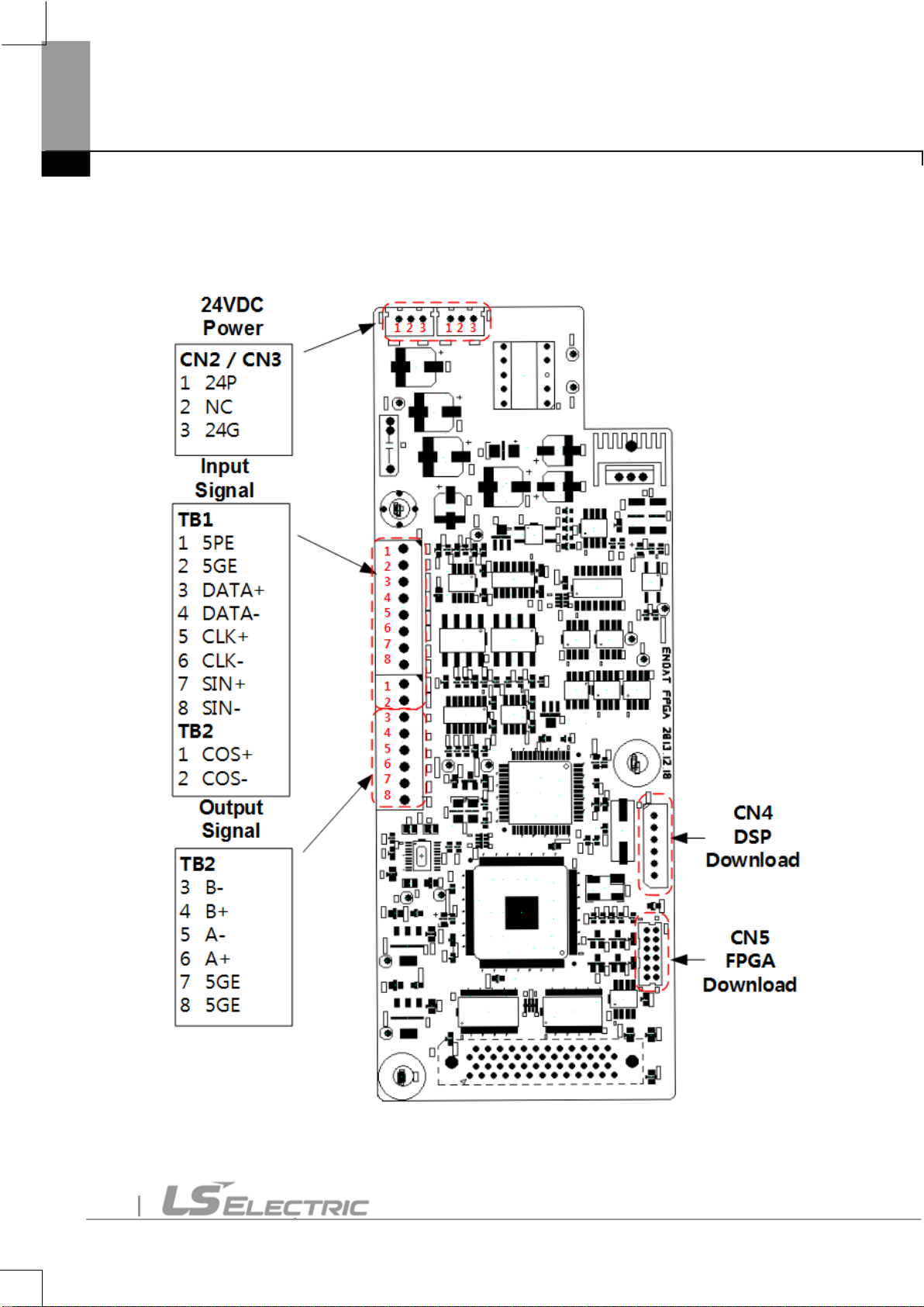
(1) IV5 EnDat option board terminal block .………………………................. 6
(2) Functions of IV5 EnDat option board.……………………………………... 7
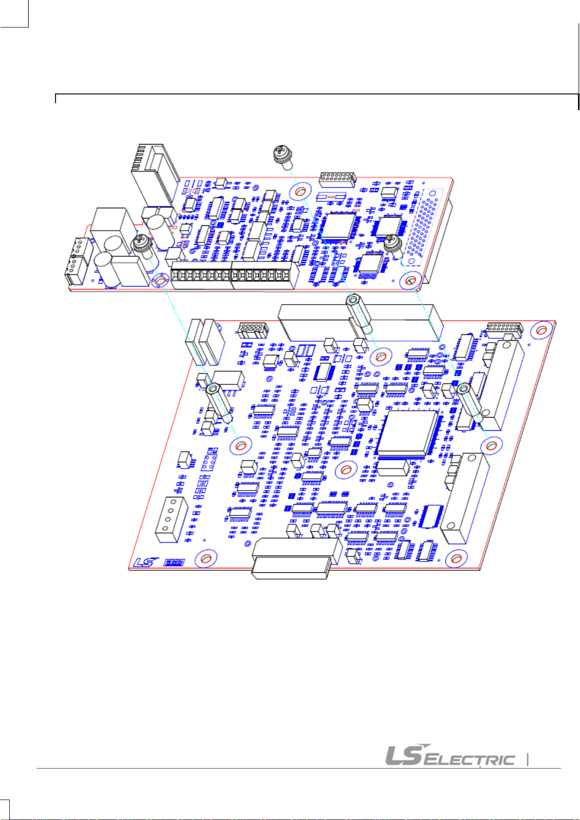
(3) Installation……………...……………………………………………...…......... 9
(4) Connection….………………………....…....……………………...…….........10
(5) Input and output Signal ………....………………...…………………………11
5. Ready for operation
(1) In the case of ECNx13...............................................................................12
(2) In the case of ERNx87...............................................................................12
6. Functions
(1) DIS_01~03(Display EnDat version).........................................................
(2) PAR_10(Pulse count of encoder) ............................................................
(3) PAR_11(Encoder direction setting) .........................................................
(4) PAR_46(Encoder type setting) ................................................................
(5) PAR_47(Encoder tuning selection)..........................................................
(6) PAR_58(EnDat encoder direction setting) .............................................
Reference) Standard Encoder Specification ...............................................................
13
14
14
14
13
13
15

IV5 EnDat Option Manual
4
1. Introdution
IV5 EnDat option board installed in inverter provides informations of motor speed and
angle according to feedback signals of HEIDENHAIN rotary encoder(ECN413, ECN1313,
ERN487, ERN1387).
2. Hardware Specification
Items
Specification
Mounting Type
Fixed by brass stick to the inverter control board
Power Supply
24V External power supply (24P, 24G)
Encoder Power Supply
5V power supply (5PE, 5GE)
Input Signal
DATA+, DATA-, CLK+, CLK-, SIN+, SIN-, COS+, COS-
Encoder Input Pulse Count
2048
Support Encoder
ECN413(EnDat01), ECN1313(EnDat01), ERN487, ERN1387
Output Signal
5GE, A+, A-, B+, B-

IV5 EnDat Option Manual
5
3. Installation and Wiring
A. SV055, 075, 110, 150, 185, 220iV5-2/4(MD)(PM)
R
S
T
G
U
V
W
B1 B2
FX
RX
BX
RST
P1(MM0)
P2(MM1)
P3(ATO)
CM
VREF
AI1
5G
PM
3-phase
AC Input
(440V)
(50/60Hz)
GE
A+
RA
GE
RB
ENC
GE
MCMCCB
FWD Run/Stop Command
REV Run/Stop command
Emergency Stop
Fault Reset
Manual Operation 1
Manual Operation 2
Manual Operation 3
Common
Variable
Resistor
10kΩ, 1/2W
Multi
Function
input
24 V
DB Resistor
(Option)
G
Encoder A-
phase input
Encoder Output A Phase
Note) : Power Terminal Block : Control terminal block
P4(FHM)
P5(BAT)
P6(BRC)
P7(MCC)
STARVERT - iV5
Manual Operation 4
Manual Operation 5
Manual Operation 6
Manual Operation 7
AI2
AI3
Power
Supply(+10V)
Analog input 1
Analog input 2
Analog input 3
Common
Analog input
(10 ~ -10V)
(-10 ~ 10V)
(0 ~ 10V)
(10 ~ 0V)
(0 ~ 20mA)
(20 ~ 0mA)
(Motor NTC)
Encoder B-
phase input
Common (0V)
Encoder Output B Phase
Encoder Output Common
Open Collector
Output
ACR
AO1
AO2
5G
30A
30C
30B
1A
1B
2B
2A
Fault Contact
Output
( ~ AC 250V, 1A)
( ~ DC 30V, 1A)
Multi Fuction
Contact Output
( ~ AC 250V, 1A)
( ~ DC 30V, 1A)
Multi Function
Open Collector
Output
( 24V, 50mA)
OC1
EG
B+
A-
B-
Analog Output 1
Analog Output 2
Common
Analog
Output
(-10 ~ 10V)
(10 ~ -10V)
(0 ~ 10V)
(10 ~ 0V)
AC1
AC2
Control circuit
auxiliary power
(220V)
(50/60Hz)
Isolated transformer
Note)
EnDat
Option
Board
<Main Power Circuit>
<Control Circuit>
5PE
5GE
DATA
CLK
SIN
COS
Note) Multi input terminal block p1 ~ p7: factory default

IV5 EnDat Option Manual
6
4. Control Terminal Block
(1) IV5 EnDat option board terminal block

IV5 EnDat Option Manual
7
(2) Functions of IV5 EnDat option board
Error indication of encoder option board (LED1)
Indication
Name
Description
LED1
Error indication LED of
EnDat option board
As Power supply error of IV5 EnDat option
board, supply 24V power voltage.
※If error occurs repeatedly, it can leave some damages to the product. Please contact with the LS
ELECTRIC website FAQs. (http://www.lselectric.co.kr)

IV5 EnDat Option Manual
8
Input signal of IV5 EnDat option board (TB1, TB2)
Item
Indication
Name
Description
Input
Signal
5PE
5V power supply
Encoder power supply
5GE
0V
DATA+
Communication
DATA Signal
A, B signal of IV5 EnDat option
board. (But it is not necessary to
connect when using ERN487,
ERN1387 encoder.)
DATA-
CLK+
Communication
CLOCK Signal
CLK-
SIN+
Encoder A-phase
Signal
(SIN Signal)
A, B signal of IV5 EnDat option board
PAR_10 (The pulse count encoder)
have to be changed according to
encoder specification. (Refer to 3.
Operation Ready.)
SIN-
COS+
Encoder B-phase
Signal
(COS Signal)
COS-
Connection signal to SIO board (TB2)
Item
Indication
Function
Description
SIO Board
Connection
Signal
5GE
Encoder power supply
0V
A+
Encoder A-phase signal
(Incremental type)
A, B signal of Line Drive type
encoder. Connect to SIO
board with cable.
A-
B+
Encoder B-phase signal
(Incremental type)
B-

IV5 EnDat Option Manual
9
(3) Installation

IV5 EnDat Option Manual
10
(4) Connection
Connect 24V power supply to the option board.
Connect option board input signal to terminal blocks TB1 and TB2.
Connect option board output signal to SIO board.
1. 24V DC
Power
IV5 Control Board
IV5 EnDat Option Board
SIO Board
2.Input signal
5PE/5GE
DATA+/DATA-
CLK+/CLK-
SIN+/SIN-
COS+/COS-
3.Output signal
B-/B+/A-/A+/5GE/5GE
TB1TB2

IV5 EnDat Option Manual
11
(5) Input and output Signal
5PE
Brown/Green
Blue
5GE
White/Green
White
DATA+
Gray
DATA-
Pink
CLK+
Purple
CLK-
Yellow
SIN+
Green/Black
SIN-
Yellow/Black
COS+
Blue/Black
COS-
Red/Black
< Input Signal >
TB1
TB2TB1
5GE
Black
B-
Red
B+
White
A-
Green
A+
Blue
< Output Signal >
TB2

IV5 EnDat Option Manual
12
5. Ready for operation
(1) In the case of ECNx13
- Set PAR_10 to “2048”. PAR_10 is the pulse count of encoder attached to the motor.
- Set PAR_46 to “EnDat”. PAR_46 is Encoder type setting.
- Set PAR_11 to “A Phase Lead” or “B Phase Lead” so that the user defines forward
rotation. PAR_11 is Enc Dir Set.
- Set PAR_58 to CW in the case encoder’s A-phase is SIN input of option board and
encoder’s B-phase is COS input of option board. Change PAR_58 from CW to CCW in
the case encoder’s A-phase is COS input of option board and encoder’s B-phase is SIN
input of option board. PAR_58 is EnDat encoder direction setting.
- Set PAR_47 to “Yes”. PAR_47 is Encoder tuning selection.
- After you have finished setting the parameter of inverter, motor and encoder, set
PAR_47 to “Yes”. Then operate the motor.
- If the motor runs normally from start, you may operate inverter after completing the test.
- If the inverter operate abnormally(inverter trip, overload), then stop the inverter driving
and turn off.And change U-V-W to U-W-V in the connection of inverter and motor.
- Again set PAR_47 to “Yes”and start the motor operation.
(2) In the case of ERNx87
- Set PAR_10 to “2048”. PAR_10 is the pulse count of encoder attached to the motor.
- Set PAR_46 to “SIN/COS”. PAR_46 is Encoder type setting.
- Set PAR_11 to “A Phase Lead” or “B Phase Lead” so that the user defines forward
direction. PAR_11 is Enc Dir Set.
- After you have finished setting the parameter of inverter, motor and encoder, operate
the motor.
- If the motor runs normally from start, you may operate inverter after completing the test.
- If the inverter operate abnormally(inverter trip, overload), then stop the inverter driving
and turn off.And change U-V-W to U-W-V in the connection of inverter and motor.
- Again start to the motor operation.

IV5 EnDat Option Manual
13
6. Functions
(1) DIS_01~03(Display EnDat version)
The Parameter of ‘Sin/Cos EnDat’ displays the version of EnDat option board in
DIS_01~03.
Code
LCD
display
Description
Setting
range
Unit
Setting
DIS_01
~
DIS_03
User disp1
~
User disp3
User-defined
display
-
-
Sin/Cos EnDat
(2) PAR_10(Pulse count of encoder)
In the case pulse count is “2048”, IV5 EnDat option board can be supported.
If you use the encoder of other pulse count, Please contact with the LS ELECTRIC website
FAQs.(http://www.lselectric.co.kr)
Code
LCD
display
Description
Setting
range
Unit
Factory setting
PAR_10
Enc Pulse
Pulse count of
encoder
2048
-
2048
(3) PAR_11(Encoder direction setting)
Set the direction of encoder.
Code
LCD
display
Description
Setting range
Unit
Factory setting
PAR_11
Enc Dir Set
Encoder direction
setting
A Phase Lead/
B Phase Lead
-
A Phase Lead

IV5 EnDat Option Manual
14
(4) PAR_46(Encoder type setting)
“EnDat”and “SIN/COS”are displayed when the IV5 EnDat option board is equipped to
inverter. Set the parameter according to the following table.
Code
LCD display
Description
Setting range
Unit
Factory
setting
PAR_46
Enc Type
Encoder type setting
Normal /
EnDat /
Sin/Cos
-
Normal
(5) PAR_47(Encoder tuning selection)
PAR_47 will be displayed only if you have set encoder type of PAR_46 to "EnDat”. It is
calculated zero point of encoder and offset of motor magnetic pole. If you have installed an
inverter for the first time, or if you have replaced the motor / encoder, you must set PAR_47
to “Yes”. After encoder tuning, it will be set to “No” automatically. After setting PAR_47 to
"Yes", the first operation is the test operation for tuning. Therefore the motor may generate
noise and vibration. During encoder tuning, Anti-Rollback function does not work.
Code
LCD display
Description
Setting range
Unit
Factory
setting
PAR_47
Enc Tuning
Encoder tuning selection
Yes/No
-
Yes
(6) PAR_58(EnDat encoder direction setting)
Set PAR_58 to CW in the case encoder’s A-phase is SIN input of option board and
encoder’s B-phase is COS input of option board. Change PAR_58 from CW to CCW in the
case encoder’s A-phase is COS input of option board and encoder’s B-phase is SIN input
of option board. PAR_58 is EnDat encoder direction setting.
Code
LCD display
Description
Setting range
Unit
Factory
setting
PAR_58
EnDat Dir
EnDat encoder
direction setting
CCW / CW
-
CW
Encoder type
Parameter setting
Remarks
Incremental encoder
Normal
Not use option board
ECN413, ECN1313
EnDat
ERN487, ERN1387
Sin/Cos

IV5 EnDat Option Manual
15
Reference) Standard Encoder Specification
Encoder Signals Specification (HEIDENHAIN encoder)
Interface
Sinusoidal voltage signals 1Vpp
Incremental signals
2 nearly sinusoidal signalsA and B
Signals amplitude M :
Asymmetry |P-N|/2M :
Signal ratio MA/MB :
Phase angle
2/21
:
0.6 to 1.2 Vpp; typ. 1 Vpp
≤0.065
0.8 to 1.25
90˚± 10˚el.
Reference mark signal
1 or more signal peaks R
Usable component G :
Quiescent value H :
Signal-to-noise ratio E, F :
Zero crossovers K, L :
0.2 to 0.85V
0.04V to 1.7V
≥ 40mV
180˚± 90˚elec.
Connecting cable
Cable length
Propagation time
HEIDENHAIN cable with shielding
PUR [4(2ⅹ0.14 mm2) + (4 ⅹ0.5mm2)]
Max. 150m at distributed capacitance 90 pF/m
6 ns/m

IV5 EnDat Option Manual
16
IV5 EnDat .
.
.
.
.
.
.
SV-iV5 EnDat
.
CMOS .
.
.
.

IV5 EnDat Option Manual
17
.
.
unit .
.

IV5 EnDat Option Manual
18
1. ...................... 19
2. .............................. 19
3. ............................. 20
4.
(1) IV5 EnDat .................. 21
(2) IV5 EnDat ............................ 22
(3) .............. 24
(4) .............................................................
(5) ...........................................................
5.
(1) ECNx13 .........................................................................................
(2) ERNx87...........................................................................................
6.
(1) DIS_01~03(EnDat ) .................................................................
(2) PAR_10( ) ..........................................................................
(3) PAR_11( ) ................................................................................
(4) PAR_46(EnDat ) ................................................................................ 29
(5) PAR_47(EnDat ) .......................................................................
(6) PAR_58(EnDat encoder ) .......................................................
) ............................................................................................. 31
25
26
28
28
27
27
28
29
30

IV5 EnDat Option Manual
19
1.
IV5 EnDat iV5 (ECN413,
ECN1313, ERN487, ERN1387)
.
2.
24V . (24P, 24G)
5V (5PE, 5GE)
DATA+, DATA-, CLK+, CLK-, SIN+, SIN-, COS+, COS-
2048
ECN413(EnDat01), ECN1313(EnDat01), , ERN487, ERN1387
5GE, A+, A-, B+, B-
Table of contents
Other LS ELECTRIC Inverter manuals
Popular Inverter manuals by other brands

SPARENERGO
SPARENERGO SE5000U user manual

Scaled Instruments
Scaled Instruments Davis Pro2 Replacement guide

Stel
Stel F20 instruction manual

Hitachi
Hitachi IVX-ES Series Installation and operation manual

Samlex Europe
Samlex Europe SWI 250-12 manual

Generac Power Systems
Generac Power Systems 005261-0 owner's manual