Lucas TVS TVIP1000M12 User manual

TVS Auto Electrics Ltd
Ashroyd Business Park,
Ashroyds Way
Barnsley
S74 9SB
T: 0333 555 0003
W: www.lucastvs.co.uk
EDITION 1
USER
MANUAL
Modified Sine Wave
Inverter

Model Continuous Power Rating Voltage
TVIP1000M12 1000 Watts 12V
TVIP1000M24 1000 Watts 24V
TVIP1500M12 1500 Watts 12V
TVIP1500M24 1500 Watts 24V
TVIP1500M12C 1500 Watts 12V
TVIP1500M24C 1500 Watts 24V
TVIP2000M12 2500 Watts 12V
TVIP2000M24 2500 Watts 24V
TVIP3000M12 3000 Watts 12V
TVIP3000M24 3000 Watts 24V
TVIP4000M12 4000 Watts 12V
TVIP4000M24 4000 Watts 24V
Applicable for the following Models:
This box also contains:
Thank you for purchasing our Lucas TVS Plus Modified Sine Wave Inverter. Please read all
instructions carefully and retain this document for future reference.
Protective Covers
(With models 2000W or higher)
Basic Cable Kit

SAFETY ........................................................................................................1
Safety Declaration........................................................................................1.1
Important Safety Instructions ..................................................................... 1.2
OVERVIEW & FEATURES ............................................................................... 2
What is an Inverter?.................................................................................... 2.1
Modified Sine Wave Inverters .....................................................................2.2
Lucas TVS Plus Modified Sine Wave Inverter Features ...............................2.3
Lucas TVS Plus Modified Sine Wave Inverter Layout ..................................2.4
INSTALLATION & SETUP............................................................................... 3
Load Consideration ..................................................................................... 3.1
Installation Location ...................................................................................3.2
Battery Connection......................................................................................3.3
Earth Connection.........................................................................................3.4
Operation ....................................................................................................3.5
LCD Display .................................................................................................3.6
LCD Display Installation.............................................................................. 3.7
Current Sensor.............................................................................................3.8
LED/LCD Remote Display Codes .................................................................3.9
GENERAL INFORMATION .............................................................................. 4
Specifications.............................................................................................. 4.1
Cabling Recommendations...........................................................................4.2
Maintenance ................................................................................................4.3
Warranty ......................................................................................................4.4
Contents

1 Safety
1.1 Safety Declaration:
This user guide contains information regarding the safe operation of the product within. Failure
to comply can lead to fire, serious injury or death. Lucas TVS will not accept responsibility for any
damage to persons or property caused by failure to comply with the user guide.
1.2 Important Safety Instructions:
• It is recommended that the installation of any inverter be carried out by a qualified
electrician.
• Do not remove the unit cover. Removal of the unit cover will void any further
warranty.
• Do not expose the unit to moisture, as it may cause damage to the unit.
• Keep flammable materials away from the unit as it may become warm during use.
• Do not obstruct the fan ventilation system. Recommended spacing is set at 10cm to
enable adequate ventilation.
• Do not place objects on top of the unit.
• Avoid interfering with the unit, it can become hot during operation.
• Do not expose to direct sunlight for any length of time.
• Keep away from children.
Follow safety instructions with care. Deviating from safety instruction may lead to fire, serious
injury, or death.

2 Overview & Features
2.1 What is an inverter?
An inverter is an electronic device designed to convert Direct Current (DC) to Alternating Current
(AC). DC is the power produced by batteries or solar power, whilst AC is the standard power
required for most electrical equipment.
2.2 Modified Sine Wave Inverters
Modified Sine Wave Inverters (MSW), switch the DC power source between positive and negative
poles in a stepped fashion to give you a simulated sine wave form. See Figure 1:
Modified sine wave inverters are used primarily on heavy duty electrical equipment such as power
tools or electric heaters.
Modified inverters should not be used with sensitive electrical appliances as they may cause
damage, e.g. computers, medical equipment, charging docks or radios.
Figure 1
Current
Time
Modified Sine Wave

2.3 Lucas TVS Plus Modified Sine Wave Inverter Features:
• Durable Design
• Reverse Polarity Protection
• Thermal Protection
• Overload Protection
• Battery-Low Alarm
• Battery-Low Shut-off
• Soft-Start Function
• AC Output Short Circuit Protection
• LED Power Indicator
• LED Fault Indicator
• UK Plug Socket/s*
• LCD Display*
• E-Mark/CE Certified
*See section 4.1 for individual model specifications

A - 230V UK AC Outlet/s
B - Power On/Off Switch
C - Power Indicator
D - Overload Indicator
E - Overheating Indicator
F - LCD Display*
G - Display Port (RJ-11)**
H - Sensor Port (RJ-11)
I - Battery Positive Terminal (+)
J - Battery Negative Terminal (-)
K - Earth Connection
L - Cooling Fans
1000W MODEL
2000W MODEL 3000W - 4000W MODELS 2000W - 4000W MODELS
*Only fitted as standard on 3000/4000W models
**Display port behind LCD on 3000/4000W models
2.4 Lucas TVS Plus Modified Sine Wave Inverter Layout

*Examples only, not to be used for load considerations, power requirements will normally be
found on the appliance or in the user manual.
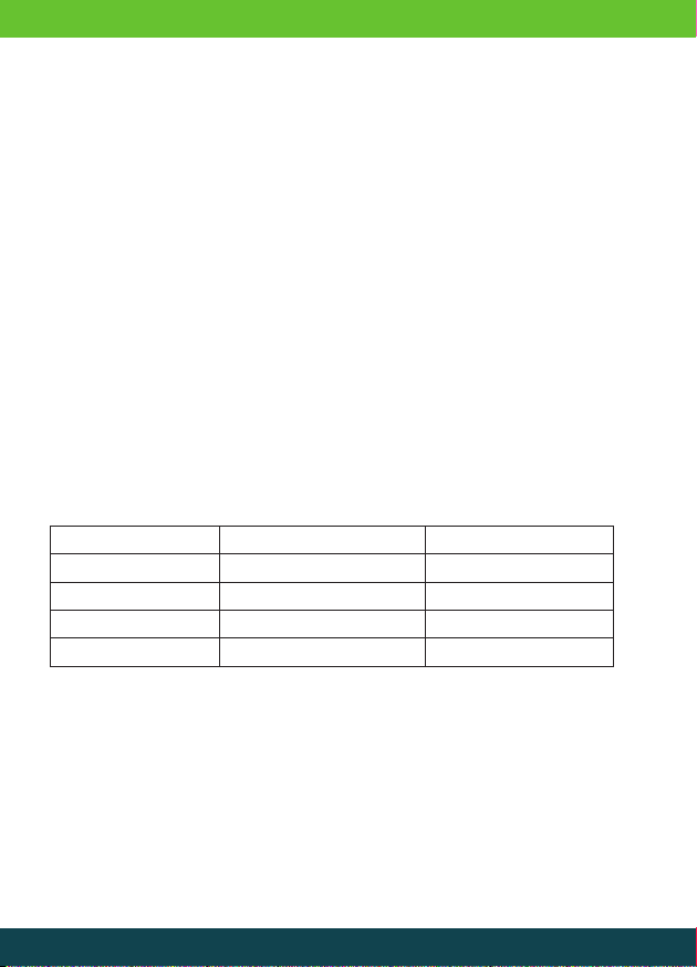
Example* Continuous Load Requirement Starting Load Requirement
Electric Drill 500W 1000W
Microwave Oven 1200W 2400W
Angle Grinder 900W 2700W
Portable Air Compressor 200W 700W
3 Installation and Setup
3.1 Load Consideration:
During the initial start-up of an electrical appliance it will experience a brief increased power
requirement known as the ‘Starting Load’ otherwise commonly known as the ‘Peak Load’.
After the initial starting load, the appliance will begin normal operation which in turn requires
less power, this is referred to as the ‘Continuous Load’.
The starting load within most appliances will generally reach around twice the continuous load,
however this can differ on occasion and be higher.
The units ‘Continuous Power Rating’ is the amount of power the unit can experience during normal
operation. The unit also experiences a ‘Peak Power Rating’ which is the additional amount of
power that can be provided for a short time during the starting load of an appliance.
Should the starting load exceed the peak power rating, or the continuous load exceeds the
continuous power rating the appliance will begin to malfunction.
It is recommended that the user only exploit 80% of the maximum continuous power rating for
ideal operational conditions.
3.2 Installation Location:
The unit is for indoor use only, and as such should only be installed in a cool, dry, dust free and
well-ventilated area. The inverter’s durable casing is designed with mounting points, providing the
option of secure fitting to any flat surface.

3.4 Earth Connection:
Prior to installation and continuously throughout operation, ensure the unit is earthed. This can
be achieved by connecting an Earthing Cable, from the Earthing Bolt* to a suitable earthing point
such as the chassis of a vehicle.
* See section 2.4 for Earthing bolt location
Example of a single battery system:
3.3 Battery Connection:
When connecting the inverter to a battery please ensure you use the correctly rated cables* for
safe and efficient operation.
• Before connecting battery/s ensure the Inverter is switched to the off (O) position
• To help protect the terminals against the risk of short circuit protective covers
should be fitted where provided
• Attach the Black (-) cable to the Black (-) terminal on the rear of the inverter and to
the Black (-) terminal on the battery
• Attach the Red (+) cable to the Red (+) terminal on the rear of the inverter and to
the Red (+) terminal on the battery
• Sparks may be produced when making the battery connection so please ensure
there are no flammable materials present
• To help protect against the risk of a short circuit it is recommended an in-line fuse
(F1 in the diagram below) is fitted on the Red (+) cable, close to the
positive terminal on the battery
*See section 4.2 for cabling recommendations
Caution: Incorrect
connections may cause
damage to the unit, and
therefore will void any future
warranty.
Caution: Do not operate
without earthing the unit,
this may expose the user
to a risk of serious injury
or death.

3.5 Operation
• Check the load requirements* of the appliance do not exceed the unit output.
• Ensure the power switch is in the OFF position (O).
• Plug the appliance into the AC output socket on the unit.
• Turn the power switch to the ON position (I).
• The power indicator will illuminate green (On models with LCD display, the LCD
screen will also activate), the unit will now be providing power from the AC
output.
* See section 3.1 for information on load considerations
3.6 LCD Display:
An LCD Display is fitted as standard on certain models* or can be added as an additional option
to inverters in the Lucas TVS Plus range.
The LCD display provides additional information to help monitor and manage power from the
unit. Using the up/down keys will allow the operator to cycle through the different information
options.
LCD Display
Monitor / Screen
Power On/Off
(Press and hold to turn
inverter on/off)
Select Key
Up/Down Keys

• DC Voltage - the input voltage from the power supply.
• DC Current - the input current being drawn from the power supply in order to
power the appliance**.
• AC Voltage - the output voltage available.
• Output Wattage - the output power being used by any connected appliance/s.
• Hours Remaining - the estimated time remaining before the battery is depleted**.
* See section 4.1 for individual model specifications
** Requires optional current sensor see section 3.8 for more details
By using the LCD display the unit can be configured by entering the ‘Setup’ mode:
• To enter Setup mode press and hold the select key.
• Use the up/down keys to view the different options available.
• Press the select key on the required option, the LCD screen will begin to flash.
• Adjust the setting using the up/down keys and the select key to set.
• To exit the Setup mode press and hold the select key.
• The Last Error Code - Shows any previous error codes (see section 3.9)
• Battery Size - Sets the Ah rating of the battery. When this setting is used in
conjunction with the optional current sensor the LCD Display will also show an
estimate of battery time remaining.
h
3.5
W
AC
0
V
AC
230
DC
A
00.6
DC
V
12.8
P on
A h
500
DC
l 10.5
DC
ER 0
V
V
f 50
23.0
AC
V
!
AC
DC Voltage
DC Current
AC Voltage
Output Wattage
Hours Remaining
Setup Mode Setting Default
Last Error Code N/A N/A
Battery Size
90 - 540 Ah
(In 30Ah steps)
90Ah
Ah
500
ER 0
!

TVIP001RC
To install an LCD display kit please follow the instructions below.
• Ensure the unit on/off switch is on the OFF (O) position.
• Connect the extension lead to the display port on the unit.
• Fit the mounting frame where the LCD display is required.
• Thread the extension cable through the back of the mounting frame and plug into
the port on the back of the LCD display.
• Insert the LCD display into the mounting frame and screw into place.
• Use the snap fit end plates to cover screw fixings.
• Turn the on/off switch on the inverter to the ON (I) position.
• The unit can now be controlled remotely via the LCD display.
The LCD Mounting Kit (TVIP001MK) is available as an additional option for units in the Lucas TVS
Plus range where an LCD display is provided as standard* but may have become inaccessible
after installation.
TVIP001MK
3.7 Installing an LCD Display:
The LCD Display Kit (TVIP001RC) is available as an additional option for units in the Lucas TVS
Plus range where an LCD display does not come as standard*.

TVIP001CS
• Use the snap fit end plates to cover screw fixings.
• Turn the on/off switch on the inverter to the ON (I) position.
• The unit can now be controlled remotely via the LCD display.
* See section 4.1 for model specifications
3.8 Current Sensor:
The Lucas TVS Current Sensor (TVIP001CS) is an additional option that allows the monitoring
of the DC input current and allows the operator to view the estimates hours of battery time
remaining on the LCD Display.
To install an LCD display kit please follow the instructions below.
• Ensure the unit on/off switch is in the OFF (O) position.
• Remove the screws (2) that hold the LCD Display in position.
• Pull the LCD display forward and disconnect the data cable from both the LCD
display and the Display Port on the unit.
• Connect the extension lead to the Display Port on the unit
• Attach the Blanking Plate to the unit, feeding the Extension Cable through the gap,
then screw into position.
• Fix the mounting frame where the LCD display is required.
• Thread the extension cable through the rear of the mounting frame and plug into
the port on the back of the LCD display.
• Insert the LCD display into the mounting frame and screw into place.

(-) (+)
+-
To install a Lucas TVS Current Sensor please follow the instructions below.
1. Using a Black battery cable of the correct rating* attach one end to the battery
negative (-) terminal and the other end to the battery (-) terminal on the
Current Sensor.
2. Using a Red battery cable of the correct rating* attach one end to the battery
positive (+) terminal and the other end to the Positive (+) terminal on the inverter.
3. Using the Load cable (-) supplied, attach one end to the negative terminal (-) on the
Inverter and the other to the current sensor.
4. Using the Comms Cable supplied, attach one end to the comms port on the inverter
and the other to the current sensor.
5. Using the Power Supply Cable supplied, attach one end to the Positive (+) terminal
on the inverter and the other end to the current sensor.
6. Using the Temperature Sensor Cable supplied, attach one end to the battery
negative (-) terminal and the other to the current sensor.
*See section 4.2 for cabling recommendations
FUSE
3.
1.
4. 6.
2.
5.

3.9 Indicator and Display Codes
Power: Illuminates green to show the unit is switched on and
power is available from the AC output socket(s)
Overload: Illuminates red if the unit has been overloaded due to
excessive current or a short circuit
Overheating: Illuminates yellow if the unit has overheated
Audible alarm: An alarm will be heard if the unit has
switched off due to fault
Error Code Description Inverter
Status Actions
-Normal
Operation ON None
Er 1
Battery Low
Voltage
Warning
ON
Check for low battery
voltage. Check cable
connections are not
loose. Reduce load to
extend life.
Er 2
Battery Low
Voltage Shut
Down
OFF Switch inverter off,
recharge battery then
switch back on.
Er 3
Battery High
Voltage Shut
Down
OFF
Check battery voltage is
correct for inverter model
e.g. 24v battery for a 24v
inverter.
Er 4 Overload
Shut Down OFF
Total load exceeded
continuous rating. Start-
up current exceeded
surge rating. Appliance
short circuit fault.
Er 5 Overheating
Shut Down OFF
Check for adequate
ventilation around
inverter. Check inverter
cooling fans are working.
LEDS

4 General Information
4.1 Specifications:
Model Number TVIP1000M12 TVIP1000M24 TVIP1500M12 TVIP1500M24 TVIP1500M12C TVIP1500M24C
Voltage 12V 24V 12V 24V 12V 24V
Continuous
Power Rating
(Up to 12 Hrs)
1000 W 1000 W 1500 W 1500 W 1500 W 1500 W
Peak Power
Rating (Up to
200ms)
2000 W 2000 W 3000 W 3000W 3000 W 3000 W
Output Voltage 230V AC ±10% 230V AC ±10% 230V AC ±10% 230V AC ±10% 110V AC ±10% 110V AC ±10%
Output
Frequency 50Hz 50Hz 50Hz 50Hz 50Hz 50Hz
Output
Waveform
Modified Sine
Wave
Modified Sine
Wave
Modified Sine
Wave
Modified Sine
Wave
Modified Sine
Wave
Modified Sine
Wave
Input Voltage
Range
10V-16V (12V
nom)
20-32V (24V
nom)
10V-16V (12V
nom)
20-32V (24V
nom)
10V-16V (12V
nom)
20-32V (24V
nom)
Input Current 98 A Max 49 A Max 147 A Max 74 A Max 147 A Max 74 A Max
Efficiency at
75% Maximum
Load
> 89 % > 89 % > 89 % > 89 % > 89 % > 89 %
No Load
Current < 0.70 A < 0.45 A < 0.80 A < 0.70 A < 0.80 A < 0.70 A
Low Battery
Alarm 10.5 V (± 0.5 V) 21.0 V (± 0.5 V) 10.5 V (± 0.5 V) 21.0 V (± 0.5 V) 10.5 V (± 0.5 V) 21.0 V (± 0.5 V)
Low Battery
Shut down 10 V (± 0.5 V) 20 V (± 0.5 V) 10 V (± 0.5 V) 20 V (± 0.5 V) 10 V (± 0.5 V) 20 V (± 0.5 V)
Thermal
Protection
Shut down
60°C (±10°C) 60°C (±10°C) 60°C (±10°C) 60°C (±10°C) 60°C (±10°C) 60°C (±10°C)
USB Port No No No No No No
LCD Display No No No No No No
Display Panel
Port Yes Yes Yes Yes Yes Yes
Current Sensor
Port Yes Yes Yes Yes Yes Yes
Dimensions
mm (LxWxH) 300x170x87 300x170x87 360x170x87 360x170x87 410x170x87 410x170x87
Weight 2.8kg 2.8kg 3.4kg 3.4kg 3.5kg 3.5kg
1000W - 1500W

Model Number TVIP2000M12 TVIP2000M24 TVIP3000M12 TVIP3000M24 TVIP4000M12 TVIP4000M24
Voltage 12V 24V 12V 24V 12V 24V
Continuous
Power Rating
(Up to 200ms)
2000 W 2000 W 3000 W 3000 W 4000 W 4000 W
Peak Power
Rating (Up to
12 Hrs)
4000 W 4000 W 6000 W 6000 W 8000 W 8000 W
Output Voltage 230V AC ±10% 230V AC ±10% 230V AC ±10% 230V AC ±10% 230V AC ±10% 230V AC ±10%
Output
Frequency 50Hz 50Hz 50Hz 50Hz 50Hz 50Hz
Output
Waveform
Modified Sine
Wave
Modified Sine
Wave
Modified Sine
Wave
Modified Sine
Wave
Modified Sine
Wave
Modified Sine
Wave
Input Voltage
Range
10V-16V (12V
nom)
20-32V (24V
nom)
10V-16V (12V
nom)
20-32V (24V
nom)
10V-16V (12V
nom)
20-32V (24V
nom)
Input Current 196 A Max 98 Amp 294 A Max 147 A Max 392 A Max 196 A Max
Efficiency at
75% Maximum
Load
> 89 % > 89 % > 89 % > 89 % > 89 % > 89 %
No Load
Current < 0.80 A < 0.55 A < 0.90 A < 0.75 A < 1.0 A < 0.85 A
Low Battery
Alarm 10.5 V (± 0.5 V) 21.0 V (± 0.5 V) 10.5 V (± 0.5 V) 21.0 V (± 0.5 V) 10.5 V (± 0.5 V) 21.0 V (± 0.5 V)
Low Battery
Shut down 10 V (± 0.5 V) 20 V (± 0.5 V) 10 V (± 0.5 V) 20 V (± 0.5 V) 10 V (± 0.5 V) 20 V (± 0.5 V)
Thermal
Protection
Shut down
60°C (±10°C) 60°C (±10°C) 60°C (±10°C) 60°C (±10°C) 60°C (±10°C) 60°C (±10°C)
USB Port No No No No No No
LCD Display No No Ye s Ye s Yes Yes
Display Panel
Port Yes Yes Yes Ye s Yes Yes
Current Sensor
Port Yes Yes Yes Ye s Yes Yes
Dimensions
mm (LxWxH) 340x170x162 340x170x162 420x181x163 420x181x163 420x181x163 420x181x163
Weight 4.6kg 4.6kg 6.6kg 6.6kg 7.5kg 7.5kg
2000W - 4000W

4.2 Cable Recommendations:
The cable recommendations are for reference purposes only, please check with a qualified
electrician before installation. Lucas TVS offers a wide range of cables at different ratings and
lengths, contact your local distributor for more information.
4.3 Maintenance:
Maintenance of the unit is minimal to ensure a working operation. Ensuring the unit is kept clean
regularly with a clean dry cloth to prevent the build-up of dust or dirt. Regularly tighten fixings.
4.4 Warranty:
Lucas TVS promise guarantees this product against any defects in material or workmanship under
recommended operation conditions for a period of 18 months from the date of purchase.
During this time Lucas TVS will aim to repair, replace or refund any unit that proves defective due
to improper material or workmanship while used under recommended operating conditions.
Inverter Model Cable rating Lucas TVS Cable Number
(10 Meter length Black and Red)
TVIP1000M12 110A TCB34B10 + TCB34R10
TVIP1000M24 110A TCB34B10 + TCB34R10
TVIP1500M12 170A TCB36B10 + TCB36R10
TVIP1500M24 110A TCB34B10 + TCB34R10
TVIP1500M12C 170A TCB36B10 + TCB36R10
TVIP1500M24C 110A TCB34B10 + TCB34R10
TVIP2000M12 240A TCB38B10 + TCB38R10
TVIP2000M24 110A TCB34B10 + TCB34R10
TVIP3000M12 345A TCB41B10 + TCB41R10
TVIP3000M24 170A TCB36B10 + TCB36R10
TVIP4000M12 415A TCB42B10 + TCB42R10
TVIP4000M24 240A TCB38B10 + TCB38R10

The guarantee does not include cover for any defects that are not caused as a direct result of
material or workmanship while used under recommended operating conditions.
To raise a warranty, claim please contact the distributor who acted as the point of sale for
further assistance. The distributor will ask for a description of the issue and will require proof of
purchase.
Several examples of issues that will not be covered by the warranty are;
• Fitment not carried out by a qualified electrician.
• Overloading the unit due to incorrect load consideration.
• Opening the unit casing.
• Connecting cables to the incorrect terminals.
• Accidental damage by the operator.
PLEASE NOTE:
Information, images and technical drawings included in this document are the intellectual
property of TVS Auto Electrics Limited.

TVS Auto Electrics Ltd
Ashroyd Business Park,
Ashroyds Way
Barnsley
S74 9SB
T: 0333 555 0003
W: www.lucastvs.co.uk
EDITION 1
USER
MANUAL
Modified Sine Wave
Inverter
This manual suits for next models
11
Table of contents
Popular Inverter manuals by other brands

Sungrow
Sungrow SG15KTL-M Quick installation guide

Generac Power Systems
Generac Power Systems SG30 owner's manual

Whistler
Whistler Pro-1200W owner's manual

Studer
Studer xtender xtm quick guide

Fimer
Fimer TRIO-5.8-TL-OUTD-400 Quick installation guide

Siemens
Siemens MICROMASTER 440 GX Maintenance instructions

Delta Energy Systems
Delta Energy Systems Solivia 30 EU T4 TL Operation and installation manual

Beko
Beko BEHPI 090 owner's manual

Huawei
Huawei SUN2000-3.8KTL-USL0 quick guide

Mitsubishi
Mitsubishi FR-BU2-1.5K instruction manual

Solplanet
Solplanet ASW05kH-T2 Quick installation guide

Renac
Renac R1 Kiddy Series manual