Variable Speed Pump Installation and User’s Guide
iii
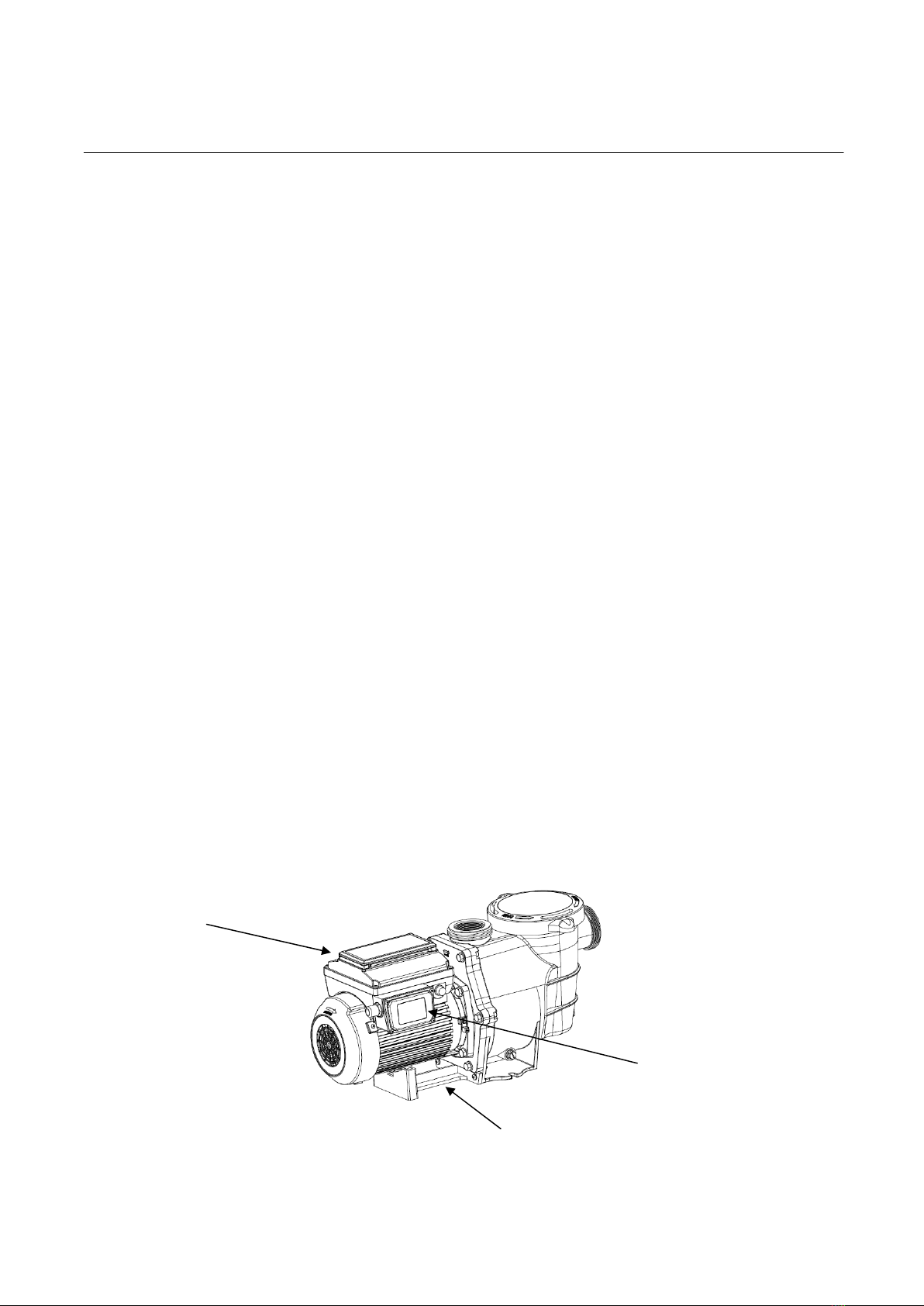
IMPORTANT PUMP
WARNING AND SAFETY INSTRUCTIONS
For Installation of Electrical Controls at Equipment Pa
Switches, Timers and Automation Load Center)
Install all electrical controls at equipm
on/off switches, timers, and control sys
allow the operation (startup, shut-down,
any pump or filter so the user does not pl
portion of his/her body over or near the p
filter lid or valve closures. This installati
allow the user enough space to stand cl
and pump during system start-up, shut
servicing of the system filter.
The Virginia Graeme Baker (VGB) Pool and Spa Safety
requirements for owners and operators of commercial swim
spas.
Commercial pools or spas constructed on or after December
utilize:
(A) A multiple main drain system without isolation capability wit
outlet covers that meet ASME/ANSI A112.19.8a Suction Fittings
Swimming Pools, Wading Pools, Spas, and Hot Tubs and ei
(i) A safety vacuum release system (SVRS) meeting ASME
A112.19.17 Manufactured Safety Vacuum Release syste
for Residential and Commercial Swimming Pool, Spa, Hot
Wading Pool Suction Systems and/or ASTM F2387 Standa
Specification for Manufactured Safety Vacuum Release Sy
for Swimming pools, Spas and Hot Tubs or
(ii) A properly designed and tested suction-limiting vent sys
(iii) An automatic pump shut-off system.
Commercial pools and spas constructed prior to December
single submerged suction outlet shall use a suction outlet c
that meets ASME/ANSI A112.19.8a and either:
(A) A SVRS meeting ASME/ANSI A112.19.17 and/or AS
(B) A properly designed and tested suction-limiting vent
(C) An automatic pump shut-off system, or
(D) Disabled submerged outlets, or
(E) Suction outlets shall be reconfigured into return inlets.
A clearly labeled emergency shut-off s
must be in an easily accessible, obviou
TO MINIMIZE THE RISK OF INJURY
SUCTION ENTRAPMENT HAZARD:
•A properly installed and secured ANSI/ASME A112.19.
anti-entrapment suction cover must be used for each d
•Each suction cover must be installed at least three (3’)
measured from the nearest point to nearest point.
•Regularly inspect all covers for cracks, damage and ad
weathering.
•If a cover becomes loose, cracked, damaged, broken o
replace with an appropriate certified cover.
•Replace drain covers as necessary. Drain covers deteri
time due to exposure to sunlight and weather
•Avoid getting hair, limbs or body in close proximity
cover, pool drain or outlet.
•Disable suction outlets or reconfigure into return inlets.
Mechanical Entrapment: When jewelry, swimsuit, hair decor
or knuckle is caught in an opening of an outlet or drain cover.
present when the drain cover is missing, broken, loose, crack
secured.
NOTE: ALL SUCTION PLUMBING MUST BE INSTALLED I
ACCORDANCE WITH THE LATEST NATIONAL AND LOC
STANDARDS AND GUIDELINES.
Make sure users know where it is and how to use it in cas
ARNING AND SAFETY INSTR
For Installation of Electrical Controls at Equipment Pa
d (ON/OFF
Install all electrical controls at equipment
pad, such as
on/off switches, timers, and control syste
ms, etc. to
r servicing) of
any pump or filter so the user does not pla
ce any
mp strainer lid,
filter lid or valve closures. This installation
should
allow the user enough space to stand clea
r of the filter
or SAVE THESE I
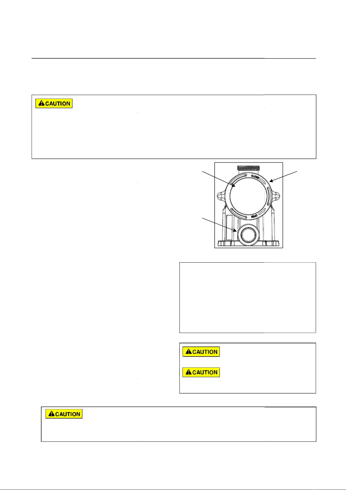
HAZARDOUS PRESS
AND FILTER DURING
Circulation systems
operate under high pressure.
When any part of the
locking ring, pump, filt
er, valves, etc.) is serviced,
air can enter the sys
tem and become pressurized.
Before servicing equipment, make note of t
controls are set to ensure the system cannot i
during service. Turn off all power to the pump.
manual air relief valve in the open position
and wait for all pressure in the
system to be relieved.
Before starting the system, fully open the m
anual air relief valve and place all
system valves in the “open”position to allow
water to flow freely from the
and back to the tank. Stand clear of all equipmen
IMPORTANT: Do not close filter manual air re
has been discharged from the valve and a
appears. Observe filter pressure gauge and
be sure it is not higher than the
pre-service condition
.
Pressurized air can cause the pump housing
cover, filter lid, and valves to
violently separate which can result in sever
e personal injury or death.
Filter tank lid and strainer cover must be prop
erly secured to prevent violent
separation. Stand clear of all circulation syste
turning on or starting up pump.
General Installation Information
•All work must be performed by a qualified
service professional, and
conform to all national, state, and local code
•Install to provide drainage of compartment fo
•These instructions contain information for a
variety of pump models and
therefore some instructions may not apply to
a specific model. All models
are intended for use in swimming pool applic
therefore some instructions may not apply to
a specific model. All models
are intended for use in swimming pool applic
ations. The pump will function
correctly only if it is properly sized to the spe
cific application and properly
installed.
Pumps improperly siz
ed or installed or used in
applications other t
han for which the pump was
intended can result in severe personal injury
or death. These risks may
include but not be limited to electric shock, fir
entrapment or severe injury or property dam
age caused by a structural
failure of the pump or other system compon
The pump can produc
e high levels of suction within
the suction side of
the plumbing system. These high
levels of suction can pose a risk if a person
of the suction openings. A person can be s
this high level of vacuum or may become t
absolutely critical that the suction plumbin
g be installed in accordance
with the latest national and local codes for
The Virginia Graeme Baker (VGB) Pool and Spa Safety Act
creates new
requirements for owners and operators of commercial swimm
ing pools and
Commercial pools or spas constructed on or after December
19, 2008, shall
(A) Amultiple main drain system withoutisolation capability wit
h suction
outlet covers that meet ASME/ANSI A112.19.8a Suction Fittings
for Use in
Swimming Pools, Wading Pools, Spas, and Hot Tubs and ei
ther:
ANSI
A112.19.17 Manufactured Safety Vacuum Release system
s (SVRS)
for Residential and Commercial Swimming Pool, Spa, Hot T
ub, and
Wading Pool Suction Systems and/or ASTM F2387 Standar
d
Specification for Manufactured Safety Vacuum Release Sys
tems (SVRS)
m or
Commercial pools and spas constructed prior to December
19, 2008, with a
single submerged suction outlet shall use a suction outlet co
ver
(A) A SVRS meeting ASME/ANSI A112.19.17 and/or AST
M F2387, or
tem, or
itch for the pump
ust be in an easily accessible, obvious
place.
TO MINIMIZE THE RISK OF INJURY D
UE TO
A properly installed and secured ANSI/ASME A112.19.8 ap
proved
entrapment suction cover must be used for each dr
ain.
cover must be installed at least three (3’) fee
t apart, as
Regularly inspect all covers for cracks, damage and adv
anced
If a cover becomes loose, cracked, damaged, broken or
is missing,
Replace drain covers as necessary. Drain covers deteri
orate over
Avoid getting hair, limbs or body in close proximity to an
y suction
When jewelry, swimsuit, hair decorat
ions, finger, toe
or knuckle is caught in an opening of an outlet or drain cover. T
his hazard is
sing, broken, loose, cracked
, or not properly
NOTE: ALL SUCTION PLUMBING MUST BE INSTALLED IN
ACCORDANCE WITH THE LATEST NATIONAL AND LOCA
L CODES,
Make sure users know where it is and how to use it in case o
f emergency.
IMPORTANT PUMP WARNING AND SAFETY INSTRUC
TIONS
TRUCTIO
E: STAND CLEAR OF PUM
START UP
erate under high pressure.
rculating system (i.e.
locking ring, pump, filte
r, valves, etc.) is serviced,
m and become pressurized.
Before servicing equipment, make note of the
filter pressure. Be sure that all
controls are set to ensure the system cannot ina
dvertently start
during service. Turn off all power to the pump.
IMPORTANT: Place filter
manual air relief valve in the open position
and wait for all pressure in the
Before starting the system, fully open the manua
l air relief valve and place all
system valves in the “open”position to allow wa
ter to flow freely from the tank
and back to the tank. Stand clear of all equipment
and start the pump.
o not close filter manual air rel
ief valve until all pressure
has been discharged from the valve and a s
teady stream of water
Observe filter pressure gauge and be
sure it is not higher than the
over, filter lid, and valves to
violently separate which can result in severe p
ersonal injury or death.
Filter tank lid and strainer cover must be prope
rly secured to prevent violent
separation. Stand clear of all circulation system
equipment when
•All work must be performed by a qualified
service professional, and must
conform to all national, state, and local codes
.
•Install to provide drainage of compartment for
electrical components.
•These instructions contain information for a v
ariety of pump models and
therefore some instructions may not apply to a
specific model. All models
ions. The pump and
therefore some instructions may not apply to a
specific model. All models
are intended for use in swimming pool applicat
ions. The pump will function
correctly only if it is properly sized to the spec
ific application and properly
r installed or used in
for which the pump was
intended can result in severe personal injury o
r death. These risks may
include but not be limited to electric shock, fire,
flooding, suction
caused by a structural
failure of the pump or other system componen
t.
high levels of suction within
the suction side of the p
lumbing system. These high
levels of suction can pose a risk if a person
comes within the close proximi
of the suction openings. A person can be s
eriously injured by
this high level of vacuum or may become tr
apped and drown. It is
absolutely critical that the suction plumbing
be installed in accordance
wimming pools.