Gasboy 9120K Series User manual

QGASBOY
9120K and 9820K Series AST Pumps
Installation and Operation
Manual
MDE-4567C

Computer Programs and Documentation
All
Gasboy
computer
programs
(including software
on
diskettes and within
memory
chips)
and documentation
are
copyrighted
by,
and shall
remain
the
property
of,
Gasboy.
Such
computer
programs
and
documents
may
also
contain
trade
secret
information.
The
duplication,
disclosure,
modification,
orunauthorized
use
of
computer
programs
or
documentation
is
strictly prohibited,
unless
otherwise
licensed by
Gasboy.
Federal Communications Commission (FCC) Warning
This
equipment
has
been
tested and
found
to
comply
with
the
liiiiits
for
a
Class
A
digital
device
pursuant
to
Part
15
of
the
FCC
Rules.
These
limits
are
designed
to
provide
reasonable protection against
harmful
interference when
the
equipment
is
operated
in
a commercial
enViromnent.
This
equipment
generates,
uses,
and
can
radiate
radio
frequency
energy,
and
if
not installed
and
used
in
accordance
with
the
instruction
manual,
may
cause
harmful
interference
to
radio
communications.
Operation
of
this
equipment
in
a
residential
area
is
likely
to
cause
harmful
interference
in
which
case
the
user will
be
required
to
correct
the
interference
at
his
own
expense.
Changes
or
modifications
not expressly
approved
by
the
manufactnrer could
void
the
user's authority
to
operate
this
equipment.
Approvals
Gasboy, Greensboro, is
an
ISO
9001
:2000
registered facility.
Underwriters
laboratories
(Ul):
New York City Fire Department (NYFD): California
Air
Resources Board (CARB):
UL File# Products listed with UL NYFD C
of
A # Product Executive Order# Product
MH4314
All
dispensers
and
self-contained
pumping
4823
9100A,
9140A,
9152A, 9153A,
units
9800A,
9840A,
9850A,
9852A,
Power
operated
Transfer
Pump
Models
25,
9853A,9140
G-70-52-AM
Balance
Vapor
Recovery
G-70-150-AE
VaporVac
MH6418
25C,
26,
27,
28,
72,
72S,
72SP,
72X,
73
and
4997
9822A,
9823A
1820
5046
9100Q, 9140Q,
9152Q, 9153Q,
MH7404
Hand
operated
Transfer
Pump
Models
1230
9800Q, 9840Q,
9852Q, 9853Q
Series,
1243
Series,
1520
and
1720
Series
5087
8753K,
8853K,
9153K,
9853K
MHI0581
Key
control
unit,
Model
GKE-B
Series
(restricted
to
diesel
and
non-
Cardreadertermina1s,Models
1000,
1000P
retail gasoline
sales)
Site
controller,
Model2000S
CFN
Series
5091
8752K,
9152K
Data
entry
terminals,
Model
TPK-900
Series
5129
9122K, 9123K,
9822K,
9823K
Fuel
Point
Reader
System
National Conference
of
Weights and Measures
(NCWM)
-Certificate
of
Compliance (CoC):
Gasboy
pumps
and
dispensers
are
evaluated
by
NCWM
under
the
National
Type
Evaluation Program
(NTEP).
NCWM
has
issued
the
following
CoC:
CoC# Product Model# CoC# Product Model # CoC# Product Model #
95-179
Dispenser
95-136
Dispenser
Patents
9100
Retail
Series,
8700
91-019
Series,
9700
Series
9800
Series
91-057
Gasboy
products
are
manufactnredor sold
under
one
or
more
of
the
following
US
patents:
Dispensers
5,257,720
Point
of
SalelBack Office Equipmeut
D335,673
Dispenser
Controller
Trademarks
Non-registered trademarks Registered trademarks
Atlas'I1.I
Consola'I1.I
JnfinityTId
ASTRA*
Fuel
Point«>
Gasboy«>
Keytrol*
S1im1ine*
This
document
is subject
to
change without notice
..
For information regarding
Gasboy
Literatnre, call
(336)
547-5661
E-mail:
. Internet:
http://www.gasboy.com
©
2008
GASBOY' All
Rights
Reserved
~!~~sCommercial
05-002
Atlas
8700K, 8800K,
9100K, 9200K,
9800K
1000
Series
FMS,
2000S-CFN
Series
Additional
US
and
foreign
patents
pending.
Additional
US
and
foreign
trademarks
pending.
Other
brand
or
product
names
shown
may
be
trademarks
or registered
trademarks
of
their
respective
holders.
~PEls
qEUM
EQlIIPMENT
IN~

Table
of
Contents
1 - Introduction 1
Purpose
..........................................................................
1
General Description
.................................................................
1
Model 9120K
...............................................
1
Model 9820K
...............................................
2
Abbreviations and Acronyms
..........................................................
3
2
-Important
Safety Information 5
3-Wiring
9
Wiring Precautions
.................................................................
9
Ground
..........................................................................
10
Circuit Breakers
...................................................................
10
Pump Motor
......................................................................
10
Pulse Output
.....................................................................
10
RS-485
.........................................................................
11
Wire Size
........................................................................
11
Wire Size Chart
............................................
11
Model 9120K
..............................................
11
Model 9820K
..............................................
11
Conduit
.........................................................................
12
Models 9120K and 9820K
....................................
13
Conduit Size Charts
.........................................
14
Terminal Block ID
.................................................................
15
Wiring Diagrams
..................................................................
15
4 - Control Lines
23
Purpose
.........................................................................
23
Ground
..........................................................................
23
Micro Feed
.......................................................................
23
Micro Neutral
.....................................................................
23
Pump Motor Feed
.................................................................
24
Model 9120K and 9820K
.....................................
24
Neutral Feed
.....................................................................
24
Switch Detect.
....................................................................
24
Slow Flow (Reset Complete/Switch Detect)
.............................................
25
Fast Flow
........................................................................
25
Phase 2 Feed
....................................................................
25
Pulser
.............................................................
"
...........
26
Pulse Output . . . . . . . . . . . . . . . . . . . . . . . . . . . . . . . . . . . . . . . . . . . . . . .
......................
26
RS-485
.........................................................................
26
5 - Installation 27
Installation Precautions
.............................................................
27
Installation DOs
............................................
27
Installation DO NOTs
........................................
28
MDE-4567C 9120K
and
9820KSeries
AST
Pumps Installation
and
Operation Manual· September 2008
Pagei

AST Vent Line "
.................................................................
28
Vapor Recovery Option
............................................................
29
Hose Length Estimatorfor 9820K
....................................................
29
Angle Check Valve
................................................................
30
Typical Installations
...............................................................
31
Base Layouts . . . . . . . . . . . . . . . . . . . . . . . . . . . . . . . . . . . . . . . . . . . . . . . . . . . . . . . . . . . . . . . . . . . . 33
6 - 9820K Setup and Special Features 39
Purpose
........................................................................
39
Electronic Component Access
.......................................................
39
CPU Switch Settings
..............................................................
41
Switch
SW1
...............................................
42
Switch SW2
...............................................
44
Pulser Output Rate Switches
.................................
44
Timeout Switch
............................................
45
Battery Backup Power Supply
.......................................................
46
View/Reset Totalizer
...............................................................
46
Electronic Totalizer
.........................................
46
Mechanical Totalizer
........................................
47
7 - Operating Sequence and Locking the Nozzle 49
Operating Sequence
...............................................................
49
9X20K Nozzle Locking
.............................................................
50
8 - 9820K Startup and Test
53
Installation Completion Checklist
.....................................................
53
Startup
.........................................................................
53
Preliminary Steps
..........................................
53
Startup -Model 9120K
......................................
54
Startup -Model 9820K . . . . . . . . . . . . . . . . . . . . . . . . . . . . . . . . . . . . . . 54
Post Startup Tests
................................................................
54
Voltage
..................................................
54
Tightness. . . . . . . . . . . . . . . . . . . . . . . . . . . . . . . . . . . . . . . . . . . . . . . . . 55
Calibration. . . . . . . . . . . . . . . . . . . . . . . . . . . . . . . . . . . . . . . . . . . . . . . . 55
Power Reset External Adjustment
....................................................
56
Index Index-1
Page
ii
MDE-4567C 9120Kand9820KSeries
AST
Pumps Installation and Operation
Manual·
September 2008

Purpose
Introduction
1-Introduction
Purpose
The
purpose
of
this
manual
is
to
assist Gasboy Authorized Service Contractors (ASCs)
in
installing and operating
the
following units used
with
Aboveground Storage
Tanks
(ASTs):
•
9120K
Compact Mechanical Commercial
pump
•
9820K
Electronic Commercial
pump
Note: Whenever information
in
this document applies
to
all the units listed
above,
the
9X20K
model reference
is
used.
General Description
Model 9120K
The
Gasboy Series 9120K
pump
units
are
UL®-listed.
Note:
NFPA
regulations
do
notallow tank-mountedpumps
to
be usedfor
the
resale
of
fuel.
Model 9120K offers four-wheel mechanical-interlock registers. Mechanical
pump
registers
show
the
total volume
for
a delivery
up
to
999.9
gallons.
The
standard features and specifications of
the
9120K
Series pumps
are
as
follows:
• Discharge elbows
• A 12-foot length
of
hose
• Aworking voltage of
115/230
VAC,
50/60
Hz
• Mechanical
Volume
Totalizer
• A Switch Detect and optional pulser outputs which allow monitoring
of
the
register's
operation when it is connected
to
an automated
fuel
management
system.
• Four-piston, positive-displacement meter
• Belt-driven, positive-displacement rotary-vane
pump
with
an
80
mesh
(300
micron)
strainer and integral air-separation
• Cabinet height of25.4
inches.
The
other dimensions may be
found
on
the
base layout.
• Standard Cabinet fmish has the top, sides,
and
back painted black while
the
front panel
is
painted white.
• Filters
The
available options and accessories
for
the
Gasboy
Series
9120K pumps
are
as
follows:
• Interchangeable Automatic Nozzles
• Pulsers
• Special Lengths
of
Hose
•
Vapor
Recovery System
•
380
VAC
3-Phase Motor
MDE-4567C
9l20K
and 9820KSeries
AST
Pumps Installation andOperation Manual· September 2008
Pagel

Introduction
Model 9820K
Page 2
General
Description
The
Gasboy
Series 9820K Aboveground Storage
Tank
Remote
Access
(ASTRA)
pump
units
are UL-listed.
Note:
NFPA
regulations
do
not allow tank-mountedpumps
to
be
usedfor
the
resale
of
fuel.
The
9820K Series units consist of
two
metal cabinet assemblies.
•
One
assembly
is
mounted on
top
of
the
tank and contains
the
pumping unit,
meter,
electronic pulser,
and
all hydraulics.
The
hose and nozzle
are
connected
to
this
assembly.
•
The
second assembly
is
mounted at aheight
to
permit
easy
access by a
user.
It contains
the
electronic register, controls, display
and
nozzle boot.
The
standard features and specifications
of
the
9820K Series
pumps
are
as
follows:
• One-inch high, 6-digit, backlighted Liquid Crystal Display
(LCD)
•
1000:
1dual-phase, error-checking pulser (gallons);
250:1
dual-phase, error-checking
pulser (liters)
•
AC
authorization
line
for
control
of
the
unit
• Reset complete (Switch Detect) output that allows monitoring
of
the
unit's operation when
it
is
connected
to
an
automated fueling system
• Resettable electronic totalizer
• Discharge elbow
• Both models use a quiet and efficient
pump
which
features
an air eliminator built into the
pump
casting.
The
pump
meter
is
a three-piston, positive displacement meter which
is
tested
and
calibrated for accuracy at
any
speed or pressure
up
to
the
maximum working
pressure
of
50
psi.
•
The
standard pumping cabinet finish
is
white.
The
electronic register cabinet
is
black with
a blue graphics panel.
• Dual
Stage
Solenoid
Valve
• Filter
The
available options and accessories
for
the
Gasboy
Series
9820K pumps
are
as
follows:
• Pulser output
drive
line (open collector), capable
of
driving
1,
10,
100,250 and
500
pulses
per unit (gallons) or
1,
10,
and
100
pulses per unit (liters)
•
RS-485
communication
for
direct connect
to
Gasboy eFN equipment
• Batterybackup
for
display
of
last transaction and capture
of
stored pulse count
in
the
event
ofa power failure.
• Mechanical totalizer
• A working voltage
of
115
VAC
(115/230
for
motor)
60
Hz
for
domestic use,
230
VAC
50
Hz/60
Hz
for
international
use.
• Other options include Listed automatic nozzles, special lengths
of
Listed hose
assembly,
Listed dual swivels, UL-recognized filters,
Vapor
Recovery,
and
Vapor
Recovery
Ready.
MDE-4567C 9120K
and
9820KSeries
AST
Pumps Installation
and
Operation Manual- September 2008

Abbreviations
and
Acronyms
Introduction
Abbreviations and Acronyms
The
following table contains a list
of
abbreviations
and
acronyms used
in
this manual.
Term
Description
AC
(or
ac)
Alternating Current
ASC
Authorized Service Contractor
AST
Aboveground
Storage
Tank
ASTRA
Aboveground
Storage
Tank
Remote
Access
CFR
Code
of
Federal
Regulations
CPR
Cardiopulmonary Resuscitation
CPU
Central Processing Unit
DC
(or
dc)
Direct Current
DIP
Dual
In-line
Package
FPR
Fuel
Point Reader
ICR
Island
Card
Reader
J-Box Junction-Box
LCD
Liquid
Crystal Display
NEC
National Electrical
Code
NFPA
National
Fire
Protection Association
OSHA
Occupational Safety
and
Health
Association
PCB
Printed Circuit
Boards
(preferred
term:
board)
PPG
Pulses Per
Gallon
PPL
Pulses Per Liter
STP
Submerged Turbine
Pump
MDE-4567C 9120Kand 9820KSeries
AST
Pumps Installation and Operation Manual· September 2008 Page 3

Introduction
Abbreviations
and
Acronyms
This
page
is intentionally left blank.
Page 4 MDE-4567C 9120K
and
9820KSeries
AST
Pumps Installation
and
Operation
Manual·
September 2008

Important Safety Information
2-Important Safety Information
This
section introduces the hazards
and
safety precautions
associated
with
installing, inspecting, maintaining or servicing
this
product. Before performing
any
task
on
this product,
read
this
safety information
and
the applicable sections
in
this
manual,
where additional hazards
and
safety precautions for
your task will
be
found.
Fire,
explosion, electrical shock or
pressure release could occur
and
cause
death or serious
injury,
ifthese
safe
service procedures
are
not followed.
Preliminary Precautions
You
are working
in
a potentially dangerous environment of
flammable fuels, vapors,
and
high
voltage or pressures. Only
trained
or authorized individuals knowledgeable
in
the related
procedures should install, inspect, maintain or service this
equipment. .
Emergency Total Electrical Shut-Off
The
first
and
most important information
you
must know
is
how
to
stop all fuel flow
to
the pump/dispenser
and
island.
Locate
the switch or circuit breakers that shut off
all
power
to
all
fueling equipment, dispensing devices,
and
Submerged
Turbine
Pumps
(STPs).
A.
WARNING
The
EMERGENCY
STOP,
ALL
STOP,
and
PUMP
STOP
buttons at the cashier's
station
WILL
NOT
shut offelectrical power
to
the
pump/
dispenser.
This
means
that
even
if
you
activate
these
stops,
fuel
may
continue
to
flow
uncontrolled.
You
must
use
the
TOTAL
ELECTRICAL
SHUT-
OFF
in
the
case
of
an
emergency
and
not the
console's ALL
STOP
and
PUMP
STOP
or
similar
keys.
Total Electrical Shut-Off Before Access
Any
procedure that requires access
to
electrical components
or
the electronics ofthe dispenser requires
total
electrical
shut offofthat unit. Understand the function
and
location of
this
switch or circuit breaker before inspecting, installing,
maintaining, or servicing Gasboy equipment.
Evacuating, Barricading and Shutting Off
Any
procedure that requires access
to
the pump/dispenser or
STPs
requires the following actions:
•
An
evacuation of
all
unauthorized persons
and
vehicles
from
the work
area
•
Use
of safety
tape,
cones
or barricades at the affected
unit
(s)
• A total electrical shut-off of
the
affected unit (s)
Read
the Manual
Read,
understand
and
follow this
manual
and
any
other
labels or
related
materials supplied with this equipment. If
you
do
not understand a procedure,
call
a Gasboy Authorized
Service Contractor or call the Gasboy Service Center
at
1-
800-444-5529.
It
is
imperative
to
your safety
and
the safety of
others
to
understand the procedures before beginning work.
Follow the Regulations
Applicable information
is
available
in
National
Fire
Protection
Association
(NFPA)
30A;
Gode
for Motor
Fuel
Dispensing
Facilities and Repair
Garages,
NFPA
70;
National Electrical
Gode
(NEG),
Occupational Safety
and
Hazard
Association
(OSHA) regulations
and
federal,
state,
and
local
codes.
All
these regulations must
be
followed. Failure
to
install, inspect,
maintain or
service
this equipment
in
accordance with these
codes, regulations
and
standards
may
lead
to
legal
citations
with penalties
or
affect
the
safe
use
and
operation ofthe
equipment.
Replacement Parts
Use
only genuine Gasboy replacement
parts
and
retrofit kits
on
your pump/dispenser.
Using
parts
other
than
genuine
Gasboy replacement
parts
could
create a safety hazard
and
violate local regulations.
Safety
Symbols
and
Warning
Words
This section provides important information about warning
symbols
and
boxes.
Alert Symbol
&
This
safety alerlsymbol is used
in
this manual
and
on
warning labels
to
alert
you
to
a precaution
which
must
be
followed
to
prevent potential personal safety hazards. Obey
safety directives that follow this symbol
to
avoid
possible
injury or
death.
Signal Words
These signal words
used
in
this
manual
and
on
warning
labels tell
you
the seriousness of particular safety hazards.
The
precautions below must
be
followed
to
prevent death,
injury or
damage
to
the
equipment:
It...
DANGER:
Alerts
you
to
a hazard or unsafe practice
~
which
will result
in
death
or
serious
injury.
~
WARNING:
Alerts
you
to
a
hazard
or unsafe practice
• that
could
result
in
death
or serious
injury.
It...
CAUTION with Alert
symbol:
Designates a hazard or
~
unsafe
practice which
may
result
in
minor
injury.
CAUTION without Alert symbol: Designates a hazard
or unsafe practice which
may
result
in
property or
equipment damage
Working
With
Fuels
and
Electrical Energy
Prevent Explosions and Fires
Fuels
and
their vapors will explode or
burn,
ifignited. Spilled
or
leaking
fuels
cause vapors.
Even
filling customer tanks will
cause potentially dangerous vapors
in
the
vicinity ofthe
dispenser
or
island.
MDE-4567C 9120Kand 9820KSeries
AST
Pumps Installation
and
Operation
Manual·
September 2008 Page 5
Important Safety Information
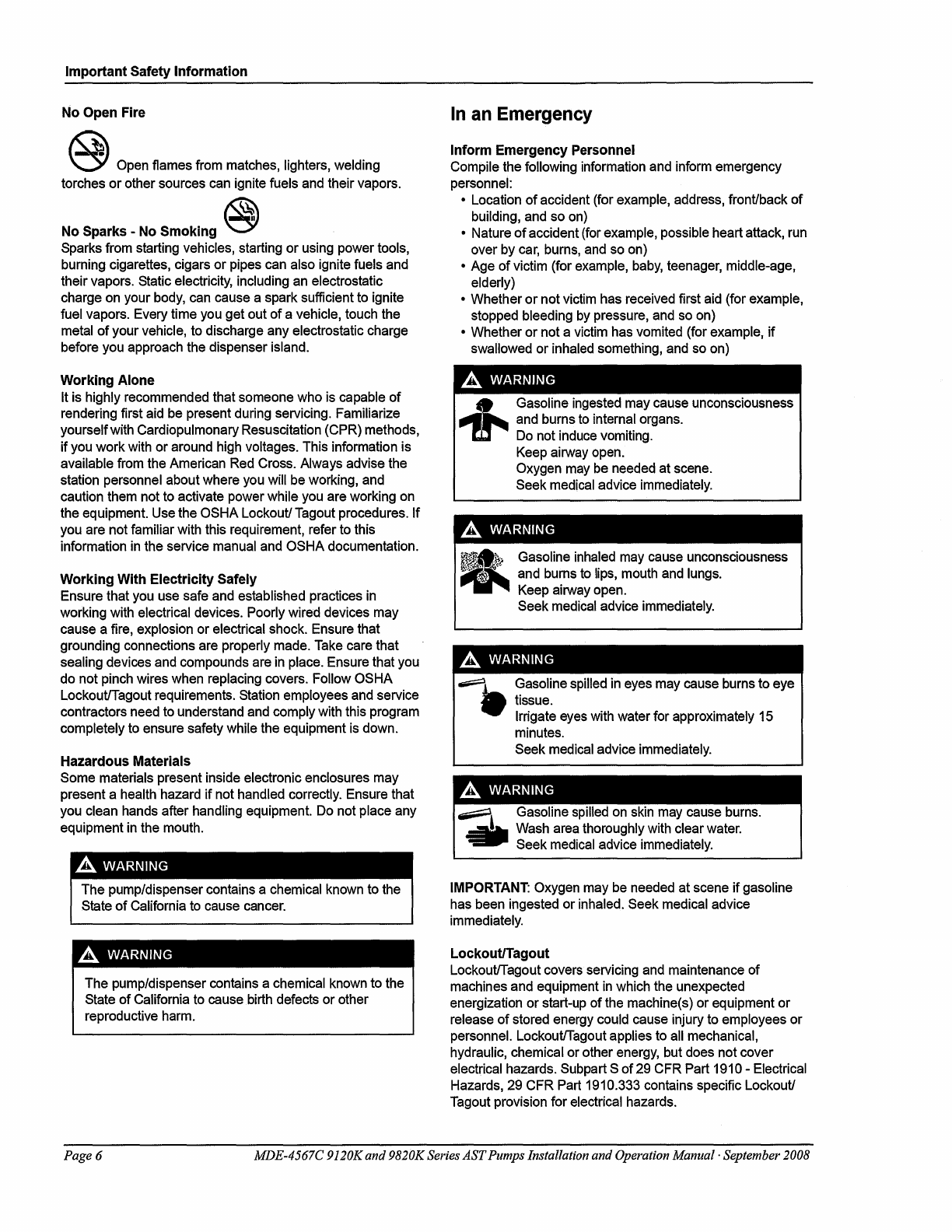
No
Open
Fire
@
Open
flames
from
matches, lighters, welding
torches or other sources
can
ignite fuels
and
their vapors.
~
No
Sparks
-
No
Smoking
\01
Sparks
from
starting vehicles, starting or
using
power tools,
burning cigarettes, cigars or pipes
can
also ignite fuels
and
their vapors. Static electricity, including
an
electrostatic
charge
on
your
body,
can
cause
a spark sufficient
to
ignite
fuel vapors.
Every
time
you
get out ofa vehicle, touch the
metal
ofyour vehicle,
to
discharge
any
electrostatic charge
before
you
approach the dispenser island.
Working
Alone
It
is
highly recommended that someone
who
is
capable of
rendering first
aid
be
present during servicing. Familiarize
yourselfwith Cardiopulmonary Resuscitation (CPR) methods,
if
you
work
with
or around
high
voltages. This information is
available
from
the American
Red
Cross. Always advise the
station personnel about where
you
will
be
working,
and
caution
them
not
to
activate power while
you
are working
on
the equipment.
Use
the OSHA Lockout!
Tagout
procedures. If
you
are
not familiar with this requirement, refer
to
this
information
in
the service manual
and
OSHA documentation.
Working
With
Electricity Safely
Ensure that
you
use
safe
and
established practices
in
working with electrical devices. Poorly wired devices
may
cause a fire, explosion or electrical shock. Ensure that
grounding connections
are
properly
made.
Take
care that
sealing devices
and
compounds
are
in
place. Ensure that
you
do
not pinch wires when replacing covers. Follow OSHA
Lockout/Tagout requirements.
Station
employees
and
service
contractors
need
to
understand
and
comply with this program
completely
to
ensure safety while the equipment
is
down.
Hazardous Materials
Some
materials present inside electronic enclosures
may
present a health hazard if not handled correctly.
Ensure
that
you
clean hands after handling equipment.
Do
not place
any
equipment
in
the mouth.
The pump/dispenser contains a
chemical
known
to
the
State ofCalifornia
to
cause
cancer.
A WARNING
The
pump/dispenser contains achemical
known
to
the
State
ofCalifornia
to
cause
birth
defects or other
reproductive
harm.
In
an
Emergency
Inform
Emergency
Personnel
Compile the following information
and
inform
emergency
personnel:
• Location ofaccident (for example,
address,
front!back of
building,
and
so
on)
• Nature ofaccident (for example, possible heartattack,
run
over by
car,
burns,
and
so
on)
•
Age
ofvictim (for
example,
baby,
teenager,
middle-age,
elderly)
• Whether ornot
victim
has
received first
aid
(for example,
stopped bleeding
by
pressure,
and
so
on)
• Whether or not a
victim
has
vomited (for example, if
swallowed or inhaled something,
and
so
on)
A WARNING
-+-
Gasoline
ingested
may
cause
unconsciousness
and
burns
to
internal
organs.
Do
not
induce
vomiting.
Keep
airway
open.
Oxygen
may
be
needed
at
scene.
Seek
medical
advice
immediately.
A WARNING
Gasoline
inhaled
may
cause
unconsciousness
and
burns
to
lips,
mouth
and
lungs.
Keep
airway
open.
Seek
medical
advice
immediately.
A WARNING
Gasoline spilled
in
eyes
may
cause
burns
to
eye
tissue.
Irrigate
eyes
with
water for approximately
15
minutes.
Seek
medical
advice
immediately.
A WARNING
~1
Gasoline
spilled
on
skin
may
cause
burns
.
..!!!!!II!a.
Wash
area
thoroughly
with
clear
water.
~
Seek
medical
advice
immediately.
IMPORTANT:
Oxygen
may
be
needed
at scene ifgasoline
has
been
ingested or inhaled. Seek medical advice
immediately.
LockoutlTagout
Lockout/Tagout
covers
servicing
and
maintenance of
machines
and
equipment
in
which the unexpected
energization or start-up of
the
machine(s) or equipment or
release ofstored energy
could
cause
injury
to
employees or
personnel. Lockout/Tagout applies
to
all
mechanical,
hydraulic, chemical
or
other
energy,
but
does
not cover
electrical hazards. Subpart Sof
29
CFR
Part
1910
-Electrical
Hazards,
29
CFR
Part
1910.333 contains specific Lockout!
Tagout
provision for electrical hazards.
Page 6 MDE-4567C 9120K
and
9820KSeries
AST
Pumps Installation
and
Operation
Manual·
September 2008

Important Safety Information
Hazards
and
Actions
A WARNING
Spilled
fuels,
accidents involving
pumps/dispensers,
or
uncontrolled
fuel
flow
create
a
serious
hazard.
Fire
or explosion
may
result,
causing
serious
injury ordeath.
Follow established
emergency
procedures.
The
following actions
are
recommended
regarding
these
hazards:
Collision of a
Vehicle
with
Unit
Fire
at Island
•
Do
not
go
near a
fuel
spill or allow
anyone
else
in
the
area.
Fuel
Spill
•
Use
station
EMERGENCY
CUTOFF
immediately.
Turn
off
all
system
circuit breakers
to
the
island(s).
•
Do
not
use
console
E-STOP,
ALL
STOP
and
PUMP
STOP
to
shut off
power.
These
keys
do
not
remove
AC
power
and
do
not always
stop
product
flow.
•
Take
precautions
to
avoid
igniting
fuel.
Do
not
allow
starting ofvehicles
in
the
area.
Do
not allow
open
flames, smoking or power tools
in
the
area.
•
Do
not expose yourself
to
hazardous conditions
such
as
fire, spilled
fuel
or
exposed
wiring.
•
Call
emergency
numbers.
MDE-4567C 9120Kand 9820KSeries
AST
Pumps Installation
and
Operation
Manual·
September 2008 Page 7
Important Safety Information
This
page
is intentionally left blank.
Page 8 MDE-4567C 9120K
and
9820KSeries
AST
Pumps Installation andOperation
Manual·
September 2008

Wiring
Precautions
Wiring
3 -Wiring
Customers
and
installers having
any
questions pertaining
to
the
installation should contact
their Gasboy distributor.
Wiring Precautions
The
quality
of
the electrical installation
is
a major
factor
in
maintaining proper safety levels
and providing trouble-free operation
of
your Gasboy
pump.
To
assure a quality installation,
follow these rules:
I
• All wiring must be installed
to
conform with
all
building/fire codes, all Federal, State, and
Local codes, National Electrical
Code,
NFPA
70,
NFPA
30,
and Automotive and Marine
Service Station
Code
(NFPA
30A)
codes and regulations. Canadian users must
also
comply with
the
Canadian Electrical
Code.
•
Use
only threaded, rigid, metal conduit.
• Use only UL-approved insulated gasoline
and
oil-resistant stranded copper wiring
of
the
proper size.
•
Wire
connections should
be
properly trimmed
and
secured with a wire
nut;
close off
the
open end
of
the
wire nut with electrical tape.
•
The
line
to
the motor should be on a separate circuit
and
installed
on
a
20
to
30
Amp
breaker depending
on
the
motor size andlor
the
voltage setting
and
the
wiring
run.
• Install an emergency power cutoff. In addition
to
circuit breaker requirements ofNFPA
70
and
NFPA
30A, a single control which simultaneously
removes
Alternating Current
CAC)
power
from
all site pumping equipment
is
recommended.
This
control must be readily
accessible, clearly labeled,
and
in
accordance
with
all local
codes.
A WARNING
The DISABLE PUMPS, and STOP buttons at the facility building and the optional
DISABLE PUMPS button on the Island Card Reader (lCR) WILL NOT shut off
electrical power to the pump.
This means that even
if
you activate these stops, fuel may continue to flow
uncontrolled.
You must use the TOTAL ELECTRICAL SHUT-OFF
in
case
of
an emergency and
not only these facility building and ICR station "stops".
In order
to
provide
the
highest level
of
safety
to
you,
your employees,
and
customers, it
is
recommended that all employees be aware
of
the
location
and
are
trained
on
the procedure
for
turning offpower
to
the
entire
system.
MDE-4567C 9120K
and
9820KSeries
AST
Pumps Installation
and
Operation Manual· September 2008 Page 9
Wiring
Ground
Ground
To
ensure proper operation
of
the
equipment
and
provide
the
necessary safety factors,
this
unit
must be grounded. Refer
to
"Ground" on page
23.
Circuit Breakers
A separate circuitbreaker
is
required
for
the motor and another
for
the
rest
of
the unit. A
tag
on
the motor identifies
the
maximum current
draw
of
the
motor.
If
two
(2)
pumps
are
supplied
from
one
breaker,
the
breaker must be capable ofhandling
the
load
of
bothmotors. Provisions
must be made
to
break both legs
of
any
AC
circuit.
Note:
Canadian
regulatory requirements may
differ.
Pump Motor
Pumps
are
shipped
from
the factory with motors wired according
to
the
specifications given
on the order regarding current,
frequency,
and voltage.
Very
often, on installation, it becomes necessary
to
change
the
original setting
to
suit
the
AC
power source.
To
do
this, locate
the
motor changeover plate (typically located
on
the
shaft
end
of
the
motor) and remove
the
screw which secures it
in
place. Slide
the
plate
so
that
the
desired
voltage,
as
marked on
the
plate, lines
up
with
the
screw
hole.
Reinsert
the
screw and secure the
plate
in
place.
Many motor failures result
from
improper setting
of
the
motor changeover plate.
If
set
for
115
VAC
and
a
230
VAC
feed
is
used,
the
motor will bum
out
after running only
for
a short
time.
If
set
for
230
VAC
and a
115
VAC
feed
is
used,
the
motor will run very slowly and
the
starting field will soon bum
out.
Pulse Output
Page 10
The
Pulse Output option provides
the
means
for
an
external system
to
monitor the quantity
that
is
dispensed by
the
9820K pumping unit. Refer
to
"Pulse Output"
on
page
26.
Refer
to
"Wiring Diagrams" on page
15,
along with
the
installation manual
of
the
system that will be
connected
to
the
9820K pumping unit.
MDE-4567C 9120Kand9820KSeries
AST
Pumps Installation
and
Operation
Manual·
September 2008

RS-485
RS-485
Wire Size
Wiring
For information regarding
the
RS-485
option, refer
to
"RS-485"
on
page
26.
Refer
to
"Wiring
Diagrams" on page
15,
along with
the
installation
manual
of
the
CFN
Series System
for
proper
wiring.
The
AC
wire size of
the
Pump
Motor Feed (power supplied
to
unit
for
driving motor),
Pump
Motor (power
from
unit
to
motor), Neutral Feed (Neutral supplied
to
unit
for
driving motor)
and Neutral (power
from
unit
to
the
motor)
is
dependent upon
the
HP
rating
of
the
Pump
Motor,
the voltage
at
which
the
pump
will be operated
(115
VAC
or
230
VAC
International),
and
the
distance
from
the circuit breaker panel
to
the
pump.
In
cases where multiple units
are
powered
from
the
same
breaker through
the
same
wires,
the
gauge
of
the
wires should be increased
to
handle
the
added load according
to
the distance
from
the breaker panel.
The
chart below should be used
as
a guide in selecting
the
proper
wire
size according
to
the
specific installation requirements.
Wire Size Chart
Model 9120K
Model 9820K
115 Volt Wire Gauge Sizes
per
Feet
of
Run
Motor
HP
25' 50' 100' 150'
14
12
10
8
230 Volt Wire Gauge Sizes per Feet
of
Run
1
14
12 12
10
200' 250'
6 6
10
10
300'
4
8
Over 300', Use Relay
at
Motor
Location
The
AC
wire size
for
the
Switch Detect lines must
be
14
AWG
(when they
are
used).
The
Direct Current
(DC)
wire size
for
the Pulser
lines
must be
18
AWG
(when
they
are used).
The
AC
wire
size
for
the
Micro
Feed
and
Neutral should
be
14
AWG.
This
gauge
ofwire will
be sufficient
for
runs
up
to
300
feet
from the breaker panel
to
the
pumping unit. Sites with
distances over
300
feet should
use
12
AWG
wire.
The
AC
wire size
for
the
Slow Flow and Fast
Flow
lines should
be
14
AWG
(when they
are
used).
MDE-4567C 9120Kand9820KSeries
AST
Pumps Installation
and
Operation
Manual·
September 2008 Page
11

Wiring
Conduit
Page 12
Conduit
The
DC
wire size
for
the
Pulser lines connecting
the
pumping unit
to
the
AST
register
assembly must
use
4-conductor,
18
AWG
shielded cable (Belden
89418,
Gasboy
PIN
C08864).
This
cable allows
the
pulser wires
to
run
in
the
same
conduit
as
the
AC
wiring
for
the
short distance between
the
pumping unit and
the
register
assembly.
Belden
89418
is
rated
as
follows:
•
Gas
and
oil-resistant insulation andjacket
•
18
AWG
tinned, stranded, copper
• Four conductors
•
300
Volt
maximum operating voltage
• AluminumlMylar shielded with drain wire
Twisted-pair shielded cable
is
highly recommended
for
the
Pulse Output
or
RS-485
field
wiring (when they
are
used).
This
type
of
cable provides superior noise immunity
and
must
be
used
for
distances over
100
feet or
any
time pulse
output.
RS-485
wiring
is
included in the
same
conduit
as
the
AC
wires. This cable must meet
the
following specifications:
• Conductor:
18
AWG
stranded
wire.
2 twisted-pairs.
•
Shield:
Foil-wrapped
100%
coverage and/or tinned copper braid
90%
coverage
• Drain
Wire:
Stranded, tinned copper,
20
AWG
or larger/or braided shield
•
Voltage
Rating: Maximum operating voltage
of
600V
• Environmental:
Gas
and oil-resistant; suitable
for
wet or dry locations.
Gasboy
can
supply Belden
1063A
(PIN
C09655) which
is
a UL-listed, 4-conductor cable that
meets
the
requirements listed
above.
Note:
Belden
l063A
is
UL-Listed but not
CSA-listed.
Cable with a voltage rating
of
less
than
600
V must be installed in a conduit separate
from
all
AC
wires.
See
the
Gasboy
Fuel Management System Installation Manual
for
specific requirements.
IMPORTANT INFORMATION
All wiring to the Gasboy Series 9x20K pumping unit must be installed
in
threaded, rigid, metal
conduit. PVC IS NOTACCEPTABLE. The GasboyWarrantywill not apply to any pump
in
which the
AC and DC wires are run
in
the same conduit, J-Box
or
wireway, except as noted. The Gasboy
Warranty will not apply to any pump using PVC as conduit.
All
wiring
and
conduit runs must conform with
all
building/fire codes, all Federal, State,
and
Local codes, National Electrical
Code,
NFPA
70,
NFPA
30,
and
Automotive and Marine
Service Station
Code
(NFPA
30A)
codes and regulations. Canadian users must
also
comply
with
the
Canadian Electrical
Code.
Metallic conduit
is
not considered an adequate equipment
ground.
Separate ground wiring
must be used.
MDE-4567C 9120K
and
9820KSeries
AST
Pumps Installation
and
Operation
Manual·
September 2008

Conduit Wiring
Use
the
charts in "Conduit
Size
Charts"
on
page
14
as
a guideline
for
determining
the
necessary conduit sizes
for
wiring
of
the
Gasboy
Series
9120K
and
9820K pumping unit.
When actually determining
the
size
of
conduit, it
may
be necessary
to
increase
the
size
of
conduit because ofa long run or large amount
of
bends.
The
installer should determine
the
orientation
of
the
wire
runs
according
to
the
layout of
the
components
at
the
site and the
applicable Gasboy wiring
diagrams.
Models 9120K and 9820K
It
is
recommended that high voltage
AC
power
wires
to
the register assembly (not between
the
register and pumping unit) be installed in a separate conduit
from
the
DC
pulser output wires
(when used)
and
must not be run
in
any
sort
of
common
conduit or trough.
However,
if
AC
and
DC
power wires share the conduit,
the
DC
wiring must consist
of
UL-
listed cable with
the
specifications described
in
"Wire
Size"
on
page
11.
Only
AC
wires
for
the
system
and
pumps can
be
installed
in
this conduit
for
this application. Wiring between a Fuel
Point Reader
(FPR)
and
its
pre-amp junction box
(J-Box)
is
intrinsically safe
and
must be run
in a conduit with only other intrinsically safe
wiring.
It
cannot be run
in
conduit with
AC,
DC,
RS-485, or pulser wiring, regardless
of
the
cable
type
used.
See
C35628
Fuel Point Reader
Installation
and
Retrofit Manual
for
details.
When the Gasboy Series 9X20K
and
9820K
pumps
are
being installed with a
fuel
management system other than a Gasboy System,
see
the manufacturer installation manual
for
their specific conduit requirements.
Wiring between
the
9820K register
and
pumping unit
is
installed
in
a single conduit.
This
includes the wiring
for
the
AC
control
of
the pumping unit and
the
internal
pulser.
A special
cable,
as
described
in
"Wire Size" on page
11
must be used
for
the connection between
the
pulser inside
the
pumping unit
to
the register
assembly.
MDE-4567C
9l20K
and
9820KSeries
AST
Pumps Installation
and
Operation
Manual'
September 2008 Page 13

Wiring Conduit
Conduit Size Charts
Page 14
To
determine conduit size needed, use
the
THHN/THWN
Wire
Areas
chart (fIrst chart)
to
fmd
the
area
for
each wire
gauge.
Add
up
all wire
areas.
Use
the
Areas
of
Trade
Size
Conduit chart
(second chart)
to
select the smallest number in
the
25%
fIll
area (based on
NEC
501-1) that
comes
closest without exceeding
the
total wire area.
THHNITHWN Wire Areas Diameter Area (square units)
Gauge Inches Millimeters Inches Millimeters
18 0.090 2.29 0.007
4.1
16 0.104 2.64 0.009 5.5
14 0.118 2.95
0.011
6.8
12 0.135 3.43 0.014 9.2
10 0.169 4.29 0.022 14.5
8 0.216 5.49 0.037 23.7
6 0.259 6.60 0.053 34.2
4 0.331 8.41 0.086 55.5
3 0.359 9.14 0.102 65.6
2 0.394 10.01 0.122 78.7
1063A 0.417 10.59 0.137 88.4
Areas
of
Trade-Size Conduit
Internal Diameter Area (square units) Fill Area (square units)
25%
Fill
Trade Size Inches Millimeters Inches Millimeters Inches Millimeters
1/2
0.629 16 0.303 196 0.076 49
3/4
0.826
21
0.532 343 0.133 86
1.063 27 0.862 556 0.215 139
1-1/4 1.378 35 1.50 968 0.375 242
1-1/2
1.614
41
2.04 1314 0.509 329
2 2.087 53 3.36 2165 0.839
541
MDE-4567C 9120Kand9820KSeries
AST
Pumps Installation and Operation
Manual·
September 2008

Terminal
Block
10
Terminal Block ID
The terminal blocks shown below are located
in
the 9820K register assembly.
Figure 3-1: Register Assembly Terminal Block
MICROPROCESSOR
--+_-iJ
FUSE
Wiring Diagrams
CAUTION
1
SLOW
1
~
a:
i?
J
TB2
~
l
POWER
4
TB1
'""<1
7
NEUL~
_ IPULSE/TXil
ti NC/TX-2
«
TB3l:E
GND/RX+3
~
-NC/RX-4
l
SHIELD
5
1MIS
CONNECTOR
IS
INSTALLED
ONLY
WHEN
PULSER
OUTPUT
OR
RS-48S
INTERFACE
IS
SUPPUED
Failure to follow the correct wiring diagram and all listed notes and precautions that follow
each wiring diagram may result in damage to the CPU PCB.
The wiring diagrams provided are as follows:
• Figure 3-2: Model 9120K Wiring Diagrams on page
16
• Figure 3-3: Model 9820K Wiring Diagram -Domestic on page
18
• Figure 3-4: Model 9820K Wiring Diagram -International
on
page 20
MDE-4567C
9l20K
and9820KSeries
AST
Pumps Installation and Operation Manual- September 2008
Wiring
Pagel5

Wiring
Page
16
Figure
3-2:
Model 9120K
Wiring
Diagrams
OPTIONAL
3aDVAC
3·PHASE
MOTOR
WIRING
OPTIONAl.
230
VAC
t,lOTOR
\\IRING
115/230
VAC
WIRING
(10
1
REED
PULSER)
PHASE
2
rEED
115/230
VAC
WIRING
(100
I
ELECTROkIC
PliLSERl
PHASE
2
rEED
@
INDICATES
FlELO
CONNECTION
SEE
tIITE:
3
SEE
IflTE:
3
Wiring
Diagrams
t
10:1
Reed
Pulser
100:1
Electronic
Pulser
MDE-4567C 9120Kand9820KSeries
AST
Pumps Installation and Operation
Manual·
September 2008
This manual suits for next models
1
Table of contents
Other Gasboy Water Pump manuals


Popular Water Pump manuals by other brands

Renkforce
Renkforce 1526585 operating instructions

Pentair
Pentair MYERS SP33 Series Installation, Operation & Parts Manual

Circor
Circor IMO 110 Instruction manual and parts list

Lowara
Lowara TLCN operating manual

DRENO
DRENO DrenoBox 100L Instruction for installation and maintenance

DINKO Instruments
DINKO Instruments D-25VXi manual


Sulzer
Sulzer J 4 Starting and operating instructions

KSB
KSB CHTRa Installation & operating manual

Henden
Henden H62SP Installation & owner's manual

Pfeiffer Vacuum
Pfeiffer Vacuum HiPace 60 P operating instructions

ProMinent
ProMinent gamma/ X GMXa operating instructions

Blue Angel
Blue Angel BCS Operating instructions and parts manual