Excera EP8100 U5 User manual
Digital Portable Radio
Digital Portable Radio
U5

Thanks for your favor in our product. To derive optimum performance from the product, please read this manual carefully
before use.
■ Preface
Warning:
This device complies with part 15 of the FCC Rules. Operation is subject to the following two conditions:
(1) This device may not cause harmful interference, and
(2) this device must accept any interference received, including interference that may cause undesired operation
Changes or modifications not expressly approved by the party responsible for compliance could void the user's authority
to operate the equipment.
For a Class B digital device or peripheral, the instructions furnished to the user shall include the following or
similar statement, placed in a prominent location in the text of the manual:
NOTE: This equipment has been tested and found to comply with the limits for a Class B digital device, pursuant to part
15 of the FCC Rules. These limits are designed to provide reasonable protection against harmful interference in a
residential installation.This equipment generates, uses and can radiate radio frequency energy and, if not installed and
used in accordance with the instructions, may cause harmful interference to radio communications. However, there is no
guarantee that interference will not occur in a particular installation. If this equipment does cause harmful interference to
radio or television reception, which can be determined by turning the equipment off and on, the user is encouraged to try
to correct the interference by one or more of the following measures:
—Reorient or relocate the receiving antenna.
—Increase the separation between the equipment and receiver.

This radio is designed for and classified as “Occupational/Controlled Use Only”, meaning it must be used only during
the course of employment by individuals aware of the hazards, and the ways to minimize such hazards; NOT intended for
use in an General population/uncontrolled environment
–DO NOT operate the radio without a proper antenna attached, as this may damage the radio and may also cause you
to exceed RF exposure limits. A proper antenna is the antenna supplied with this radio by
the manufacturer or an antenna specifically authorized by the manufacturer for use with this radio.
–DO NOT transmit for more than 50% of total radio use time, more than 50% of the time can cause RF exposure
compliance requirements to be exceeded.
–This transmitter may operate with the antenna(s) documented in this filing in Push-to-Talk and body-worn configurations.
RF exposure compliance is limited to the specific belt-clip and accessory configurations as documented in this filing and
the separation distance between user and the device or its antenna shall be at least 2.5 cm.
—Connect the equipment into an outlet on a circuit different from that to which the receiver is connected.
—Consult the dealer or an experienced radio/TV technician for help.

i
Important Information 1
Getting Started 3
Preparing Your Radio for Use 3
Charging the Battery 3
Attaching the Battery 4
Attaching the Antenna 4
Attaching the Belt Clip 4
Checking Items in the Package 2
Radio Controls 5
LED Indicator 6
LCD Icon 6
Menu Navigation 7
Mode 7
Device Information 7
Date and Time 7
Tone 7
Contents
Alert Icon 1
1
LED 7
Display 8
Keypad Lock
8
Vibration 8
Menu Reset
8
Programmable Buttons 8
Noise Reduction 8
Transmit Time-Out 9
Bluetooth 9
GPS 10
Digital Conventional Functions and Operations 11
Call 11
Private Call 11
Group Call 11
All Call 12
Scan 12
Scan Start Condition 12
Scan List 12
Scan Tx Mode 12
Emergency Alarm 14
Emergency Call 14
Priority Channel 1 13
Talkback 13
Priority Channel 2 13
Emergency 14
Scan Delay 13
Message 15
Inbox 15
Disabled Frequencies
12.0 mm
12.0 mm
12.0 mm 12.0 mm

ii
Contents
Group Call 21
Outbox 15
Drafts 15
New Msg 15
Preset Msg 15
Status Msg 15
Color Code 16
Call Log 16
Man Down 16
Zone 16
Analog Conventional Functions and Operations 17
DMO and RMO 17
CTCSS/CDCSS Type 17
CTCSS 17
CDCSS 18
CDCSS Invert
18
Squelch Level 18
Registering 19
Making a Deregistration
19
DMR Trunking Functions and Operations 19
Making a Registration
19
Call 19
Private Call 19 Comprehensive Hunt 28
Emergency Call 24
Broadcast Call 24
Priority Call 24
Forced Group Call 24
Contact 25
Private Call Contact 25
Group Call Contact 25
Redial List 27
Redial or Backdial List 27
New Contact 25
Message 26
Inbox 26
Outbox 26
Drafts 26
Preset Msg 26
New Msg 26
Call Log 27
Status Msg 26
Backdial List
Hunt 28
28
Short Hunt 28
Team Hunt 29

iii
ContentsContents
Priority Call
Call Log 37
Redial or Backdial List 38
Redial List 38
Backdial List 38
Hunt 39
Short Hunt 39
Comprehensive Hunt 39
Team Hunt 39
Background Hunt 39
Team Hunt List 40
Fixed TSCC List 40
TSCC Hunt 40
Channel Information 40
Emergency 41
Optional Accessories 42
Limited Warranty
Troubleshooting 43
Warranty Card 45
44
Subgroup 41
Broadcast Call 37
Team Hunt List
Fixed TSCC List
TSCC Hunt
Channel Information
29
29
29
29
Background Hunt 29
Authentication
Remote Remove Radio Service
Remote Change Radio Service
Emergency
Emergency Call
Emergency Alarm
MPT Trunking Functions and Operations
Registering
Making a Registration
Making a Deregistration
Private Call
All Call
Call
Group Call
Emergency Call
30
30
30
31
31
31
32
32
32
32
32
34
32
36
36
Subgroup 30
37

Important Information
1
■ Alert Icon
Caution:
Indicates situations that could cause human injury or damage to your products.
Note:
Indicates tips that can help you make better use of your products.
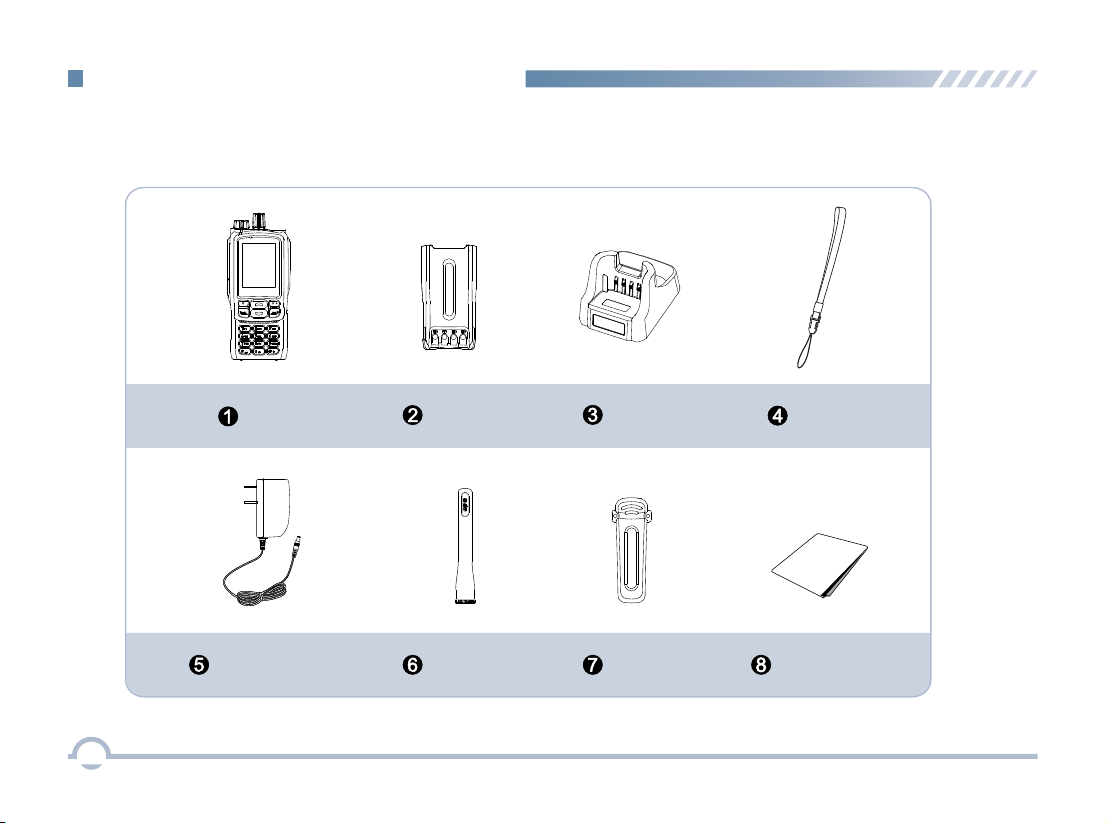
Checking Items in the Package
Please unpack carefully and check that all items listed below are received. If any item is missing or damaged,
please contact your dealer.
Radio Battery
Power Adapter Antenna
Belt Clip
User Manual
Charger
2
Strap
User Manual

LED Indicator
LED Indicator Charger Status
LED flashes red slowly. Standby (no load)
LED glows red. Charging
LED glows orange. 90% charged
LED glows green. Fully charged
LED flashes red rapidly. Failure
■ Preparing Your Radio for Use
Charging the Battery
For best performance, your radio is powered by an Excera
manufactured Lithium-Ion (Li-Ion) battery. To avoid damage
and comply with warranty terms, charge the battery using
the charger contained in the package.
Getting Started
Procedure
Charging Diagram
1. Plug the power adapter into the rear jack of the charger.
See arrow ①.
2. Connect the power adapter to AC socket. See arrow ②.
3. Place the radio with the battery attached, or the battery
alone, into the charger. See arrow ③.
The charging process begins when the charger LED glows red
and is completed when the LED glows green.
1
2
3 3
1
3

Attaching the Antenna
Attaching the Battery
1. Align the battery with the rails on the rear of the radio as
shown by arrow ①.
2. Slide the battery upward to the top of the rails and snap
the latch into place as shown by arrow ②.
To attach the antenna, set the antenna in its receptacle and
turn clockwise.
1
2
To remove the battery, turn off the radio first. Move the
battery latch into unlock position and hold, and slide the
battery down and off the rails.
Getting Started
4
Note: You need to turn off the radio prior to attaching or
removing the antenna.
Attaching the Belt Clip
1. Remove the screws.
2. Align the screw holes on the belt clip with those on the
radio’s body, and then tighten the screws.
To remove the antenna, turn the antenna counterclockwise.
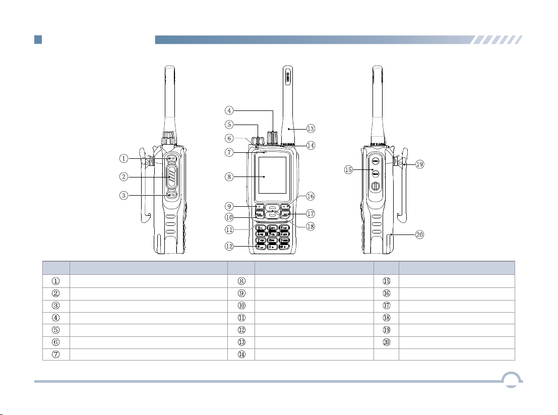
No. Part Name No. No.
Part Name Part Name
SK1 (Side Key 1)
SK2 (Side Key 2)
Radio On-Off/Volume Control Knob
Microphone
Menu/OK Key
Speaker
Antenna
Accessory Jack
Setting Key
P2/End/Home Key
Up/Down Key
Belt Clip
Battery
PTT Key
Channel/Group Call Selector Knob
LED Indicator
LCD Display
P1/Answer/Call Key
Numeric Keypad
TK (Top Key)
■ Radio Controls
Getting Started
5

■ LCD Icon
■ LED Indicator
LED Indicator
Radio Status
LED flashes green slowly. Standby
LED flashes green rapidly. Upgrading or powering on
LED glows green. Receiving
LED flashes red slowly. Low battery
None
Transmitting
LED flashes orange slowly. Scanning
No voice is being transmitted
or received on the traffic
channel after a call is
established. Within such
period, you can hold down
the PTT key to talk.
LED flashes red rapidly.
LED glows red.
LED flashes orange rapidly.
LED glows orange.
None
6
Icon Icon Name
Received Signal Strength
Indicator (RSSI)
New Message Icon/Full
Inbox Icon
Scan Icon
High Power Icon
Low Power Icon
Battery Strength Icon
Roam Icon
GPS Icon
Missed Call Icon
Bluetooth Icon
Wireless PTT
Connected Icon
Bluetooth Headset
Connected Icon
Wireless PTT
and Bluetooth Headset
Connected Icon
B
Getting Started
Accessory Connected Icon
7
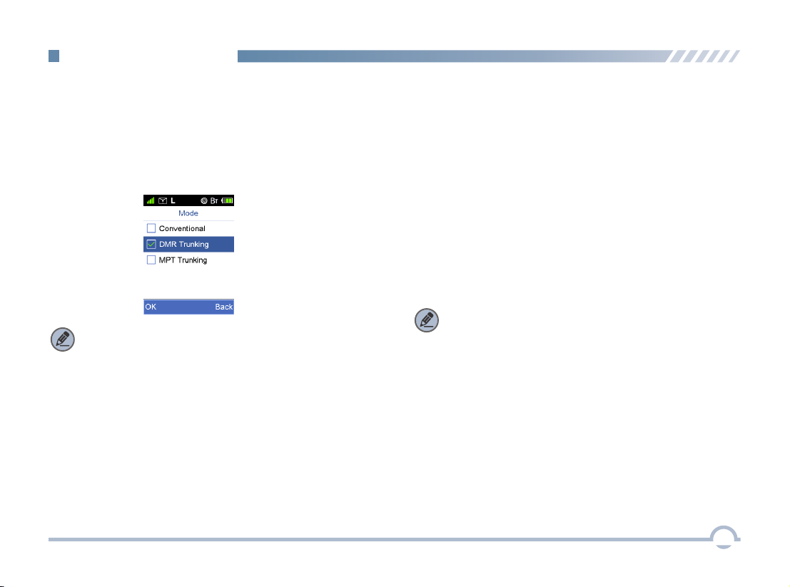
Menu Navigation
Your radio can operate in either of these modes:
Conventional (digital and analog), DMR Trunking, and MPT
Trunking.
To access this item, press the Setting key in home screen
and then select "Function -> Mode".
■ Device Information
■ Tone
With this option, you can view basic information of your radio,
including radio alias, radio ID, serial number, model name,
model number, frequency range, firmware version, data
version, vocoder version, and last programmed date.
To access this item, press the Setting key in the home
screen and then select "Device Information".
This function enables you to set the following tones for your
radio: keypad tone, talk permit tone, incoming call tone,
function tone, warning tone, low battery tone, emergency
alarm tone, and message tone.
To access this item, press the Setting key in the home
screen and then select "General Setting -> Tone".
■ Date and Time
■ Mode
You can set date and time for your radio.
To access this item, press the Setting key in the home
screen and then select "General Setting -> Date and Time".
Note: Select “Conventional” to access digital or analog
conventional mode.
Note: If Function Tone is checked, tone indication will be
given when you enable or switch some functions (such as
toggling power between high and low, and switching zones)
by pressing the programmed buttons.
This option allows you to decide whether to enable LED
indications. You can set the following LEDs for your radio: Tx
LED, Rx LED, Scan LED, Low Battery LED, Incoming Call
LED, and Call Hold LED.
To access this item, press the Setting key in the home
screen and then select "General Setting -> LED".
■ LED

8
■ Display
This option allows you to set display parameters, including
Backlight Off Time, Display Off Mode, and Brightness.
To access this item, press the Setting key in the home
screen and then select "General Setting -> Display".
■ Menu Reset
Your radio supports the menu reset feature. If you do not
operate the menu for a predefined time period, the radio will
automatically return to the home screen.
To access this item, press the Setting key in the home
screen and then select "General Setting -> Menu Reset".
■ Programmable Buttons
You may set the programmable buttons (SK1, SK2, and TK)
as shortcuts to radio functions (such as power level switch,
zone switch, squelch off) using the CPS.
■ Noise Reduction
This option can reduce background noise during
communication so as to enhance voice clarity.
You can set this function via the CPS or the radio menu.
Note:
● This feature is off by default. Keep the microphone
closer to your mouth with this option enabled
because your sound volume will be lower in that
condition.
● This feature is applicable to some radios. For details,
contact your local dealer.
Menu Navigation
■ Keypad Lock
This option allows you to set whether to enable this function.
When Never is unchecked, you can use the Up/Down key to
set the time after which the keypad will be locked.
Press "Menu + " to unlock the keypad.
■ Vibration
This option allows you to set whether to enable the vibration
feature. When this feature is enabled, vibration indication will
be given to an incoming call and a new short message.
You can enable or disable this feature via the CPS or the
radio menu.
To access this item, press the Setting key in the home
screen and then select "General Setting -> Vibration".

9
● When your radio is successfully connected to a wireless
PTT, the wireless PTT connected icon appears on
the status bar.
● When your radio is successfully connected to a Bluetooth
headset and a wireless PTT, the Bluetooth headset and
wireless PTT connected icon appears on the status
bar.
● When your radio is successfully connected to a Bluetooth
headset, the Bluetooth headset connected icon
appears on the status bar.
With the Bluetooth Information option, you can view Bluetooth
headset connection status, wirless PTT connection status,
wirless PTT battery strength, etc.
Menu Navigation
appears on the status bar. You can find a Bluetooth device by
using the Search Devices menu and connect it to your radio.
To access this item, press the Setting key in the home
screen and then select "Accessories -> Bluetooth".
■ Transmit Time-Out
The purpose of Transmit Time-Out is to prevent any user
from occupying a channel for an extended period. If the
preset time expires, the radio will automatically terminate
transmission.
You may set the time via the CPS.
■ Bluetooth
This feature allows you to use your radio with a Bluetooth
-enabled device (such as Bluetooth headset and Wireless
PTT) via a Bluetooth connection.
Note: This function is applicable to some radios.
For details, contact your local dealer. Note:
● If your radio cannot connect to the Bluetooth device,
make sure the device is in pairing mode and then try to
connect your radio to the Bluetooth device via the radio
menu.
● If your radio fails to connect to the Bluetooth device and
the device is in pairing mode, disable and then enable
the Bluetooth feature via the radio menu, and search a
Bluetooth device and connect your radio to this device
via the radio menu.
When the Bluetooth feature is enabled, the Bluetooth icon

Menu Navigation
■ GPS
With this option, you can allow your radio to receive its GPS
information from the GPS chipset and upload the information
to the system after receiving GPS upload request.
To enable or disable this feature, press the Setting key in
the home screen and then select "Accessories -> GPS ->
Position On/Off ".
When the GPS feature is enabled, the icon appears on
the status bar.
If the accurate position of your radio is fixed, the icon
appears on the status bar.
You can check GPS information of your radio by selecting
" Radio Position".
GPS ->
10

Digital Conventional Functions and Operations
■ Call
Private Call
A private call is a call from an individual radio to another
individual radio.
You can make a private call through any of the following
methods.
● Making a Call through Contact or Call Log
Procedure:
1. Press the Menu key to enter the main menu.
2. Go to "Contact -> Private Call Contact", or go to
"Call Log" and access the Missed/Incoming/
Outgoing Call list.
3. Use the Up/Down key to select a private call
contact you want to call.
4. Press the PTT key to make the private call.
● Making a Call via Manual Dial
Procedure:
1. Press the Menu key to enter the main menu.
2. Go to "Contact -> Manual Dial" .
3. Input a private call number using the keypad.
4. Press the PTT key to make the private call.
Group Call
A group call refers to a call from an individual radio to a
group of radios.
You can make a group call through Contact.
Procedure:
1. Press the Menu key to enter the main menu.
2. Go to "Contact -> Group Call Contact".
3. Use the Up/Down key to select a group call contact
you want to call.
4. Press the PTT key to make the group call.
Late Entry
After a group call is established, it allows other group
members to join this call.
Late Entry
After a private call is established, it allows other radios to join
this private call on this channel.
Late Entry may occur in any of the following situations:
● The radio is powered on.
The Channel Selector knob is rotated to the channel ●
in operation.
Your radio is within the communication coverage of ●
this private call on this channel.
To ensure that your speech is clear, keep the microphone
2.5 to 5 cm from your mouth.
11
Late Entry may occur in any of the following situations:

Rx Group List
With this option, you can receive multiple group calls on a
digital channel.
A Rx group list contains a maximum of 64 group calls. You
can set up to 32 Rx group lists using the CPS, each of
which can be associated with a digita channel.
■ Scan
You can start scan only when more than one channel
contained in the scan list.
All Call
An all call is a call from an individual radio to every radio on
the channel.
Note: The All Call ID is fixed.
You can make an all call through Contact.
Scan Start Condition
For the current scan list, you can choose to perform any of
these operations using the Scan List menu: Set as Default,
Set Priority, Add a Channel, and Delete.
To access this item, press the Setting key in the home screen
and then select "Scan -> Scan List".
Scan List
● If a scan list is checked, you can choose to perform any of
these operations in the scan list: Add a Channel, Delete,
and Set Priority.
● If None is checked, the scan feature is disabled.
This option allows you to choose a channel on which the
radio will transmit if you press the PTT key during scanning.
If the Talkback option is disabled (unchecked), the radio will
also transmit on this channel if you press the PTT key during
scan stop.
Scan Tx Mode
Note: You can set and view this feature via the CPS.
● he T radio is powered on.
The Channel Selector knob is rotated to the channel in ●
operation.
T radio exits from another group call.● he
T radio is within the communication coverage of this ● he
group call.
Procedure:
1. Press the Menu key to enter the main menu.
2. Go to "Contact -> Group Call Contact".
3. Use the Up/Down key to select the All Call contact.
4. Press the PTT key to make the all call.
12
Digital Conventional Functions and Operations

Talkback
Note: You can set and view this feature using the CPS.
Priority Channel 1
This option allows you to select a channel in the scan list as
Priority Channel 1. If only Priority Channel 1 is set, 50% of a
radio's scans are on Priority Channel 1 during scanning. If
Priority Channel 2 is set as well, scans for Priority Channel 1
and Priority Channel 2 are 25% respectively.
Priority Channel 2
Note: You can set and view this option using the CPS.
Note: You can set and view this option using the CPS.
Scan Delay
This option enables you to set the time that the radio will
resume scanning after the end of a valid channel activity.
This prevents the radio from resuming a scan immediately
upon the loss of activity.
Note: You can set and view this feature via the CPS.
13
This option allows you to select a channel as Priority
Channel 2. During scanning, 25% of a radio's scans are on
Priority Channel 2 if you have also defined Priority Channel 1.
However, if Priority Channel 1 is set to None, scans for
Priority Channel 2 will be increased to 50%.
Digital Conventional Functions and Operations
With this option enabled, your radio will transmit on the
current channel if you press the PTT key during scan stop.

Procedure:
1. Log in to the CPS.
2. Go to “Conventional -> General Setting” and associate
Emergency On with a programmable button.
3. Go to “Conventional -> Emergency -> Digital Emergency
-> Selected Digital System” and set Emergency Type to
Regular and Emergency Mode to Emergency Call.
4. Press the programmable button to initiate an emergency
call. For example, you can short press the TK on your
radio to initiate an emergency call if you have associated
TK Short with Emergency On.
If the Emergency Call option is selected, your radio only
transmits emergency call upon emergency activation.
You may follow the procedure below to initiate an emergency
call.
Emergency Alarm
If the Emergency Alarm option is selected, your radio only
sends emergency alarm requests upon emergency activation.
You may follow the procedure below to initiate an emergency
alarm.
Procedure:
1. Log in to the CPS.
2. Go to “Conventional -> General Setting” and associate
Emergency On with a programmable button.
3. Go to “Conventional -> Emergency -> Digital Emergency
-> Selected Digital System” and set Emergency Type to
Regular and Emergency Mode to Emergency Alarm.
4. Press the programmable button to initiate an emergency
alarm. For example, you can short press the TK on your
radio to initiate an emergency alarm if you have associated
TK Short with Emergency On.
■ Emergency
Emergency is used to summon help in emergency situations.
Your radio supports two types of emergency modes:
Emergency Alarm and Emergency Call.
Emergency Call
14
Digital Conventional Functions and Operations
Table of contents
Other Excera Portable Radio manuals

Excera
Excera EP3120 U1 User manual

Excera
Excera EP3620 VHF User manual

Excera
Excera EP8100 VHF User manual

Excera
Excera EP8000 VHF User manual

Excera
Excera EP3620 U1 User manual

Excera
Excera EP8100 U1 User manual

Excera
Excera EP5000 User manual

Excera
Excera EP8100 U2 User manual

Excera
Excera EP8000U1 User manual


