Exhale Fans EF34 User manual

Owner's Guide & Installation Manual
MODEL EF34
FANS
To view the LIMITED WARRANTY for this product, visit www.exhalefans.com.
WARNING: Read this manual before using this product. Failure to follow the instructions
and safety precautions in this manual can result in damage to property, serious bodily
injury or death. Keep this manual in a safe location for future reference.
WARNING: This appliance is not to be used by persons (including children) with reduced
physical, sensory or mental capabilities, or lack of experience and knowledge, unless they
have been given supervision or instruction.
WARNING: If unusual oscillating movement is observed, immediately stop using the
ceiling fan and contact the manufacturer, its service agent or suitably qualied parsons.
WARNING: TO REDUCE THE RISK OF FIRE, ELECTRICAL SHOCK, OR INJURY TO PERSONS,
OBSERVE THE FOLLOWING:
a) Use this unit in the manner intended by the manufacturer. If you have questions, contact the
manufacturer.
b) Before Servicing or Cleaning unit, switch power o at service panel and lock the service
disconnecting means to prevent power from being switched on accidentally. When the service
disconnecting means cannot be locked, securely fasten a prominent warning device, such as a
tag, to the service panel.
Protected by one or more of the following US patents: (10,352,325 B2 / D676,543S / D676,952S)
© Exhale Fans, LLC 2018. All rights reserved
Model: EF34
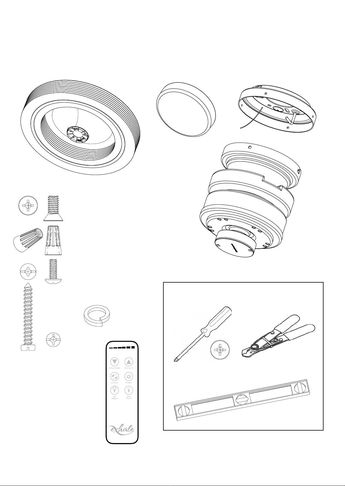
Parts List
Tools Required
Screw Driver
Level
(Magnetic if available)
Wire Strippers
1
1
2
2
3
3
4
4
A A
B B
C C
D D
SHEET 1 OF 1
DRAWN
CHECKED
QA
MFG
APPROVED
nhiner 5/17/2013
DWG NO
TITLE
SIZE
C
SCALE
REV
Exhale Fan (Prebuilt)
Dust Cover &
LED Light
DC Motor
Flat Head Motor Screws (1/4-20)
Qty: 5
Ceiling Mount
Motor Mount Screws (#10-24)
Qty: 4
Wire Nuts
Qty: 3
Misc Ceiling
Mounting
Screws
Qty: 4
Lock (Vibration)
Washers
Qty: 4
Wireless Remote
FANS
Protected by one or more of the following US patents: (10,352,325 B2 / D676,543S / D676,952S)
© Exhale Fans, LLC 2018. All rights reserved
FANS
Safety First!
∞To reduce the risk of electric shock, ensure electricity
has been turned o at the circuit breaker or fuse box
before beginning any installation procedures.
∞All wiring must be in accordance with local electrical
codes. Electrical installation should be performed by a
qualied licensed electrician.
∞WARNING: To reduce the risk of electrical shock
and re, do not use this fan with any speed
control device other than the included wireless
remote.
∞The outlet box and support structure must be securely
mounted and capable of supporting a minimum of 50
pounds. Use only certied outlet boxes marked FOR
FAN SUPPORT.
∞WARNING To reduce the risk of re, electrical
shock or personal injury, only mount fan to
outlet box marked ACCEPTABLE FOR FAN
SUPPORT.
∞To avoid personal injury or damage to the fan and other
items, be cautious when working around or cleaning
the fan.
∞Do not use water or detergents when cleaning the fan
or fan discs. A dry dust cloth or lightly dampened cloth
will be suitable for most cleaning.
∞After making electrical connections, spliced conductors
should be turned upward and pushed carefully into the
outlet box.
∞Electrical diagrams are for reference only.
∞WARNING: To reduce the risk of personal injury,
use only the two steel screws (and lock washers)
provided with the outlet box for mounting to
the outlet box. Most outlet boxes commonly
used for lighting xtures are not acceptable
for fan support and may need to be replaced,
consult a qualied electrician if in doubt.
∞WARNING: This appliance is not to be used
by persons (including children) with reduced
physical, sensory or mental capabilities, or lack
of experience and knowledge, unless they have
been given supervision or instruction.
∞Children (even supervised) should not play with the
appliance.
∞The Exhale Fan should be installed above the
oor at a height in accordance with local codes.
∞The replacement of parts of the safety suspension
system device shall be performed by the manufacturer,
its service agent or suitably qualied persons.
∞The xing means for attachment to the ceiling such as
hooks or other devices shall be xed with a sucient
strength to withstand 4 times the weight of the ceiling
fan.
∞The mounting of the suspension system shall be
performed by the manufacturer, its service agent or
suitably qualied persons.
∞Users are advised to contact the fan supplier to
conduct regular examination of the fan suspension
system at least once in every two (2) years.
∞All attachments of the fan suspension/
mounting hardware system are provided and
designed to be vibration proof. The mounting
screws are supplied with Lock/Vibration
washers that prevent each attachment point
from loosening while the fan is in operation.
∞For installation in the Country of Singapore.
The fan and its installation in particular
the Suspension/Mounting System shall be
Inspected/Examined at least once every two (2)
years.
∞WARNING: To reduce the risk of personal
injury, install fan at least 2.3 m. (7 ft.) or more
above the oor.
PLEASE READ AND SAVE THIS INSTALLATION MANUAL completely before you begin to install the Exhale™ Fan.
You will be happy you did.
To view the LIMITED WARRANTY for this product, visit www.exhalefans.com.
Protected by one or more of the following US patents: (10,352,325 B2 / D676,543S / D676,952S)
© Exhale Fans, LLC 2018. All rights reserved
Model: EF34
Installation
Step 1. Determine the location
The preferred location for the EF34 is in the center of the room, this position will provide the best performance of
the fan.
If you intend to place multiple fans in the same room you should divide the room into equal sections and place
the fans in the center of each section. In both instances of one or multiple fans, the above recommendations will
provide air movement coverage to all corners of the space.
∞WARNING: To reduce the risk of re, electrical shock or personal injury, only mount fan to outlet box
marked ACCEPTABLE FOR FAN SUPPORT.
Step 2. Remove contents from the package
The 2-part protective foam covers the entire fan and through the hand hole openings lift the top cover from the
box. Located in each corner of the protective foam you will nd all the parts located in form tting slots. Included
are the DC motor, mounting hardware, remote, and LED light. Carefully remove each individual part ensuring that
all the parts are cross-referenced with the “Parts List” located in the front of this document.
Do not remove the body of the Exhale™ Fan at this time; that will come later in the installation.
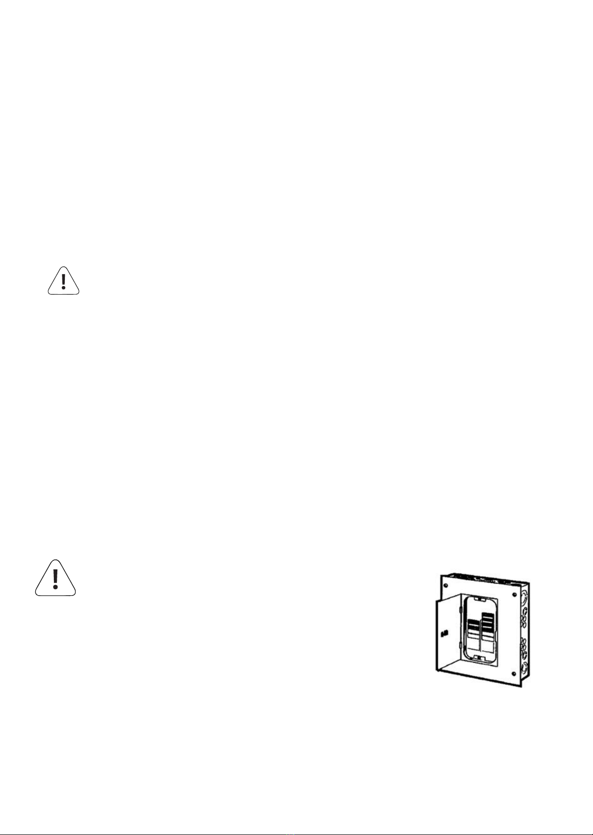
Step 3. Turn o all electrical power
Locate your electrical panel or fuse box and turn o the power to the room where you are installing the fan.
WARNING: TO REDUCE THE RISK OF FIRE, ELECTRICAL
SHOCK, OR INJURY TO PERSONS, OBSERVE THE
FOLLOWING:
a) Use this unit in the manner intended by the manufacturer. If
you have questions, contact the manufacturer.
b) Before Servicing or Cleaning unit, switch power o at service
panel and lock the service disconnecting means to prevent
power from being switched on accidentally. When the service
disconnecting means cannot be locked, securely fasten a
prominent warning device, such as a tag, to the service panel.
Protected by one or more of the following US patents: (10,352,325 B2 / D676,543S / D676,952S)
© Exhale Fans, LLC 2018. All rights reserved
FANS
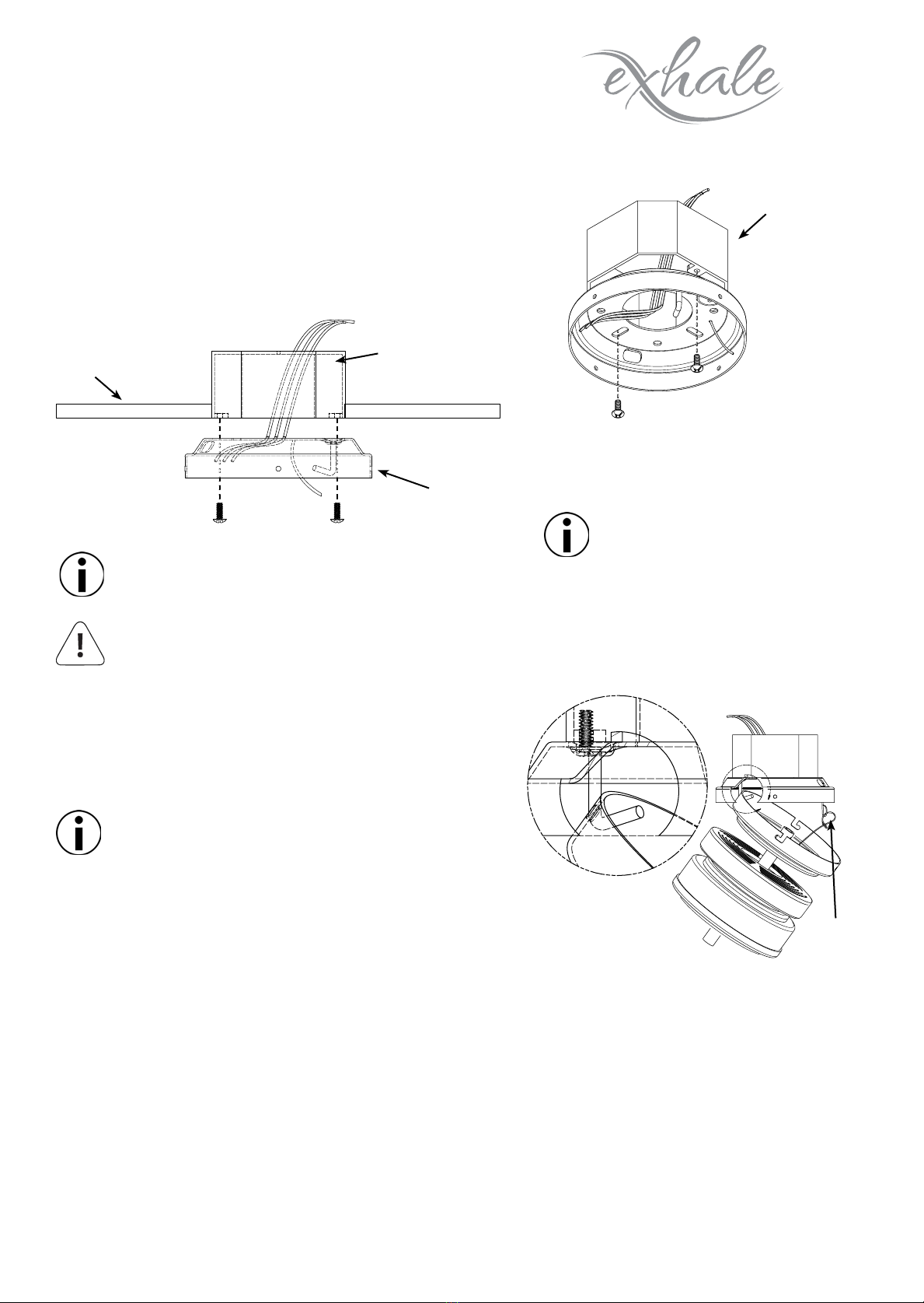
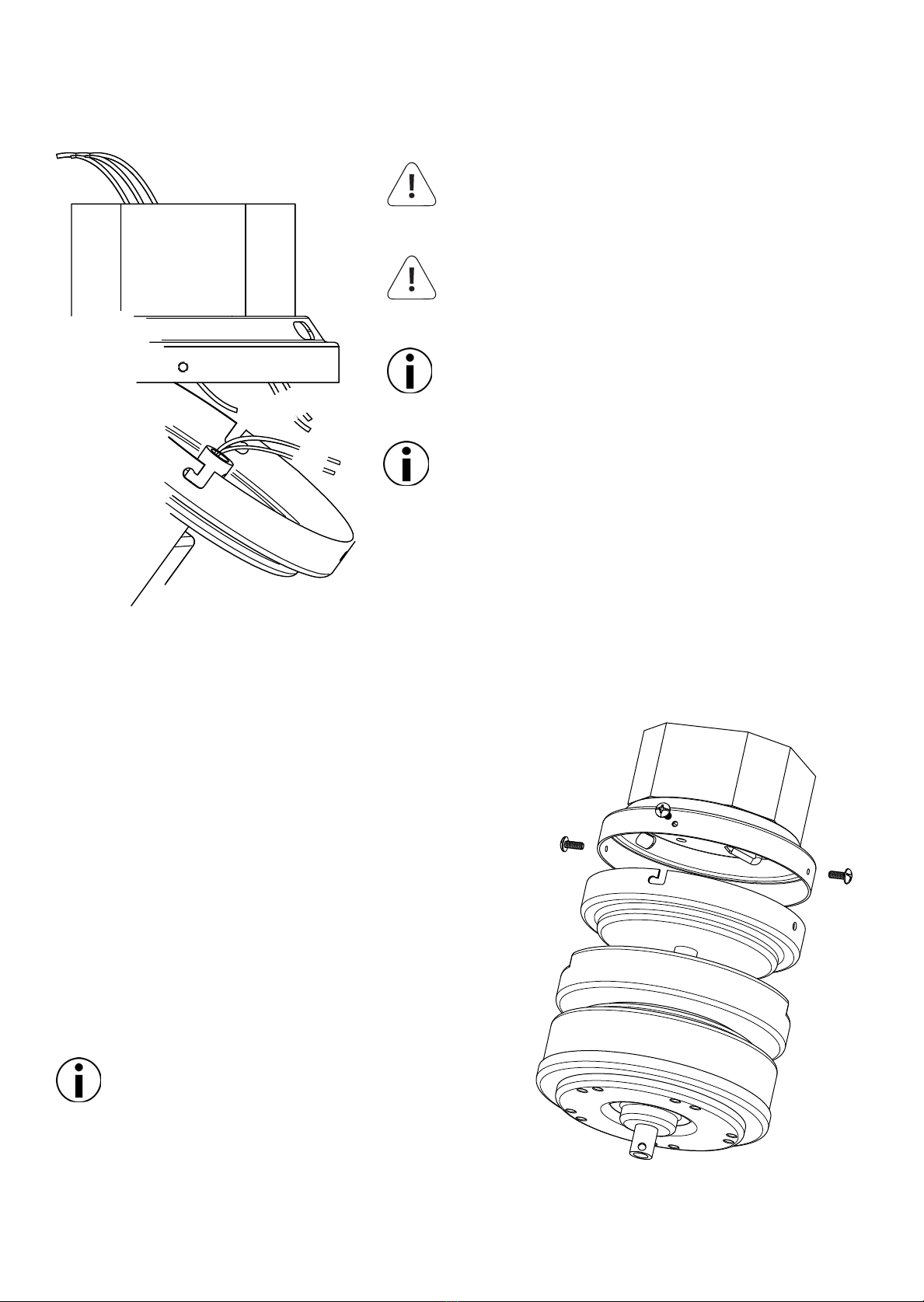
Step 4. Ceiling Mount
a. Pass the electrical wires from the ceiling through the ceiling
mount center hole as shown in Figure 1.
b. Secure the ceiling mount to the junction box
using the
hardware supplied with the junction box
as shown in Figure 2.
c. Using a level, make sure the mount is
plumb and level to the oor, adjust if
necessary.
Figure 1.
Junction Box
(Fan Rated)
Step 5. Electrical Connections
a. Connect the fan supply
(Black) wire to the black
household supply wire as
shown in Figure 4.
b. Connect the neutral fan
supply (White) to the white
household supply as shown
in Figure 4.
Start by hanging the motor from the ceiling mount hook as
shown in Figure 3.
Installation to concrete ceilings requires optional
mounting hardware. (See Optional Accessories A)
Junction Box (Fan
Rated)
Ceiling Mount
Ceiling
Figure 2.
Figure 3.
B
Safety Cable
and Hook
WARNING: Not using the hardware included with the junction box could result in a weak connection of
the ceiling mount to the junction box and cause the fan to become unstable or fall.
Running the Exhale out of level
can cause it to become unstable
or wobble.
Note: Your motor may be supplied with wiring colored
Red and Black or Black and White. For the Red and Black
colored wire pair, the Red wire is Line and the Black wire
is Neutral. For the Black and White colored wire pair, the
Black wire is Line and the White wire is Neutral.
c. Connect the Ground fan
wire (Green) to the ground
household supply as shown in
Figure 4.
d. After connecting all the wiring,
spread them apart so that
the Green and White wires
are located on one side of the
electrical box and the Black on
the other.
e. Turn the wire nuts upward and
push the wires neatly into the
electrical box so they are out of
the way.
f. Secure the fan safety cable
hook through the slot on the
ceiling mount that is opposite
of the ceiling mount hook.
Protected by one or more of the following US patents: (10,352,325 B2 / D676,543S / D676,952S)
© Exhale Fans, LLC 2018. All rights reserved
Model: EF34
Figure 4.
Step 6. Mounting the Motor
Pre-install 2 of the included #10-24 screws half-way into the
ceiling mount on either side.
Install the motor onto the ceiling mount by sliding the pre-
installed bottom mount over the ceiling mount as shown in
Figure 5.
Using a clockwise twisting motion, the motor will temporarily
lock into the ceiling mount while you install the remaining 2 #10-
24 screws and tighten all connections.
Be sure an align the two twist lock channels with
the 2 pre-installed screws added rst.
Figure 5.
WARNING: To reduce the risk of electrical shock, DO NOT
use a wall-mounted speed control with this fan. It WILL
permanently damage the electronic circuitry.
WARNING: Turn o all electrical power prior to making
any electrical connections. Failure to do so could result in
electrical shock, personal injury, or death.
Use the wire connecting nuts supplied with your fan.
Secure the connectors with electrical tape.
Make sure there are no loose strands or connections.
The external earth conductor wire should be longer than
both the Line and Netural wires.
If you are unsure how to disconnect the electric power, or feel that
you do not have enough electrical knowledge, please consult a
licensed electrician for assistance.
If the installation uses the supplied expansion anchors or the
installation is in the Country of Singapore refer to the page in
this manual on Concrete Mounting Hardware under Operational
Accessories.
Household Supply
Black
White
Black
White
Ground
Protected by one or more of the following US patents: (10,352,325 B2 / D676,543S / D676,952S)
© Exhale Fans, LLC 2018. All rights reserved
FANS
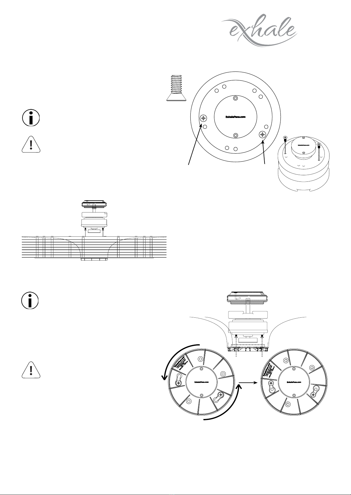
Step 7. Hanging the Disc Array
a. Using only (2) of the included 1/4-20 at head
motor mount screws, install them (2) full
rotations as shown in Figure 7.
Note: These screws will be tightened
completely in a later step.
Figure 7.
Install (2) motor mount screws 2 full
turns into the motor. The locations for
the screws are marked with a small
white mark.
WARNING: Not installing the screws a
full (2) rotations could result in them
backing out and causing the disc array
to fall prior to installing the remaining
screws.
b. Install the disc array onto the motor by aligning
the (2) screws installed earlier to the 'Key Holes'
in the disc array as shown in Figure 9.
c. Rotate the entire disc array counter clockwise to
lock the screws into the disc array as shown in
Figure 9.
Figure 8.
Note: The disc array should be free
hanging from the (2) mounting screws.
d. Install the remaining (3) screws into the disc
array tightening all (5) using an alternating
pattern to ensure an even pressure is put
on all screws.
Figure 9.
WARNING: Not tightening the
motor mounting screws properly
could result in a weak connection
of disc array to the motor and
cause the fan to become unstable
or fall.
Protected by one or more of the following US patents: (10,352,325 B2 / D676,543S / D676,952S)
© Exhale Fans, LLC 2018. All rights reserved
Model: EF34
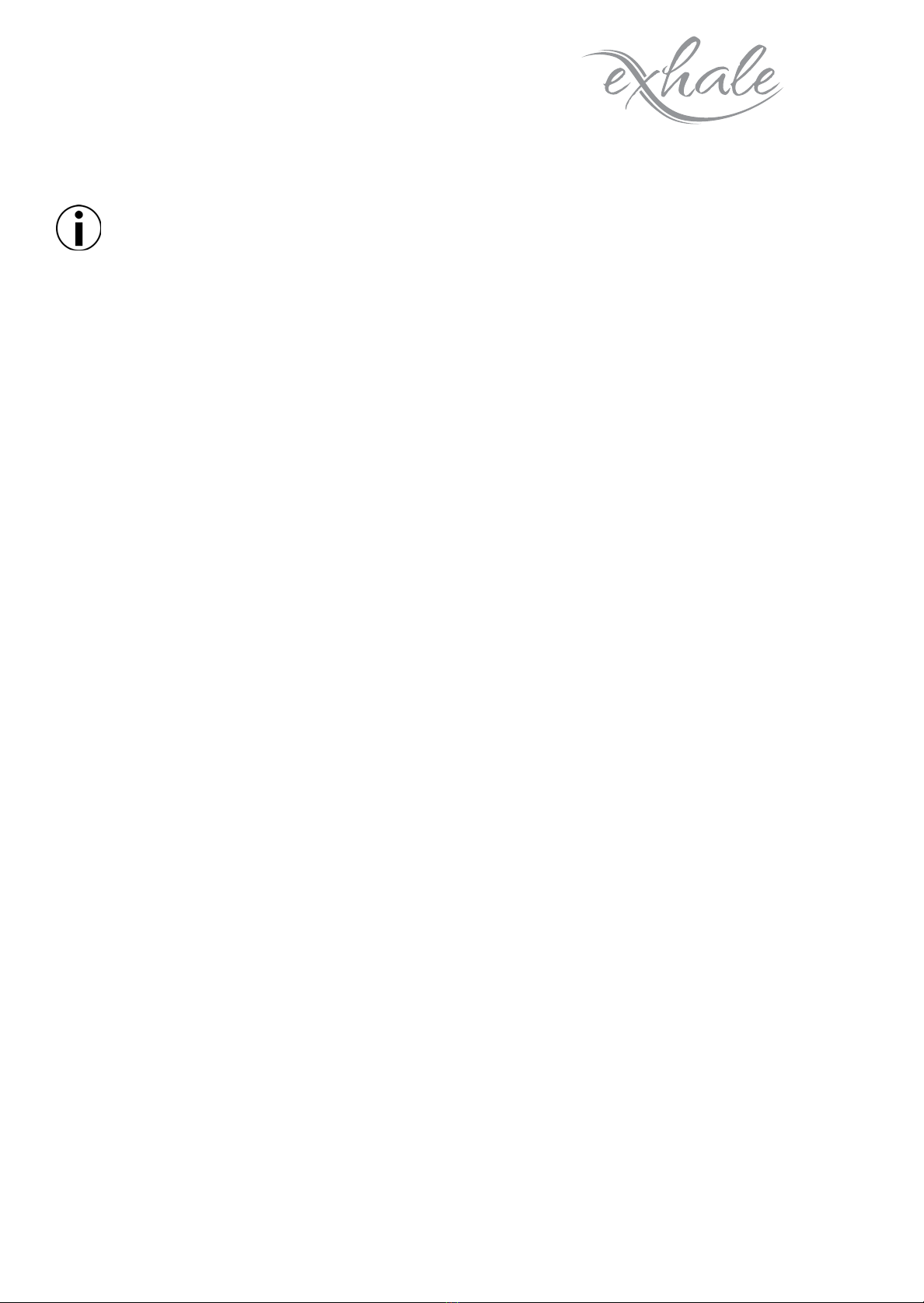
Remote Operation
BUTTON FUNCTIONS
Upper Left SPEED DOWN
Upper Right SPEED UP
Center Left Clockwise (CW)
Counterclockwise (CCW) rotation
Center Right FAN ON/OFF
Lower Left LED DIMMER
Lower Right LED ON/OFF
FANS
Figure 9a.
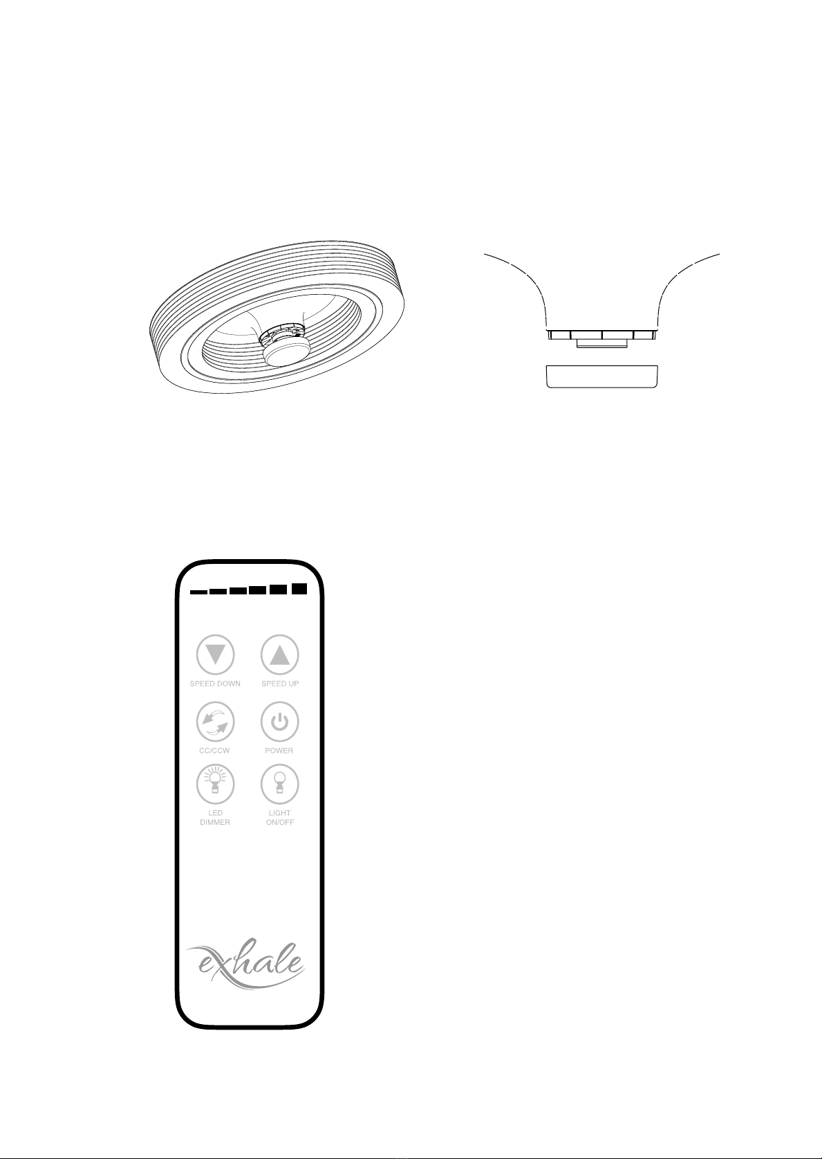
Step 8. Install the Dust Cover (Optional LED Lighting system? Skip this step)
Install the dust cover by sliding it over the center of the disc array as shown in Figure 10. The cover is held on by
friction and should t snugly without using extensive force.
Figure 10.
Protected by one or more of the following US patents: (10,352,325 B2 / D676,543S / D676,952S)
© Exhale Fans, LLC 2018. All rights reserved
FANS
Remote Operation (Cont.)
Each remote is pre-programed to motor when packaged at the factory. However, we have added
instructions below on how to program the remote in the event that it may become necessary.
a. Install the two AAA 1.5 Volt Batteries into the remote transmitter by rst removing the battery cover on the
back cover. Insert the batteries as indicated with the positive + end of the battery aligned with the + sign on
the battery holder.
Operating Functions of the Remote:
The Remote Transmitter has Six Operational Buttons and are depicted (See Figure 9a)
∞To turn the fan ON or OFF select the button labeled POWER.
∞To Increase or Decrease fan Speed select SPEED UP or SPEED DOWN button. The illuminated scale at the
top of the remote will indicate the speed selected, 1 through 6.
∞Please note that the lighted scale on top of the remote will indicate the speed that your fan is operating.
∞To change the direction of rotation, Toggle the CW/CCW button for Clockwise direction or Counterclockwise
direction. The lighted scale will scroll when the CW/CCW button is depressed, right to left for Clockwise,
and Left to right for Counter Clockwise. With your Exhale Fan rotational direction is of personal preference,
performance and temperature are not aected.
∞Turning on the LED light is made by pressing the LED LIGHT ON/OFF button.
∞The LED DIMMER button is used to provide a full-scale dimmer function for your LED. Press and Hold
the dimmer button to select the level of illumination that you desire. While holding this button the level
of illumination will increase to 100% and then decrease to 20%, just release the button at the level of
illumination that you desire.
Remote Programming (Syncing the Remote):
∞Turn the power OFF for at least 10 Seconds, if necessary, turn o the Circuit Breaker that routes power to
your fan.
∞Turn Power to the Fan ON
∞Within 60 seconds of turning the power on, press and hold the LED ON/OFF button for 5 seconds. Do not
touch any other button during this process, doing so will cause this process to fail.
∞Once the Synchronization is completed and detected you will hear an audible “BEEP” which indicates a
successful synchronization.
∞After completing the steps all fan functions will be available.
Please note that if a Power Failure occurs you may have select the CW / CCW direction button since it is not
remembered by the fan.

Protected by one or more of the following US patents: (10,352,325 B2 / D676,543S / D676,952S)
© Exhale Fans, LLC 2018. All rights reserved
Model: EF34
Model: EF34/220-240/50
Voltage: 220-240V 50 Hz. 3 Wire
Power: 65W 0.5A [without LED]
78W 0.6A [with LED]
INSU. Class: F Duty: Continuous
Model: EF34/120/60
Voltage: 120V 60 Hz. 3 Wire
Power: 65W 1.0A [without LED]
78W 1.15A [with LED]
INSU. Class: F Duty: Continuous
The motor is running with 24VDC and it will
not run without the electronic part.
Tech Specs
Dimensions Voltage & Current Rating
Height: 7.5 in / 18.4 cm
Width: 34 in / 86.4 cm
Weight: 25 lbs / 11.4 Kg
Level 1: 33-35 dB
Level 2: 35-37 dB
Level 3: 36-38 dB
Level 4: 37-38 dB
Level 5: 38-41 dB
Level 6: 40-45 dB
(40 dB = Quiet Library)
Energy Usage
Sound dB
Level 1: 4 Watts, 120 RPM
Level 2: 6 Watts, 158 RPM
Level 3: 9 Watts, 198 RPM
Level 4: 16 Watts, 236 RPM
Level 5: 36 Watts, 274 RPM
Level 6: 50 Watts, 285 RPM
Cleaning and Maintenance
WARNING: Make sure the fan is turned o and is not spinning before attempting to clean with either of
the methods listed above.
With any fan, dust will collect on the leading edges where the air passes over.
Using a damp cloth with a mild detergent, wipe the dust from the interior and exterior edges of the discs.
Alternatively, you can use the brush attachment
of your vacuum cleaner to remove dust
collected on the interior and exterior surfaces
of the fan.
We recommend cleaning the fan once a month
to keep dust to a minimum and keep your fan
running at its optimum.
Optional LED Lighting System
Watts: 15 at 100%
Dimmable: 20% to 100%
Lumens: 850-1050 at 100%
Cool White: 5500K
Warm White: 4000K

Protected by one or more of the following US patents: (10,352,325 B2 / D676,543S / D676,952S)
© Exhale Fans, LLC 2018. All rights reserved
FANS
Figure A.
A. Concrete Mounting Hardware
Concrete mounting hardware MUST be used when installing directly to concrete without the use of a
junction box.
Optional Accessories
Parts List
Non Hook
Qty: 3
Hook Anchor
Qty: 1
a. Place the ceiling mount ush onto the ceiling in the
location where the fan will be mounted.
b. Using the mount as a guide, mark the 5 bolt
locations onto the ceiling where the expansion
anchors will be installed.
c. Remove the ceiling mount from the ceiling and check that the 5 locations marked are clear and free from
obstacles. (Note: Use one of the slotted holes in the mount for the anchor with the hook attachment)
d. Using a 10mm drill bit, drill the 4 bolt locations at least 40mm deep into the concrete ceiling.
(Be sure to clean
any remaining dust from the hole when nished.)
e. Run the supply wires through the center of the ceiling mount and secure the mount to the ceiling using the
included 4 expansion anchors.
Installation step 1-3 should be completed prior to installation of the ceiling mount.
Expansion Anchors
f. [Refer to Installation Step 5. Electrical Connections]
g. Secure the fan safety cable to the Hook Expansion Anchor by
placing the open loop of the safety cable over the hook, as seen
in Figure A. The safety cable provided is a backup to the main
suspension / mounting system. One end of the Safety Cable is
anchored to the fan with the opposite end being free to pass
through a “down Rod” thus xing the free end of the cable
securely to the building structure from which the fan is suspended
/ mounted. The safety cable is thus to be attached to the Hook
Expansion Anchor.
h. [Return to Installation Step 6. Mounting the Motor]
Safety Cable
and Hook
Protected by one or more of the following US patents: (10,352,325 B2 / D676,543S / D676,952S)
© Exhale Fans, LLC 2018. All rights reserved
Model: EF34
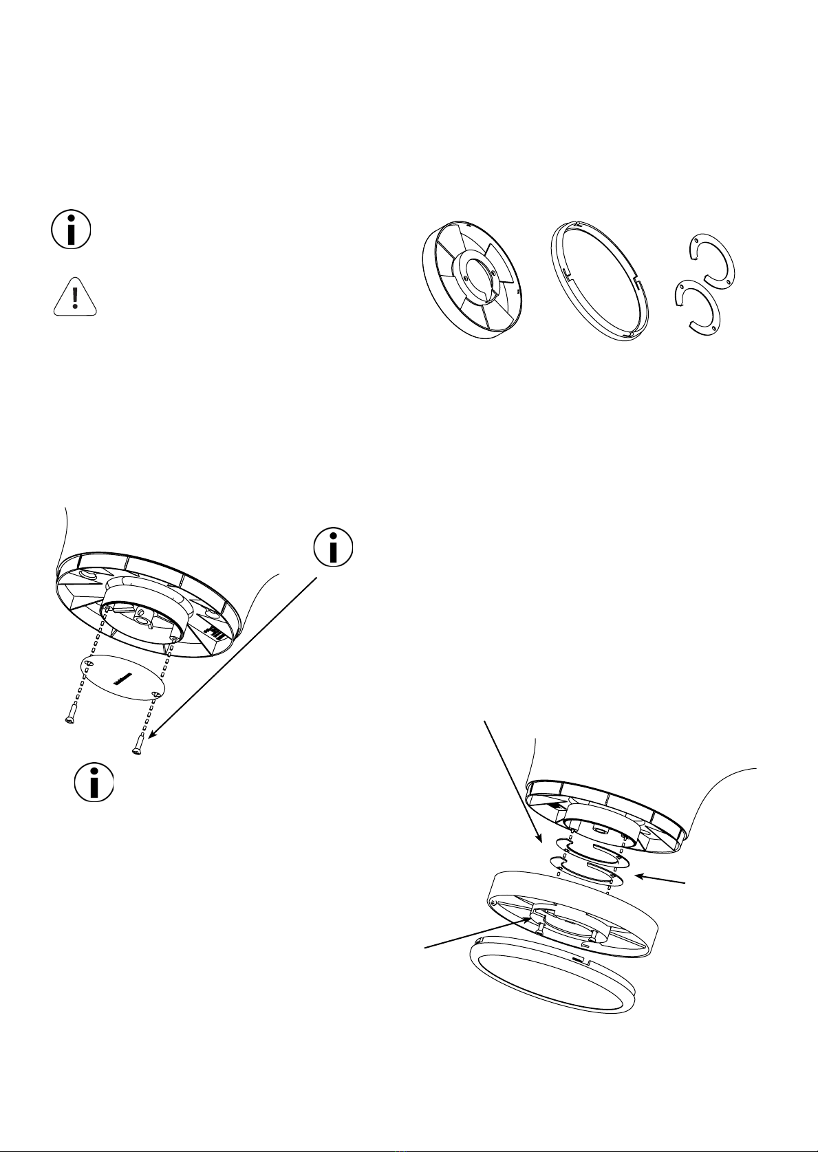
Figure A.
C. EF34 LED Lighting System
Optional Accessories (Continued)
Parts List
a. Turn o all electrical power to the fan while making any electrical connections.
b. Once the disc array has been installed, leveled, and you are happy with its operation, remove the cover from
the housing located directly below the fan, shown in Figure A.
WARNING: To Reduce the Risk of
Electrical Shock, Disconnect the
Electrical Supply Circuit to The Fan
Before Installing EF34 LED Lighting
System.
Main Housing LED Housing Spacers
c. Mount the Main LED Housing to the lower housing using the 2
screws retained from the last step, shown in Figure B.
Note: You may need to use one or more of the included spacers between
the lower housing and Main LED Housing to achieve clearance between
the fan and the LED lighting system to ensure smooth operation
without rubbing.
Retain the 2 mounting screws removed from the lower housing,
they will be used later.
Please take the time to make sure the fan rotates freely
with the Main LED Housing
d. Make the appropriate electrical connection from the LED
Housing to the motor.
Note: The connectors used from the motor to the LED Housing are
Male/Female and can only be installed one way!
Figure B.
Optional
Spacers
e. Take care to tuck the wires into the lower housing using
the Main Housings cutaway as a channel to run the wires.
f. You can now line up the tangs of the Main Housing to the
retainer clips from the LED Housing and gently rotate clockwise to lock them in place.
Only the EF34 (supplied) Lighting System is
authorized for Installation with your fan.
Other manuals for EF34
3
Table of contents
Other Exhale Fans Fan manuals


