Best D49M30SB User manual

Pub Number: 99045685C
Service Manual
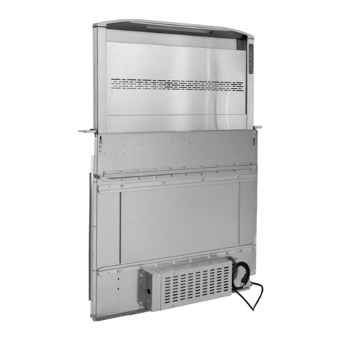
D49M30SB, D49M36SB, D49M48SB Downdraft Ventilator
Cattura™
Downdraft

2Safe servicing practices
To avoid personal injury and/or property damage, it is important that Safe Servicing Practices be
observed. The following are some limited examples of safe practices.
1. DO NOT attempt a product repair if you have any doubts as to your ability to complete it in a safe and
satisfactory manner.
2. Before servicing or moving an appliance, remove the power cord from the electrical outlet, trip the
circuit breaker to the OFF position, or remove the fuse.
3. Never interfere with the proper operation of any safety device.
4. USE ONLY REPLACEMENT PARTS CATALOGED FOR THIS APPLIANCE. SUBSTITUTIONS MAY
DEFEAT COMPLIANCE WITH SAFETY STANDARDS SET FOR HOME APPLIANCES.
5. GROUNDING: The standard color coding for safety ground wires is GREEN, or GREEN WITH
YELLOW STRIPES. Ground leads are not to be used as current-carrying conductors. It is
EXTREMELY important that the service technician re-establish all safety grounds prior to completion
of service. Failure to do so will create a hazard.
6. Prior to returning the product to service, ensure that:
• All electrical connections are correct and secure
• All electrical leads are properly dressed and secured away from sharp edges, high-temperature
components, and moving parts
• All non-insulated electrical terminals, connectors, heaters, etc., are adequately spaced away from
all metal parts and panels
• All safety grounds (both internal and external) are correctly and securely connected
• All panels are properly and securely re-assembled
NOTE
This service manual is intended for use by persons having electrical and mechanical training and a level
of knowledge of these subjects considered acceptable in the appliance repair trade. BEST®cannot be
responsible, or assume any liability, for injury or damage of any kind arising from the use of this manual.
Grounding instructions
FOR PERSONAL SAFETY, THIS APPLIANCE MUST BE PROPERLY GROUNDED.
The power cord on this appliance is equipped with a three-prong (grounding) plug which mates with a
standard three-prong (grounded) receptacle.
If there is a two-prong outlet located where you will install the downdraft, it is your responsibility to have it
replaced with a properly grounded three-prong wall receptacle.
DO NOT, UNDER ANY CIRCUMSTANCES, CUT OR REMOVE THE THIRD (GROUND) PRONG FROM
THE POWER CORD.
A 120-volt, 60 Hz., A.C., 15 amp fused and grounded electrical supply is required (time-delay fuse
or circuit breaker is recommended). It is recommended that a SEPARATE CIRCUIT serving only this
appliance be provided.
DO NOT USE AN EXTENSION CORD WITH THIS APPLIANCE.
BACK
TOC

3
Downdraft components
Top Cap
LED Light Bar
Door Assembly
(behind raised
Chimney)
User Interface
DOWN Button
Door Assembly
Cover (Right) with
UP Button
Airbox Wedge
Assembly (left
and right sides)
Chimney Seal
Actuator
Main
PCB Fuse
Power
Supply
Electrical Box Assembly
(may be mounted to downdraft or
located in a remote location)
Lift Guide Pucks
(30" and 36": set of 4
48": set of 6)
Heat Sentry
Filters (left and
right sides)
Baffles
(left and
right sides)
Lift Guide Cover
Chimney
Chimney Grille
Door
Assembly
Cover (Left)
Angle Brackets
(left and
right sides)
Angle Brackets
(left and
right sides)
Airbox
Adjustment Legs
(left and
right sides)
Airbox Front
Model PF6 Blower
(may be mounted to downdraft
as shown or located in a
remote location; or an exterior
ventillator may be used)
BACK
TOC

4Table of contents
➠
Safe servicing practices 2
➠
Grounding instructions 2
➠
Downdraft components 3
➠
Table of contents 4
Section A – Troubleshooting sequences............................................................................................. 6
➠
Chimney will not rise – UP button will not light 6
➠
Chimney will not rise – UP button lights 8
➠
Chimney will not lower – DOWN button will not light 10
➠
Chimney will not lower – DOWN button lights 12
➠
Unit functioning, but poor cooking plume capture 14
➠
Chimney is raised, but blower does not turn on 15
➠
Unit makes rattling or squeaking noise when Chimney rises or lowers 16
➠
Unit makes rustling or whooshing noise when Chimney rises or lowers 17
➠
Door Assembly not flush with countertop when Chimney is fully lowered 17
➠
Chimney is raised, but LED Light Bar will not turn on 18
➠
Unit does not respond to rangetop heat at any temperature 18
Section B – Wiring test sequences ................................................................................................... 19
1
Test continuity between Door Assembly Cover and Frame 19
1
Test Main PCB 20
1
Test continuity at Triac 22
1
Test Line Filter 23
1
Test 4-pin connector for UP Button wiring 24
1
Test continuity at connector CN10 to make-up air damper 25
1
Jumper terminals to make-up air damper 25
1
Test Power Supply 26
1
Test field wiring to blower 28
1
Test 6-pin connector from Wire Harness to User Interface 30
1
Test User Interface 31
1
Test Actuator circuit continuity 32
1
Test Actuator 33
1
Test continuity at Chimney Obstruction Detection Switches 34
BACK
TOC

5
Section C – Correction steps............................................................................................................. 35
➠
Reseat Chimney Grille 35
➠
Realign or replace Door Assembly or Door Assembly Cover (Left) 36
➠
Repair or replace Door Assembly Cover (Right) with UP Button 37
➠
Replace User Interface 38
➠
Replace LED Light Bar 40
➠
Replace Heat Sentry 42
➠
Replace fuse on Main PCB 43
➠
Replace Main PCB 44
➠
Replace Power Supply 45
➠
Replace Electrical Box 46
➠
Lubricate Airbox Front 47
➠
Replace Chimney Seal 48
➠
Realign Airbox Wedge Assemblies 49
➠
Replace Lift Guide Pucks 50
➠
Replace Actuator 52
➠
Adjust Actuator height 54
➠
Clean or replace Filters 55
➠
Replace Wire Harness 56
➠
Replace downdraft 59
Section D – Specifications ................................................................................................................ 60
➠
Exploded view 60
➠
Service parts 61
➠
Molex and terminal connections 62
➠
Wiring schematic 64
➠
Warranty 66
BACK
TOC

6
SECTION A – TROUBLESHOOTING SEQUENCESSECTION A – TROUBLESHOOTING SEQUENCES
Chimney will not rise – UP button will not light
Continued next page >>
SECTION A – TROUBLESHOOTING SEQUENCES
TesT Response
Press UP button. Does it light? YES
NO
External
Wiring
Check cord plug. Is it fully seated? NO Plug in cord.
YES
Check outlet. Is there voltage? NO Reset circuit breaker.
YES
Cycle power: switch the circuit breaker to the OFF position,
wait 1 minute, switch the circuit breaker to the ON position.
Press UP button. Does button light?
YES
➠
Chimney will not rise – UP
button lights (p.8)
NO
UP Button
Assembly
Is there continuity between Door Assembly Cover and
frame?
1
Test continuity between Door Assembly Cover and
Frame (p.19)
NO
➠
Repair or replace Door Assembly
Cover (Right) with UP Button (p.37)
YES
Inspect O-ring ground connector at bottom of frame. Is it
properly connected?
NO
➠
Repair or replace Door Assembly
Cover (Right) with UP Button (p.37)
YES
Inspect ground connector inside Door Assembly Cover.
Is it fully connected?
NO
➠
Repair or replace Door Assembly
Cover (Right) with UP Button (p.37)
YES
Visually inspect UP button wiring. Are there broken
connectors or breaks in the wiring?
YES
➠
Repair or replace Door Assembly
Cover (Right) with UP Button (p.37)
NO
NOTICE: Unplug the main power cable for the
downdraft and wait 1 full minute (60 seconds) before
disconnecting any Molex connectors. Restore power
after connectors have been disconnected. Failure to
follow these steps may damage the downdraft.
Unplug and test 4-pin connector for UP button wiring,
located at base of unit.
Is there voltage?
1
Test 4-pin connector for UP Button wiring (p.24)
YES
➠
Repair or replace Door Assembly
Cover (Right) with UP Button (p.37)
NO
Power
Supply
1. Locate electrical box.
If necessary, remove rangetop, oven or cooktop
components, or blower assembly, to allow direct
access to Electrical Box.
2. Remove front panel of Electrical Box.
Test AC voltage to power supply:
Is LED lit?
1
Test Power Supply (p.26)
YES NO
Is there line voltage at “L” and “N”
terminals?
1
Test Power Supply (p.26)
YES
➠
Replace Power Supply (p.45)
NO
➠
Replace Electrical Box (p.46)
Is there voltage at “-V” and “+V” terminals?
1
Test Power Supply (p.26)
NO
➠
Replace Power Supply (p.45)
YES
➠
Chimney will not rise – UP
button lights (p.8)
(page 1 of 2)
BACK
TOC

7
SECTION A – TROUBLESHOOTING SEQUENCES
Chimney will not rise – UP button will not light (page 2 of 2)
<< Continued from previous page
TesT Response
Main PCB Test wires and connections at connector CN5 on Main
PCB.
Are all tested voltages correct?
1
Test Main PCB (p.20)
NO
➠
Replace Main PCB (p.44)
YES
User
Interface
Remove User Interface:
NOTICE: Unplug the main power cable for the
downdraft and wait 1 full minute (60 seconds) before
disconnecting any Molex connectors. Restore power
after connectors have been disconnected. Failure to
follow these steps may damage the downdraft.
➠
To see these steps illustrated, refer to “Replace User
Interface” (p.38)
1. Remove Top Cap (3 screws).
2. Disconnect 4-pin Molex connector from UP Button
from back of User Interface.
3. Remove single retaining nut that secures top of User
Interface.
4. Lift out bracket that secures User Interface in place. It
is held in place by friction.
5. Lift out User Interface. Take care that front of User
Interface does not come in contact with retaining bolt.
6. Disconnect 3-pin Molex connector for LED Light Bar
from back of User Interface.
7. Disconnect 6-pin Molex connector from Wire Harness
from back of User Interface.
Test 6-pin Molex connector from Wire Harness:
Are all tested voltages correct?
1
Test 6-pin connector from Wire Harness to User
Interface (p.30)
NO
➠
Replace Wire Harness (p.56)
YES
➠
Replace User Interface (p.38)
AND
➠
Repair or replace Door
Assembly Cover (Right) with UP
Button (p.37)
BACK
TOC

8
SECTION A – TROUBLESHOOTING SEQUENCESSECTION A – TROUBLESHOOTING SEQUENCES
Chimney will not rise – UP button lights
Continued next page >>
(page 1 of 2)
TesT Response
Press UP button. Does it light? NO
YES
Main PCB
1. Locate electrical box.
If necessary, remove rangetop, oven or cooktop
components, or blower assembly, to allow direct
access to Electrical Box.
2. Remove front panel of Electrical Box.
Test wires and connections on Main PCB.
Does voltage at connector CN7 when UP button is
pressed (polarity is marked on Main PCB) = 24 VDC?
1
Test Main PCB (p.20)
NO
➠
Replace Main PCB (p.44)
YES
If Actuator Line Filter is present, test “LOAD” terminals
when UP button is pressed (polarity is marked on Main
PCB).
Does voltage = 24 VDC?
1
Test Line Filter (p.23)
NO
➠
Replace Electrical Box (p.46)
YES
Chimney Is
Obstructed
1. Lift Door Assembly.
2. Visually inspect: is there any interference or
obstruction in Chimney path?
YES
Remove obstruction. Replace any
components that are damaged or
obstructing the Chimney path.
NO
1. Remove Blower Box to access blower air outlet.
If necessary, remove rangetop, oven or cooktop
components to allow direct access to Blower Box.
2. Visually inspect outlet: is there any interference or
obstruction in Chimney path?
YES
NO
1. Remove Airbox Front (14 screws).
2. Visually inspect Chimney path: is there any
interference or obstruction?
YES
NO
➠
Chimney will not rise – UP
button will not light (p.6)
BACK
TOC

9
SECTION A – TROUBLESHOOTING SEQUENCES
Chimney will not rise – UP button lights (page 2 of 2)
<< Continued from previous page
TesT Response
Actuator
Circuit
Continuity
Check actuator circuit continuity.
Is actuator circuit continuity good?
1
Test Actuator circuit continuity (p.32)
YES NO
Chimney
Obstruction
Detection
Switches
Are Chimney Obstruction Detection
Switches closed?
To verify, simultaneously push down on
center of Chimney and press UP button.
Does Chimney rise?
NO
➠
Replace downdraft (p.59)
YES
1. Remove Chimney Front Grill.
2. Remove Lift Guide Cover to access
Chimney Obstruction Detection
Switches.
Test each Chimney Obstruction
Detection Switch:
Is there continuity at the switch while
pressing down on top of Chimney?
1
Test continuity at Chimney Obstruction
Detection Switches
(p.34)
NO
➠
Replace downdraft (p.59)
YES
Actuator Is Actuator operating correctly?
To test Actuator:
1. Disconnect Actuator at Molex connector.
2. Connect two 9-volt batteries in series to achieve
18 VDC (measure with voltmeter to make sure
batteries are connected correctly).
3. Apply 18 VDC to Actuator Molex connector.
4. If Actuator doesn’t rise, reverse polarity and try
again.
5. If Actuator doesn’t rise with either polarity, push
down on center of Chimney while simultaneously
applying 18 VDC (try both polarities).
1
Test Actuator (p.33)
NO
➠
Replace Actuator (p.52)
YES
➠
Replace Wire Harness (p.56)
BACK
TOC

10
SECTION A – TROUBLESHOOTING SEQUENCESSECTION A – TROUBLESHOOTING SEQUENCES
Chimney will not lower – DOWN button will not light
Continued next page >>
(page 1 of 2)
TesT Response
Press DOWN button. Does it light? YES
NO
External
Wiring
Check cord plug. Is it fully seated? NO Plug in cord.
YES
Check outlet. Is there voltage? NO Reset circuit breaker.
YES
Cycle power: switch the circuit breaker to the OFF position,
wait 1 minute, switch the circuit breaker to the ON position.
Press DOWN button. Does button light?
YES
➠
Chimney will not lower –
DOWN button lights (p.12)
NO
Power
Supply
1. Locate electrical box.
If necessary, remove rangetop, oven or cooktop
components, or blower assembly, to allow direct
access to Electrical Box.
2. Remove front panel of Electrical Box.
Test AC voltage to power supply:
Is LED lit?
1
Test Power Supply (p.26)
YES NO
Is there line voltage at “L” and “N”
terminals?
1
Test Power Supply (p.26)
YES
➠
Replace Power Supply (p.45)
NO
➠
Replace Electrical Box (p.46)
Is there voltage at “-V” and “+V” terminals?
1
Test Power Supply (p.26)
NO
➠
Replace Power Supply (p.45)
YES
Main PCB Test wires and connections at connector CN5 on Main
PCB.
Are all tested voltages correct?
1
Test Main PCB (p.20)
NO
➠
Replace Main PCB (p.44)
YES
➠
Chimney will not lower – DOWN
button lights (p.12)
BACK
TOC

11
SECTION A – TROUBLESHOOTING SEQUENCES
Chimney will not lower – DOWN button will not light (page 2 of 2)
<< Continued from previous page
TesT Response
User
Interface
Remove User Interface:
NOTICE: Unplug the main power cable for the
downdraft and wait 1 full minute (60 seconds) before
disconnecting any Molex connectors. Restore power
after connectors have been disconnected. Failure to
follow these steps may damage the downdraft.
➠
To see these steps illustrated, refer to “Replace User
Interface” (p.38)
1. Remove Top Cap (3 screws).
2. Disconnect 4-pin Molex connector from UP Button
from back of User Interface.
3. Remove single retaining nut that secures top of User
Interface.
4. Lift out bracket that secures User Interface in place. It
is held in place by friction.
5. Lift out User Interface. Take care that front of User
Interface does not come in contact with retaining bolt.
6. Disconnect 3-pin Molex connector for LED Light Bar
from back of User Interface.
7. Disconnect 6-pin Molex connector from Wire Harness
from back of User Interface.
Test 6-pin Molex connector from Wire Harness:
Are all tested voltages correct?
1
Test 6-pin connector from Wire Harness to User
Interface (p.30)
NO
➠
Replace Wire Harness (p.56)
YES
➠
Replace User Interface (p.38)
AND
➠
Repair or replace Door
Assembly Cover (Right) with UP
Button (p.37)
BACK
TOC

12
SECTION A – TROUBLESHOOTING SEQUENCESSECTION A – TROUBLESHOOTING SEQUENCES
Chimney will not lower – DOWN button lights
Continued next page >>
(page 1 of 2)
TesT Response
Press DOWN button. Does it light? NO
YES
Main PCB
1. Locate electrical box.
If necessary, remove rangetop, oven or cooktop
components, or blower assembly, to allow direct
access to Electrical Box.
2. Remove front panel of Electrical Box.
Test wires and connections on Main PCB.
Does voltage at connector CN7 when DOWN
button is pressed (polarity is marked on Main
PCB) = 24 VDC?
1
Test Main PCB (p.20)
NO
➠
Replace Main PCB (p.44)
YES
If Actuator Line Filter is present, test “LOAD” terminals
when DOWN button is pressed (polarity is marked on
Main PCB).
Does voltage = 24 VDC?
1
Test Line Filter (p.23)
NO
➠
Replace Electrical Box (p.46)
YES
Chimney Is
Obstructed
1. Lift Door Assembly.
2. Visually inspect: is there any interference or
obstruction in Chimney path?
YES
Remove obstruction. Replace any
components that are damaged or
obstructing the Chimney path.
NO
1. Remove Blower Box to access blower air outlet.
If necessary, remove rangetop, oven or cooktop
components to allow direct access to Blower Box.
2. Visually inspect outlet: is there any interference or
obstruction in Chimney path?
YES
NO
1. Remove Airbox Front (14 screws).
2. Visually inspect Chimney path: is there any
interference or obstruction?
YES
NO
➠
Chimney will not lower – DOWN
button will not light (p.10)
BACK
TOC

13
SECTION A – TROUBLESHOOTING SEQUENCES
Chimney will not lower – DOWN button lights (page 2 of 2)
<< Continued from previous page
TesT Response
Actuator
Circuit
Continuity
Check actuator circuit continuity.
Is actuator circuit continuity good?
1
Test Actuator circuit continuity (p.32)
YES NO
Chimney
Obstruction
Detection
Switches
Are Chimney Obstruction Detection
Switches closed?
To verify, simultaneously push down on
center of Chimney and press DOWN
button. Does Chimney lower?
NO
➠
Replace downdraft (p.59)
YES
1. Remove Chimney Front Grill.
2. Remove Lift Guide Cover to access
Chimney Obstruction Detection
Switches.
Test each Chimney Obstruction
Detection Switch:
Is there continuity at the switch while
pressing down on top of Chimney?
1
Test continuity at Chimney Obstruction
Detection Switches (p.34)
NO
➠
Replace downdraft (p.59)
YES
Actuator Is Actuator operating correctly?
To test Actuator:
1. Disconnect Actuator at Molex connector.
2. Connect two 9-volt batteries in series to achieve
18 VDC (measure with voltmeter to make sure
batteries are connected correctly).
3. Apply 18 VDC to Actuator Molex connector.
4. If Actuator doesn’t rise, reverse polarity and try
again.
5. If Actuator doesn’t rise with either polarity, push
down on center of Chimney while simultaneously
applying 18 VDC (try both polarities).
1
Test Actuator (p.33)
NO
➠
Replace Actuator (p.52)
YES
➠
Replace Wire Harness (p.56)
BACK
TOC

14
SECTION A – TROUBLESHOOTING SEQUENCESSECTION A – TROUBLESHOOTING SEQUENCES
Unit functioning, but poor cooking plume capture
TesT Response
Filters
Dirty or
Damaged
1. Press UP button to raise Chimney.
2. Remove Chimney Grille.
Inspect lters.
Is there excessive grease accumulation?
YES
➠
Clean or replace Filters (p.55)
NO
External
Ducting
Issues
Access ductwork.
Inspect ductwork: are there leaks? YES Retape ductwork.
NO
Check that ductwork is properly congured:
Is the size or area of the ductwork never smaller
than the size that originates at the hood?
Is duct length less than 50 linear feet?
Is there minimal use of elbows and transitions
(4 or less)?
Are 90° elbows separated with at least 2 feet
of straight ductwork?
Are transitions placed at least 1 foot from the
hood outlet or remote blower inlet?
NO Recongure ductwork.
YES
Inspect roof or wall cap:
Is it free of obstruction or damage?
Does damper ap operate correctly?
Is vent screen clean?
NO Repair or replace.
YES
Problem
with
Make-
Up Air
Damper
Locate electrical box.
If necessary, remove rangetop, oven or cooktop
components, or blower assembly, to allow direct access
to Electrical Box.
Check make-up air damper terminal screws.
Are there wires connected to them?
NO Residence may require make-up air
damper.
YES
Jumper make-up air damper terminal screws.
Does damper open?
1
Jumper terminals to make-up air damper (p.25)
NO Troubleshoot make-up air damper.
YES
Remove jumper and turn blower on.
Does damper open?
NO
➠
Replace Main PCB (p.44)
YES
Are there obstructions in make-up air damper? YES Remove obstructions.
BACK
TOC

15
SECTION A – TROUBLESHOOTING SEQUENCES
Chimney is raised, but blower does not turn on
TesT Response
Press LED light button. Does LED Light Bar illuminate?
LED light button only works when Chimney is fully raised.
NO
YES
User
Interface
Press fan speed button on User Interface.
Does fan speed indicator change?
NO
➠
Replace User Interface (p.38)
YES
Field
Wiring
Issues
1. Locate electrical box.
If necessary, remove rangetop, oven or cooktop
components, or blower assembly, to allow direct
access to Electrical Box.
2. Remove front panel for eld wiring compartment
(smaller panel on left side).
3. Set fan speed to high, then cycle through fan speeds.
Test connection to blower at CN1-CN2:
Are voltages correct at all fan speeds?
1
Test field wiring to blower (p.28)
NO
➠
Replace Electrical Box (p.46)
YES Troubleshoot blower.
➠
Go to Chimney will not rise –
UP button lights (p.8)
BACK
TOC

16
SECTION A – TROUBLESHOOTING SEQUENCESSECTION A – TROUBLESHOOTING SEQUENCES
Unit makes rattling or squeaking noise when Chimney rises or
lowers
TesT Response
Chimney
Grille Not
Properly
Seated
Press UP button to raise Chimney.
Inspect back of Chimney Grille.
Are ears on either side of Lift Guide Cover seated
rmly in retaining tabs at back of Chimney Grille?
NO
➠
Reseat Chimney Grille (p.35)
YES
Chimney
Damaged
Inspect Chimney. Are there visible signs of damage? YES
➠
Replace downdraft (p.59)
NO
Airbox
Wedge
Assemblies
Are
Misaligned
Grab both sides of Chimney and attempt to twist it or
move it laterally within the frame.
Are Airbox Wedge Assemblies too loose or too tight?
-If the Chimney shifts or rattles when twisted, the
Airbox Wedge Assemblies are too loose.
-If the Chimney feels as if it is jammed in place,
the Airbox Wedge Assemblies are too tight.
YES
➠
Realign Airbox Wedge
Assemblies (p.49)
NO
Airbox
Front
Requires
Lubrication
1. Access Airbox Front.
If necessary, remove rangetop, oven or cooktop
components, blower assembly, or Electrical Box, to
allow full access to and adequate space to remove
Airbox Front.
2. Remove Airbox Front (14 screws).
Inspect inside panel of Airbox Front.
Is it lubricated along entire length that Chimney Seal
travels when Chimney is raised or lowered?
NO
➠
Lubricate Airbox Front (p.47)
YES
Chimney
Seal
Damaged
Inspect Chimney Seal. Is there visible wear or damage? YES
➠
Replace Chimney Seal (p.48)
NO
Lift Guide
Pucks
Damaged
1. Press UP button to raise Chimney.
2. Remove screws (2 each) from four Lift Guide Pucks.
Pucks are located at bottom center of Chimney, on
either side of Actuator.
NOTE: 48
"
unit has additional Lift Guide Pucks
in tracks located midway between Actuator and
Chimney columns.
3. Slide Lift Guide Pucks down and out of their
respective tracks.
Visually inspect Lift Guide Pucks. Do any of them show
excessive wear or damage?
YES
➠
Replace Lift Guide Pucks (p.50)
BACK
TOC

17
SECTION A – TROUBLESHOOTING SEQUENCES
Unit makes rustling or whooshing noise when Chimney rises or
lowers
Door Assembly not ush with countertop when Chimney is fully
lowered
TesT Response
Door
Obstructed
Lift Door Assembly and visually inspect.
Are there visible obstructions?
YES Remove obstructions.
NO
Door
Assembly
Misaligned
or
Damaged
Press DOWN button to lower Chimney.
Inspect Door Assembly.
Is there visible damage or misalignment? YES
➠
Realign or replace Door
Assembly or Door Assembly
Cover (Left) (p.36)
AND/OR
➠
Repair or replace Door
Assembly Cover (Right) with UP
Button (p.37)
Inspect Door Assembly Cover (Left).
Is there visible damage or misalignment? YES
Inspect Door Assembly Cover (Right) with UP button.
Is there visible damage or misalignment? YES
Inspect Door Assembly hinges on both sides.
Is there visible damage or misalignment? YES
NO
Actuator
Height
Incorrect
Lift Door Assembly and note position of Chimney when
fully lowered.
Does the Door Assembly rest directly on Chimney at
an incorrect height?
YES
➠
Adjust Actuator height (p.54)
TesT Response
Packing
Material
Left in Unit
During
Installation
1. Press UP button to raise Chimney.
2. Remove Chimney Grille.
Inspect inside of Chimney: is any plastic or cardboard
packing material visible?
YES Remove material.
NO
External
Ducting
Issues
Access and inspect ductwork. Are there visible leaks? YES Retape ductwork.
NO
Check that ductwork is properly congured:
Is the size or area of the ductwork never smaller
than the size that originates at the hood?
Is duct length less than 50 linear feet?
Is there minimal use of elbows and transitions
(4 or less)?
Are 90° elbows separated with at least 2 feet
of straight ductwork?
Are transitions placed at least 1 foot from the
hood outlet or remote blower inlet?
YES NOTE: When using a remote
exterior blower, including one 90°
elbow will reduce blower noise.
NO Recongure ductwork.
BACK
TOC

18
SECTION A – TROUBLESHOOTING SEQUENCESSECTION A – TROUBLESHOOTING SEQUENCES
Chimney is raised, but LED Light Bar will not turn on
Unit does not respond to rangetop heat at any temperature
TesT Response
Heat
Sentry
Defective
1. Press UP button to raise Chimney.
2. Remove Chimney Grille.
3. Remove Lift Guide Cover.
Apply heat directly to Heat Sentry using a hair dryer set
on high until Heat Sentry temperature reaches 158°F
(70°C).
Does blower activate at high speed, then return
to original setting (including OFF) once heat
is removed and a suitable latency period has
passed?
NO
➠
Replace Heat Sentry (p.42)
TesT Response
Press fan speed button. Does fan speed change?
Fan speed button only works when Chimney is fully raised.
NO
YES
LED Light
Bar
Remove User Interface:
NOTICE: Unplug the main power cable for the
downdraft and wait 1 full minute (60 seconds) before
disconnecting any Molex connectors. Restore power
after connectors have been disconnected. Failure to
follow these steps may damage the downdraft.
1. Remove Top Cap (3 screws).
2. Disconnect 4-pin Molex connector from UP Button
from back of User Interface.
3. Remove single retaining nut that secures top of User
Interface.
4. Lift out bracket that secures User Interface in place. It
is held in place by friction.
5. Lift out User Interface. Take care that front of User
Interface does not come in contact with retaining bolt.
6. Disconnect 3-pin Molex connector for LED Light Bar
from back of User Interface.
7. Disconnect 6-pin Molex connector from Wire Harness
from back of User Interface and thread connector and
wires through User Interface port in Chimney column.
8. Reconnect 6-pin Molex connector and User Interface.
Test voltage between pins 1 and 3 in User Interface
connection to LED Light Bar.
Is voltage correct?
1
Test User Interface (p.31)
YES
➠
Replace LED Light Bar (p.40)
NO
➠
Replace User Interface (p.38)
➠
Go to Chimney will not rise –
UP button lights (p.8)
BACK
TOC

19
SECTION B – WIRING TEST SEQUENCES
Test continuity between Door Assembly Cover and Frame
0.7
<1Ω acceptable
SECTION B – WIRING TEST SEQUENCES
BACK
TOC

20
SECTION B – WIRING TEST SEQUENCES
Test Main PCB
NOTICE
Follow these steps before disconnecting
or reconnecting ANY wiring in the
downdraft. Failure to do so may damage
the downdraft.
1. Unplug main power
cable from wall socket or
external power supply.
2. Wait 1 full minute
(60 seconds).
3. Disconnect or reconnect wiring as
directed by the correction steps.
4. Plug in main power cable to restore
power to downdraft.
NOTICE
Terminal connections inside Molex
connectors are easily bent or broken. Do
not force probes when testing connectors.
VAC
120.0
Recorded values ±10%
are acceptable
24.00 VDC
CN3
CN1
(page 1 of 2)
Continued next page >>
BACK
TOC
Other manuals for D49M30SB
3
This manual suits for next models
2
Table of contents
Other Best Fan manuals