Exhale Fans EF34 User manual

Owner's Guide & Installation Manual
MODEL EF34
FANS
GB
V5.1
Please read this manual before installing
and using your Exhale fan to avoid injury and product damage.
We recommend to ask for a qualied electrician
to install the fan for you.
Keep this manual in a safe location for future reference.
The manual can also be downloaded from our Website.
Exhale Europe/Freerise – La Noria 14 – 806 route d’Antibes, 06410 BIOT, France
www.exhale-europe.com – contact@exhale-europe.com
Protected by one or more of the following US patents: (D652.133S, 29/341,859, 29/391,310, 13/662,910)
© Exhale Fans, LLC 2018. All rights reserved
Model: EF34 2
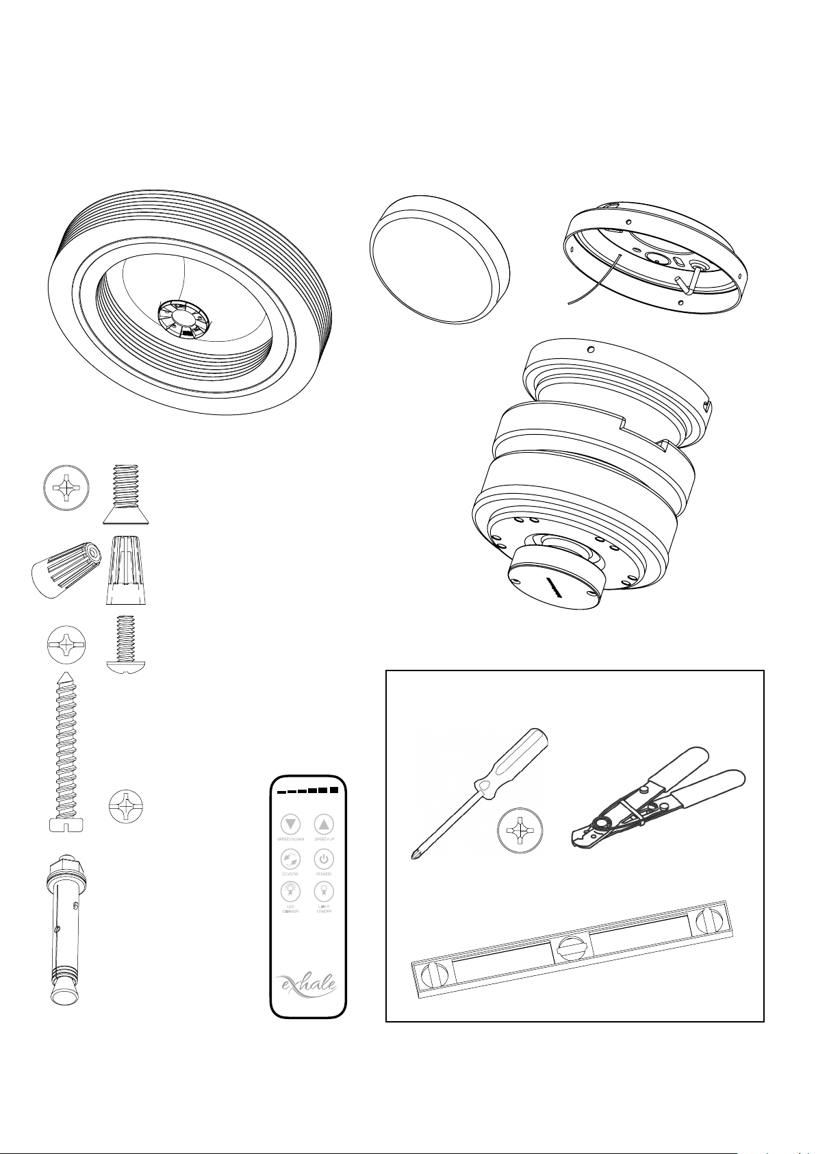
Parts List
Tools Required
Screw Driver
Level
(Magnetic if available)
Wire Strippers
1
1
2
2
3
3
4
4
A A
B B
C C
D D
SHEET 1 OF 1
DRAWN
CHECKED
QA
MFG
APPROVED
nhiner 5/17/2013
DWG NO
TITLE
SIZE
C
SCALE
REV
Exhale Fan (Prebuilt)
LED Light
DC Motor
Flat countersunk head screw,
quantity 5, for xing the fan on the
underside of the motor
Ceiling Mount
Screw at rounded heads, golden
color, for mounting the motor on
the ceiling mount quantity 4
Wire Nuts
Quantity: 3
Various screws for xing the support to the
ceiling only on wooden ceiling
Quantity: 4
Wireless Remote
FANS
The engine must not
be placed directly
on an unreinforced
Plasterboard (BA 13)
ceiling. Ceiling xing
must be able to
support at least 25
kg (fan is 11.3 kilos)
Expanding golden
metal anchors for
concrete laying X4

Protected by one or more of the following US patents: (D652.133S, 29/341,859, 29/391,310, 13/662,910)
© Exhale Fans, LLC 2018. All rights reserved
3
FANS
Installation
Step 1. Determine the location
The preferred location for the EF34 is in the center of the room, this position will provide the best
performance of the fan.
If you intend to place multiple fans in the same room you should divide the room into equal sections
and place the fans in the center of each section. In both instances of one or multiple fans, the above
recommendations will provide air movement coverage to all corners of the space.
Step 2. Remove contents from the package
The 2-part protective foam covers the entire fan. Lift the top cover of the housing. Located at each corner
of the protective foam, you will nd all the parts located in storage locations.
Do not remove the body of the Exhale™ Fan at this time; that will come later in the installation.
Step 3. Turn o all electrical power
Locate your electrical panel or fuse box and turn o the power to the room where you are installing the
fan.
WARNING: Turn o all electrical power prior
to making any electrical connections. Failure
to do so could result in electrical shock.
If you are unsure how to disconnect the electric
power, please consult a licensed electrician for
assistance. Table of electric circuit
breakers in the house.
Protected by one or more of the following US patents: (D652.133S, 29/341,859, 29/391,310, 13/662,910)
© Exhale Fans, LLC 2018. All rights reserved
Model: EF34 4
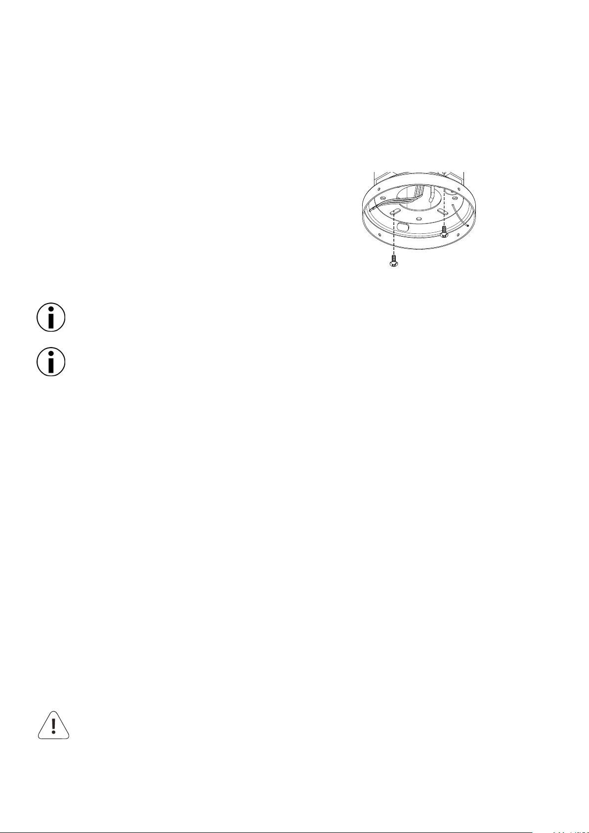
Step 4. Ceiling Mount
a. Pass the electrical wires from the ceiling through the
ceiling mount center hole as shown in Figure 1.
b. x the support to the ceiling with suitable plugs
c. Using a level, make sure the mount is plumb and level to
the oor, adjust if necessary.
d. (We oer a solution for inclined ceilings (up
to 45 degrees, contact us or check our online
shop)
Figure 1.
Step 5. Electrical Connections
a. Connect the fan neutral wire (black)to the black household supply wire as shown in Figure 4.
b. Connect the phase supply (red) to the red household supply as shown in Figure 4.
c. Connect the Ground fan wire (Green & yellow) to the ground household supply as shown in gure 4.
Red = Phase. Black = Neutral. Green/yellow = neutral
d. After connecting all the wiring, spread them apart so that the Green and White wires are located on
one side of the electrical box and the Black on the other.
e. Turn the wire nuts upward and push the wires neatly into the electrical box so they are out of the way.
f. Secure the fan safety cable hook through the slot on the ceiling mount that is opposite of the ceiling
mount hook.
WARNING: To reduce the risk of electrical shock,
DO NOT use a wall-mounted speed control with this fan.
Start by hanging the motor from the ceiling mount hook
as shown in Figure 3.
Running the Exhale out of level can cause it to become unstable or wobble.
Installation to concrete ceilings requires optional mounting hardware. (See Optional Accessories A)

Protected by one or more of the following US patents: (D652.133S, 29/341,859, 29/391,310, 13/662,910)
© Exhale Fans, LLC 2018. All rights reserved
5
FANS
Figure 4.
Step 6. Mounting the Motor
Pre-install 2 of the included #10-24 screws half-way into the
ceiling mount on either side.
Install the motor onto the ceiling mount by sliding the
preinstalled bottom mount over the ceiling mount as
shown in Figure 5.
Using a clockwise twisting motion, the motor will
temporarily lock into the ceiling mount while you install the
remaining 2 #10-24 screws and tighten all connections.
Be sure an align the two twist lock channels with
the 2 pre-installed screws added rst.
Figure 5.
Use the wire connecting nuts supplied with your fan.
Secure the connectors with electrical tape.
Make sure there are no loose strands or connections.
Black
White
Black
White
Ground
Protected by one or more of the following US patents: (D652.133S, 29/341,859, 29/391,310, 13/662,910)
© Exhale Fans, LLC 2018. All rights reserved
Model: EF34 6
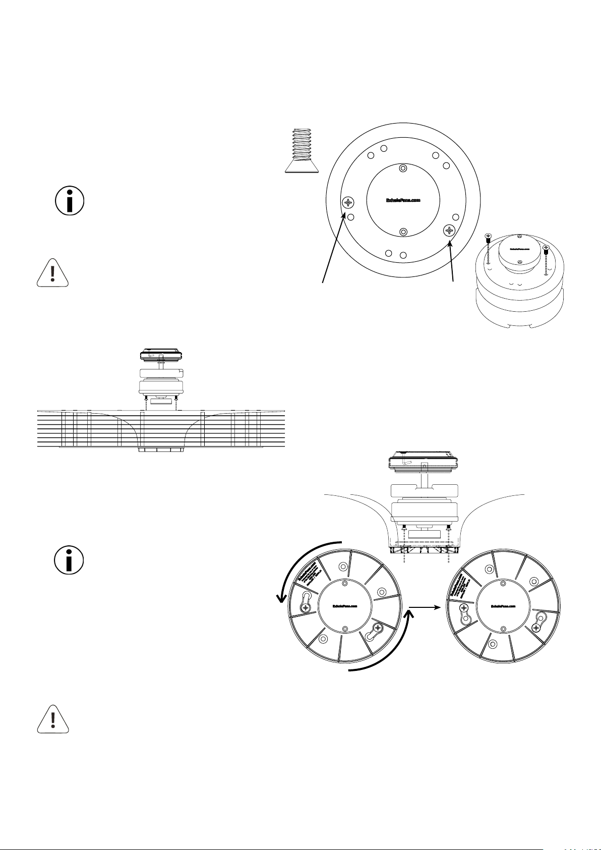
Step 7. Hanging the Disc Array
a. Using only (2) of the included 1/4-20 at
head motor mount screws, install them (2)
full rotations as shown in Figure 7.
Note: These screws will be
tightened completely in a later step.
Figure 7.
Install (2) motor mount screws
2 full turns into the motor. The
locations for the screws are
marked with a small white mark.
WARNING: Not installing the screws
a full (2) rotations could result in
them backing out and causing the disc
array to fall prior to installing the remaining
screws.
b. Install the disc array onto the motor by
aligning the (2) screws installed earlier to
the 'Key Holes' in the disc array as shown in
Figure 9.
Figure 8.
c. Rotate the entire disc array counter
clockwise to lock the screws into the
disc array as shown in Figure 9.
Note: The disc array should be
free hanging from the (2)
mounting screws.
d. Install the remaining (3) screws into the
disc array tightening all (5) using an
alternating pattern to ensure an even
pressure is put on all screws.
Figure 9.
WARNING: Not tightening the motor mounting screws properly could result in a weak
connection of disc array to the motor and cause the fan to become unstable or fall.
Protected by one or more of the following US patents: (D652.133S, 29/341,859, 29/391,310, 13/662,910)
© Exhale Fans, LLC 2018. All rights reserved
7
FANS
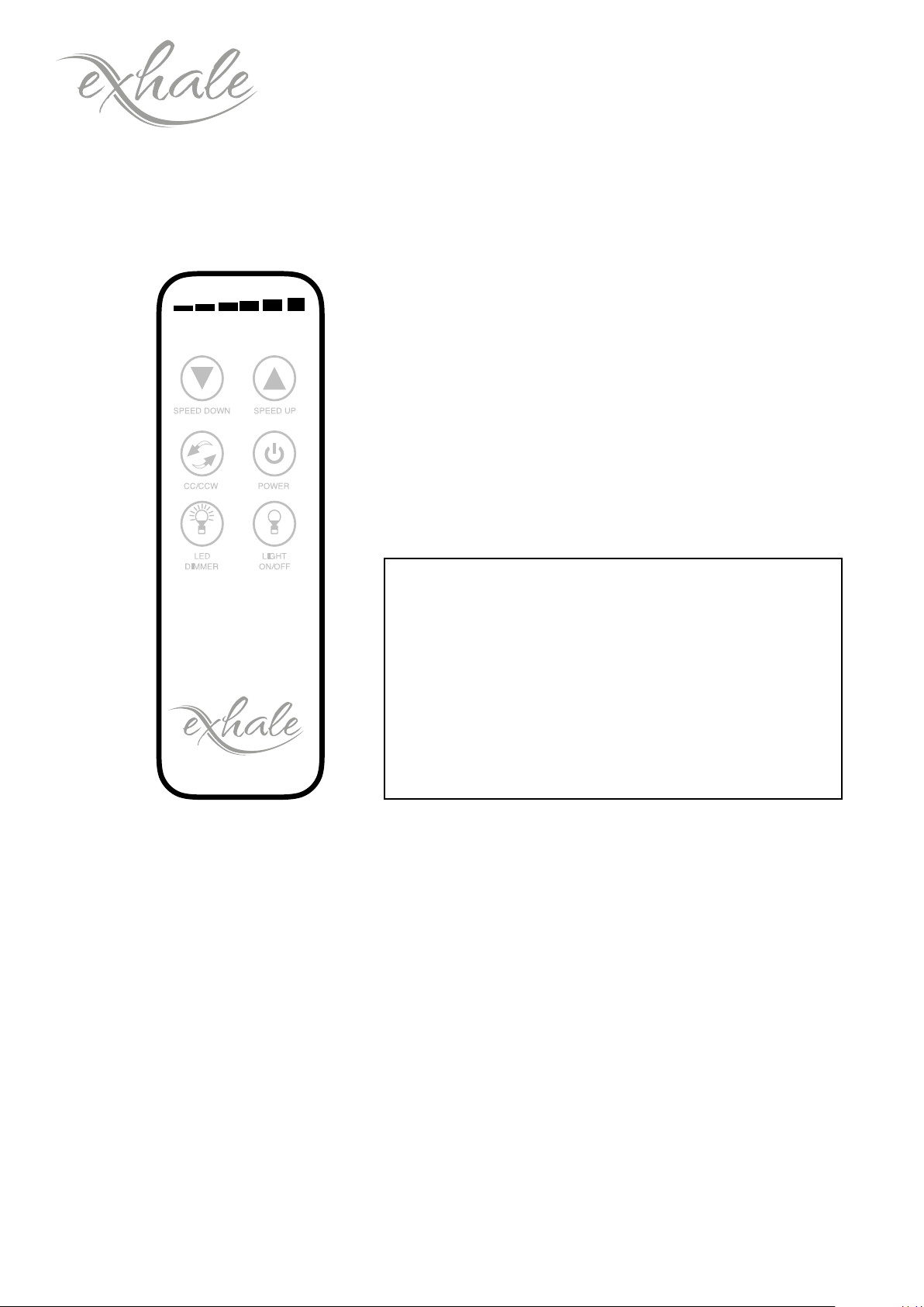
Remote Operation
BUTTON FUNCTIONS
Upper Left SPEED DOWN
Upper Right SPEED UP
Center Left ClockWise (CW)
CounterClockWise (CCW) rotation
Center Right FAN ON/OFF
Lower Left LED DIMMER
Lower Right LED ON/OFF
FANS
Figure 9a.
If you are unsure how to
disconnect the electric power, or
feel that you do not have enough
electrical knowledge, please
consult a licensed electrician for
assistance.

Protected by one or more of the following US patents: (D652.133S, 29/341,859, 29/391,310, 13/662,910)
© Exhale Fans, LLC 2018. All rights reserved
Model: EF34 8
Remote Operation (Cont.)
Each remote is pre-programed to motor when packaged at the factory. However, we have added
instructions below on how to program the remote in the event that it may become necessary.
a. Install the two AAA 1.5 Volt Batteries into the remote transmitter by rst removing the battery cover on the
back cover. Insert the batteries as indicated with the positive + end of the battery aligned with the + sign on
the battery holder.
Operating Functions of the Remote:
The Remote Transmitter has Six Operational Buttons and are depicted (See Figure 9a)
∞To turn the fan ON or OFF select the button labeled POWER.
∞To Increase or Decrease fan Speed select SPEED UP or SPEED DOWN button. The illuminated scale at the
top of the remote will indicate the speed selected, 1 through 6.
∞Please note that the lighted scale on top of the remote will indicate the speed that your fan is operating.
∞To change the direction of rotation, Toggle the CW/CCW button for ClockWise direction or
CounterClockWise direction. The lighted scale will scroll when the CW/CCW button is depressed, right to
left for Clockwise, and Left to right for Counter Clockwise. With your Exhale Fan rotational direction is of
personal preference, performance and temperature are not aected.
∞Turning on the LED light is made by pressing the LED LIGHT ON/OFF button.
∞The LED DIMMER button is used to provide a full-scale dimmer function for your LED. Press and Hold
the dimmer button to select the level of illumination that you desire. While holding this button the level
of illumination will increase to 100% and then decrease to 20%, just release the button at the level of
illumination that you desire.
Remote Programming (Syncing the Remote):
∞Turn the power OFF for at least 10 Seconds, if necessary, turn o the Circuit Breaker that routes power to
your fan.
∞Turn Power to the Fan ON
∞Within 60 seconds of turning the power on, press and hold the LED ON/OFF button for 5 seconds. Do not
touch any other button during this process, doing so will cause this process to fail.
∞Once the Synchronization is completed and detected you will hear an audible “BEEP” which indicates a
successful synchronization.
∞After completing the steps all fan functions will be available.
Please note that if a Power Failure occurs you may have select the CW / CCW direction button since it is not
remembered by the fan.
Protected by one or more of the following US patents: (D652.133S, 29/341,859, 29/391,310, 13/662,910)
© Exhale Fans, LLC 2018. All rights reserved
9
FANS
AC Input 100 – 265 Volts,
50 or 60 Hz.
Tech Specs
Dimensions Voltage Options
Height: 7.5 in / 18.4 cm
Width: 34 in / 86.4 cm
Weight: 25 lbs / 11.4 Kg
Level 1: 33-35 dB
Level 2: 35-37 dB
Level 3: 36-38 dB
Level 4: 37-38 dB
Level 5: 38-41 dB
Level 6: 40-45 dB
Energy Usage Sound dB
Level 1: 4 Watts, 120 RPM
Level 2: 6 Watts, 158 RPM
Level 3: 9 Watts, 198 RPM
Level 4: 16 Watts, 236 RPM
Level 5: 36 Watts, 274 RPM
Level 6: 50 Watts, 312 RPM
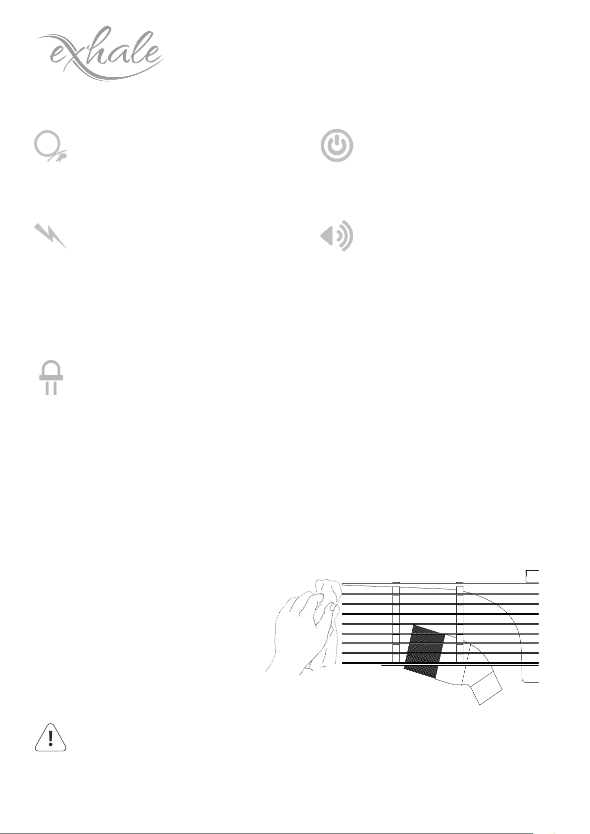
Cleaning and Maintenance
WARNING: Make sure the fan is turned o and is not spinning before attempting to clean with
either of the methods listed above.
With any fan, dust will collect on the leading edges where the air passes over.
Using a damp cloth with a mild detergent, wipe the dust from the interior and exterior edges of the discs.
Alternatively, you can use the brush attachment of your vacuum cleaner to remove dust collected on the
interior and exterior surfaces of the fan.
We recommend cleaning the fan once a
month to keep dust to a minimum and
keep your fan running at its optimum.
Optional LED Lighting System
Watts: 15 at 100%
Dimmable: 20% to 100%
Lumens: 850-1050 at 100%
Cool White: 5500K
Warm White: 4000K

Protected by one or more of the following US patents: (D652.133S, 29/341,859, 29/391,310, 13/662,910)
© Exhale Fans, LLC 2018. All rights reserved
Model: EF34 10
Figure A.
A. Concrete Mounting Hardware
Concrete mounting hardware MUST be used when installing directly to concrete without the use of
a junction box.
Optional Accessories
Parts List Qty: 4
a. Place the ceiling mount ush onto the ceiling in the
location where the fan will be mounted.
b. Using the mount as a guide, mark the 5 bolt locations
onto the ceiling where the expansion anchors will be
installed.
c. Remove the ceiling mount from the ceiling and check that the 5 locations marked are clear and
free from obstacles. (Note: Use one of the slotted holes in the mount for the anchor with the hook
attachment)
d. Using a 10mm drill bit, drill the 4 bolt locations at least 40mm deep into the concrete ceiling.
(Be sure
to clean any remaining dust from the hole when nished.)
Installation step 1-3 should be completed prior to installation of the ceiling mount.
Expansion Anchors
e. Run the supply wires through the center of the ceiling mount
and secure the mount to the ceiling using the included 4
expansion anchors that do not include the support hook.
f. [Refer to Installation Step 5. Electrical Connections]
g. Secure the fan safety cable from the motor to the expansion
bolt with support hook by sliding the open loop of the safety
cable over the hook and sliding the loop collar until it is tight
around the shaft of the hook as seen in Figure a.
h. [Return to Installation Step 6. Mounting the Motor]
Blue
Brown
Green
B. Electrical Terminal Block
If your motor has a pre-installed terminal block on the lower motor
bracket, your local code requires its use. Please make all electrical
connections within the terminal block according to your local
standards and regulations.

Protected by one or more of the following US patents: (D652.133S, 29/341,859, 29/391,310, 13/662,910)
© Exhale Fans, LLC 2018. All rights reserved
11
FANS
Figure A.
C. LED Lighting System
Optional Accessories (Continued)
Parts List
a. Turn o all electrical power to the fan while making any electrical connections.
b. Once the disc array has been installed, leveled, and you are happy with its operation, remove the
cover from the housing located directly below the fan, shown in Figure A.
WARNING: Turn o all electrical
power prior to making any
electrical connections. Failure to do so
could result in electrical shock, personal
injury, or death.
Main Housing LED Housing Spacers
c. Mount the Main LED Housing to the lower housing using the 2
screws retained from the last step, shown in Figure B.
Note: You may need to use one or more of the included spacers
between the lower housing and Main LED Housing to achieve
clearance between the fan and the LED lighting system to ensure
smooth operation without rubbing.
Retain the 2 mounting screws removed from the lower
housing, they will be used later.
Please take the time to make sure the fan rotates
freely with the Main LED Housing
d. Make the appropriate electrical connection from the LED
Housing to the motor.
Note: The connectors used from the motor to the LED Housing
are Male/Female and can only be installed one way!
Figure B.
Optional
Spacers
e. Take care to tuck the wires into the lower housing
using the Main Housings cutaway as a channel to
run the wires.
f. You can now line up the tangs of the Main Housing to the
retainer clips from the LED Housing and gently rotate clockwise to lock them in place.
Protected by one or more of the following US patents: (D652.133S, 29/341,859, 29/391,310, 13/662,910)
© Exhale Fans, LLC 2018. All rights reserved
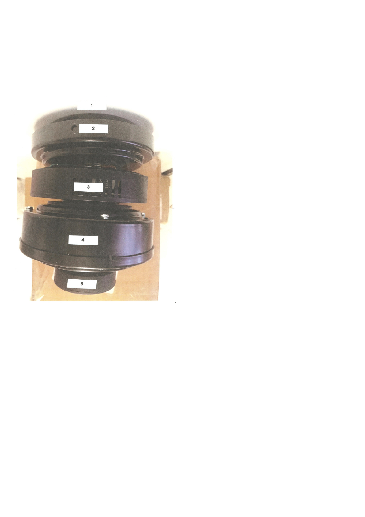
Model: EF34 12
Level 1
Black metal mounting bracket with holes for
ceiling mounting.
On the circumference four threaded holes to
receive the 4 golden curved xing screws for
connection with the top of the engine and this
support.
A hook for engine support the time of the
electrical connection with the ceiling wires.
Level 2
Metal cup with 2 round holes and 2 oblong holes
for xing with the screws above.
First fasten the screws 1 and 2 in the oor bracket
1 and then insert the oor 2, turn it to lock the
motor and x and lock the screws 3 and 4. Finish
by blocking screws 1 and 2.
We see out of the central axis locked by a pin the
3 wires and the cable of xation.
Level 3
Protective plastic box Printed Circuit Board (PCB) motor control and lighting by remote control.
This case has a exible mounting on the central axis of the engine and slightly moved slightly.
Level 4
The engine itself, do not open.
Level 5
Black plastic case for LED lighting support (warm W or C cold light) or replacement cover.
Lexicon
Other manuals for EF34
3
Table of contents
Other Exhale Fans Fan manuals


Popular Fan manuals by other brands


Hurricane
Hurricane Afterburner Instruction guide

Craftmade
Craftmade Frontier FT52 Specifications

Fanimation
Fanimation SLINGER LP8147SLBN manual

EDM
EDM 33915 instruction manual

DuraVent
DuraVent duraplus htc installation instructions

Fanimation
Fanimation FARGO FP3320 Series Set-up and maintenance instructions sheet

International comfort products
International comfort products FEM4X installation instructions

TPI Corporation
TPI Corporation CACU24-P owner's manual

Faro Barcelona
Faro Barcelona ALO 33718 installation guide

Sealey
Sealey HVD16C quick start guide

ALPATEC
ALPATEC TF 78 manual

Komfovent
Komfovent KOMPAKT REGO Series Installation and operation manual