Exhale Fans EF34 Instruction manual
Owner’s Guide
&
Installation manual
Please read this manual before installing
and using your Exhale fan to avoid injury and
product damage.
We recommend to ask for a qualified electrician to
install the fan for you.
Keep this manual in a safe location for future
reference. The manual can also be downloaded from
our Website.
Exhale Europe –806 route Antibes 06410 BIOT France
www.exhale-europe.com -+33 4 92 38 96 50 –contact@exhale-europe.com
GB
V6
1
MODEL EF34
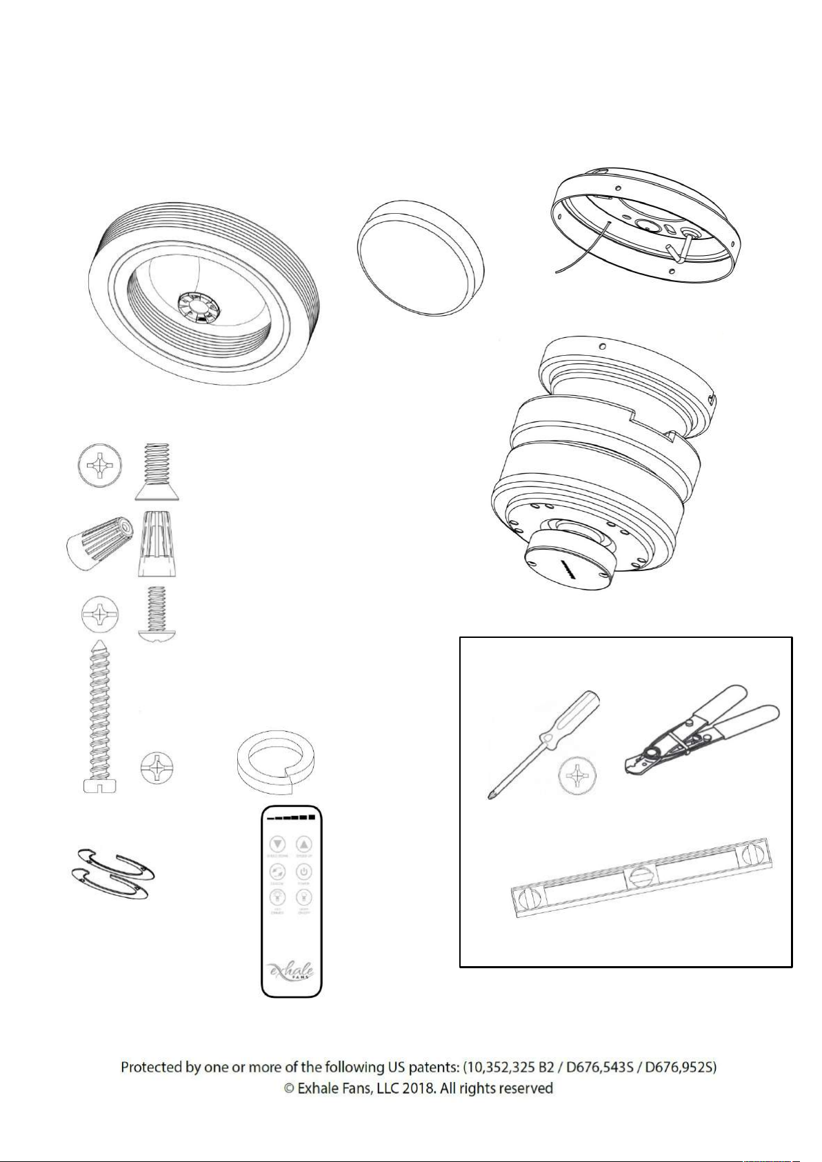
Part List
Exhale Fan (Prebuilt)
LED Light
Ceiling Mount
DC Motor
Flat countersunk head screw,
Quantity 5,for fixing the fan on the
underside of the motor
Wire nuts
Quantity 3
Screw flat rounded heads,
for mounting the motor
on the ceiling mount quantity 4
Various screws for fixing the
support to the ceiling only
on wooden ceiling
Quantity: 4 Tightening Washer
(vibration)
Quantity 4
Wireless remote
(Bluetooth)
Tools Required
Level
Magnetic if available
Screwdriver
Wire strippers
2
Spacers

Please
read this manual entirely before starting the installation of the Exhale fan and keep
it.
If
necessary,you can download this manual again from the Exhale online shop
To
reduce the risk of electric shock,
ensure
that
the power has been turned off at
the
circuit
breaker or fuse box
before
beginning
any installation procedure
Children
(even if supervised)must not
play
with
the device.
All
wiring must comply with local
electrical
standards
.It is recommended that
the
electrical
installation is carried out by
a
qualified
electrician
Do
not modify or alter the fan or its motor
as
this
will invalidate the warranty
WARNING
:To reduce the risk of
electric
shock
and fire,use only the
supplied
remote
control to interact with the fan.
WARNING
:To reduce the risk of injury,
install
the
fan at aminimum height of 2.3 m from
the
ground
.
The
ceiling and support structure must
be
securely
mounted and capable
of
supporting
aminimum of 23 kg.
Do
not use water or detergents to clean
the
fan
or discs. A dry dust cloth or aslightly
damp
cloth
will do for most cleaning.
To
avoid personal injury or damage to
the
fan
and other parts around it,be
careful
when
working on or cleaning the fan
After
making the electrical connections,
the
clamps
should be turned upwards
and
carefully
pushed in.
3
MODEL EF34
Installation
Step 1. Determine the location
The preferred location for the EF34 is in the center of the room, this position will provide the best
performance of the fan.
If you intend to place multiple fans in the same room you should divide the room into equal
sections and place the fans in the center of each section. In both instances of one or multiple fans,
the above recommendations will provide air movement coverage to all corners of the space.
Step 2. Remove contents from the package
The 2-piece protective foam covers the entire fan.Lift the top cover of the case.Located in each
corner of the protective foam,you will find all the parts located in storage slots.The DC motor,
mounting hardware, remote control and LED light are included.Carefully remove each part,
ensuring that all parts are referenced with the "Parts List" on page 2.
Do not remove the body of the Exhale Fan at this time; that will come later in the installation.
Step 3. Turn off all electrical power
Locate your electrical panel or fuse box and turn off the power to the room where you are installing
the fan.
WARNING:Turn off all electrical power prior to
making any electrical connections.Failure to do
so could result in electrical shock
If you are unsure how to disconnect the
electrcal power, please consult alicensed
electrician for assistance.
Table of electric circuit
breakers in the house
4
5
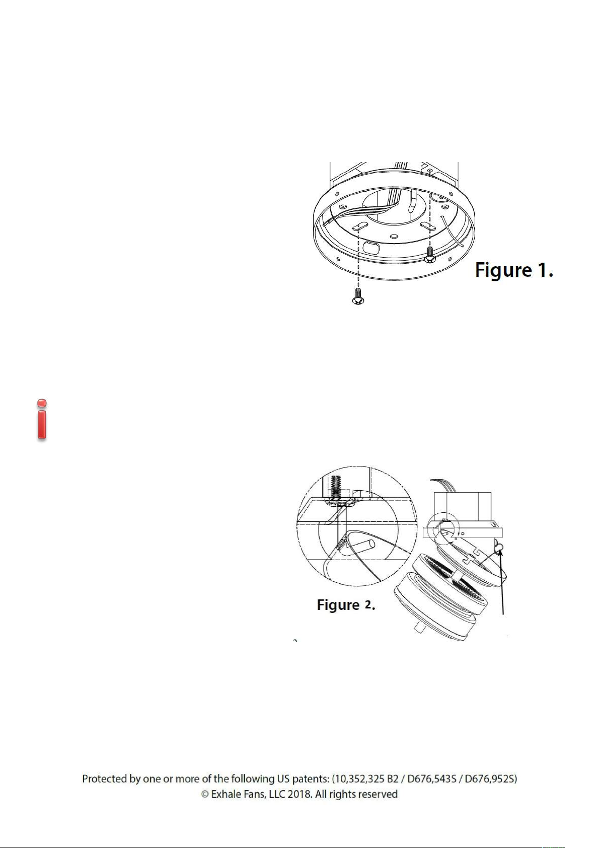
Step 4. Ceiling Mount
a. Pass the electrical wires from ceiling
through the ceiling mount center hole as
shown on Figure 1
b. Fix the support to the ceiling with
suitable screws
c. Using alevel make sure the mount is
plumb and level to the floor,adjust if
necessary.
d. The Exhale fan must be installed flat to
maintain its efficiency and service life
We offer asolution for inclined ceilings
up to 45 degrees with atilting rod,see
options or contact us
MODEL EF34
Installation in aconcrete ceiling requires optional mounting hardware
(see options page 11)
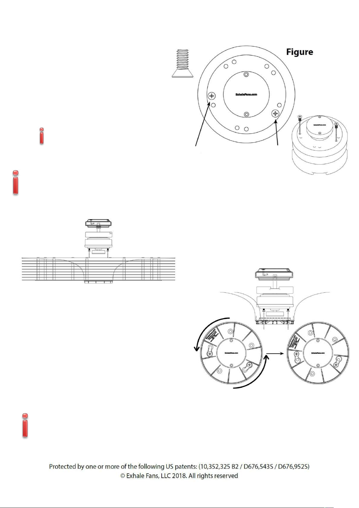
Step 5. Electrical Connections
Start by hanging the motor from the ceiling
mount hook as shown on figure 2and
secure the motor with the cable and pin.
a. Connect the fan neutral wire (black) to
the neutral household supply wire.
Connect the phase supply (red)to the
phase household supply.Connect the
ground fan wire (green and yellow)to
the ground household and secure the
motor with the cable and pin
(see figure 3)
Cable
b. After connecting all the wiring,spread them appart so that the green and red wires are located
on the one side of the electrical box and the black one on the other.
c. Turn the wire nuts upwards and push the wires neatly into electrical box so they are out of the
way

6
MODEL EF34
Red wire with household phase
Black wire with household neutral
Yellow / Green wire with household ground
Step 6Mounting the motor
Pre-install 2of the included #10-24 screws half-way
into the ceiling mount on either side
Install the motor onto the ceiling mount by sliding
the preinstalled bottom mount over the ceiling
mount as shown in figure 4
Using aclockwise twisting motion, the motor will
temporarily lock into the ceiling mount while you
install the remaining 2 #10-24 screws and tighten
all connections.
Figure 4.
Be sure an align the two twist lock channels with the 2
pre-installed screws added first
Household phase and neutral
ground
Phase = Red
Neutral = Black
Figure 3.
7
MODEL EF34 5.
Step 7. Hanging the Disc Array
a. Using only 2of the included ¼-20 flat head
motor mount screws,install them full rotation as
shown on figure 5
NOTE:these screws will be tightened
completely in alater step
WARNING:Not installing the screws a
full 2rotations could result in them
backing out and causing disc array to fall
prior to installing the remaining screws
Install 2motor mount screws
2full turns into the motor as
shown with the arrows.
b. Install the disc array onto the motor by
aligning the (2) scews installed earlier to
the key holes in the disc array as shown in
figure 7
Figure 6.
c. Rotate the entire disc array counter clockwise
to lock the screws into the disc array as shown
in figure 7.
NOTE:The disc array should be free hanging
from the (2) mounting screws.
d. Install the remaining (3) screws into the disc
array tightening all (5) using an alternating
pattern to ensure an even pressure is put on all
screws.
Figure 7.
WARNING:Not tightening the motor mounting screws propely could result in a
weak connection of disc array to the motor and cause the fan to become
unstable or fall.

8
Step 8. Install the plastic cover (If LED Option go to next step)
Install the plastic cover by sliding it over the centre of the disc block (see figure 8). The cover is held
in place by friction.There is no need to force it on, just push lightly
MODEL EF34
Figure 8.
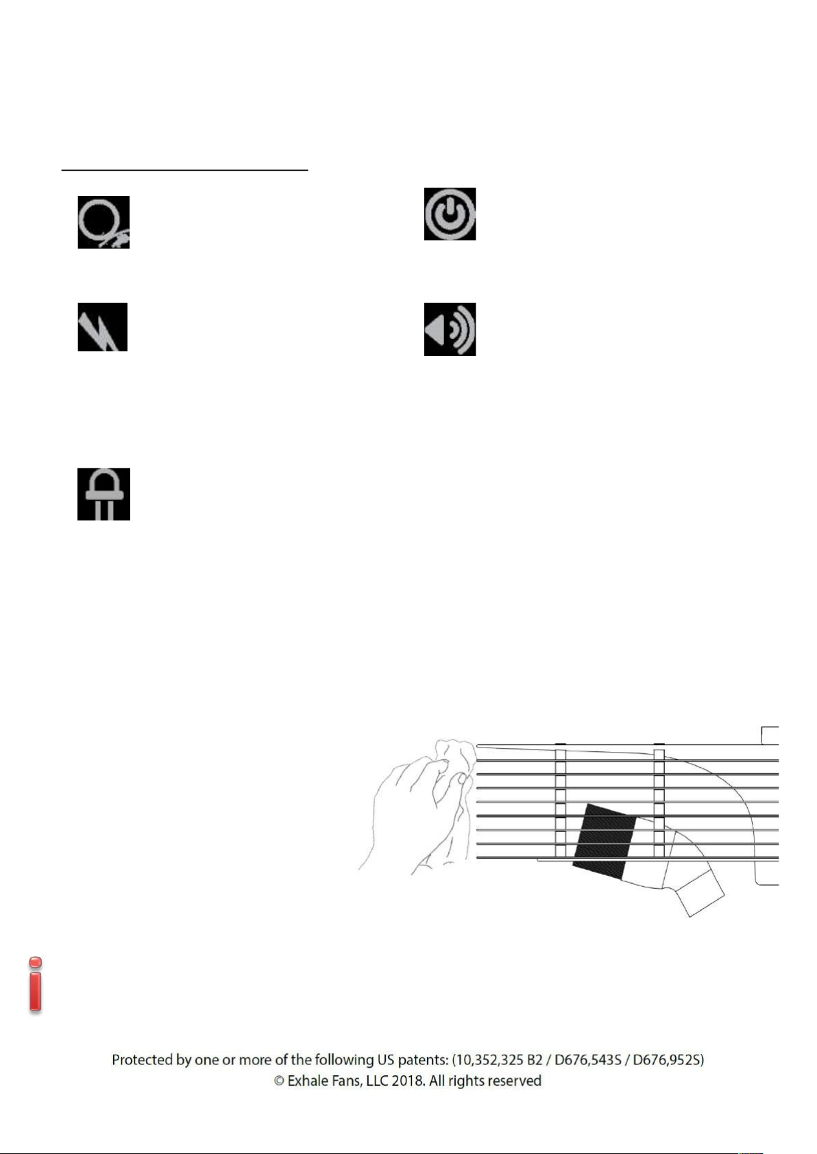
Remote Operation
SPEED DOWN
Changing the direction of rotation
clockwise (CW)
or anti-clockwise (CCW)
Light intensity adjustment
SPEED UP
Fan ON/OFF
LED light ON/OFF
FEATURES
Each remote is pre-programed to motor when packaged at the factory. However, we have added instructions
below on how to program the remote in the event that it may become necessary.
Install the two AAA 1.5 Volt Batteries into the remote transmitter by first removing the battery cover on the
back cover. Insert the batteries as indicated with the positive + end of the battery aligned with the + sign on
the battery holder

9
MODEL EF34
Remote Operation (cont.)
Operating Functions of the Remote:
The motor has 6speeds (1 to 6)
•To turn the fan ON and OFF select the button labeled POWER.
•To Increase or Decrease fan speed select SPEED UP or SPEED DOWN button.The illuminated
scale at the top of the remote will indicate the speed selected 1through 6.
•To change the direction of rotation, toggle the CW/CCW button for ClockWise direction or
CounterClockWise.With your Exhale Fan rotational direction is of personal preference,
performance and temperature are not affected.(if you have 2fans in the same room, we suggest
that you turn them in opposite directions to increase the air flow)
•Turning on the LED light is made by pressing the LED LIGHT ON/OFF button
•The LED DIMMER button is used to provide afull-scale dimmer function for your LED.Press and
Hold the dimmer button to select the level of illumination that you desire.While holding this
button the level of illumination will increase to 100%and then decrease to 20%, just release the
button at the level of illumination that you desire.
Remote Reprogramming (Syncing the remote)
•Turn the power OFF for at least 10 Seconds, if necessary, turn off the Circuit Breaker that routes
power to your fan.
•Turn Power to the Fan ON
•Within 60 seconds of turning the power on, press and hold the LED ON/OFF button for 5
seconds.Do not touch any other button during this process, doing so will cause this process to
fail.
•Once the Synchronization is completed and detected you will hear an audible “BEEP” which
indicates asuccessful synchronization.
•After completing the steps all fan functions will be available.
Please note that if a Power Failure occurs you may have select the CW / CCW direction button since
it is not remembered by the fan.

10
MODEL EF34
Optional Accessories
A- Concrete Mounting Hardware
Concrete mounting hardware MUST be used when installing directly to concrete without the use
of a juntion box.
Installation step 1-3 should be completed prior to installation of the ceiling mount.
a. Place the ceiling mount flush onto the
ceiling in the location where the fan will
be mounted.
b. Using the mount as a guide, mark the 4
bolt locations onto the ceiling where the
expansion anchors will be installed.
Expansion
anchors
Qty: 4
c. Remove the ceiling mount from the ceiling and check that the 4 locations marked are clear and
free from obstacles.
d. Using a 10 mm drill bit, drill the 4 bolt locations at least 40 mm deep into the concrete ceiling. (Be
sure to clean any remaining dust from the hole when finished).
Figure A.
e. Run the supply wires through the center of the
ceiling mount and secure the mount to the ceiling
using the included 4 expansion anchors.
f. [Refer to step 5. Electrical Connections]
g. Secure the fan safety cable from the motor to the
support hook by sliding open loop of the safety cable
over the hook and sliding the loop collar until its
tight around the saft of the hook as seen in figure A
h. [return to Installation Step 6. Munting the motor]
11
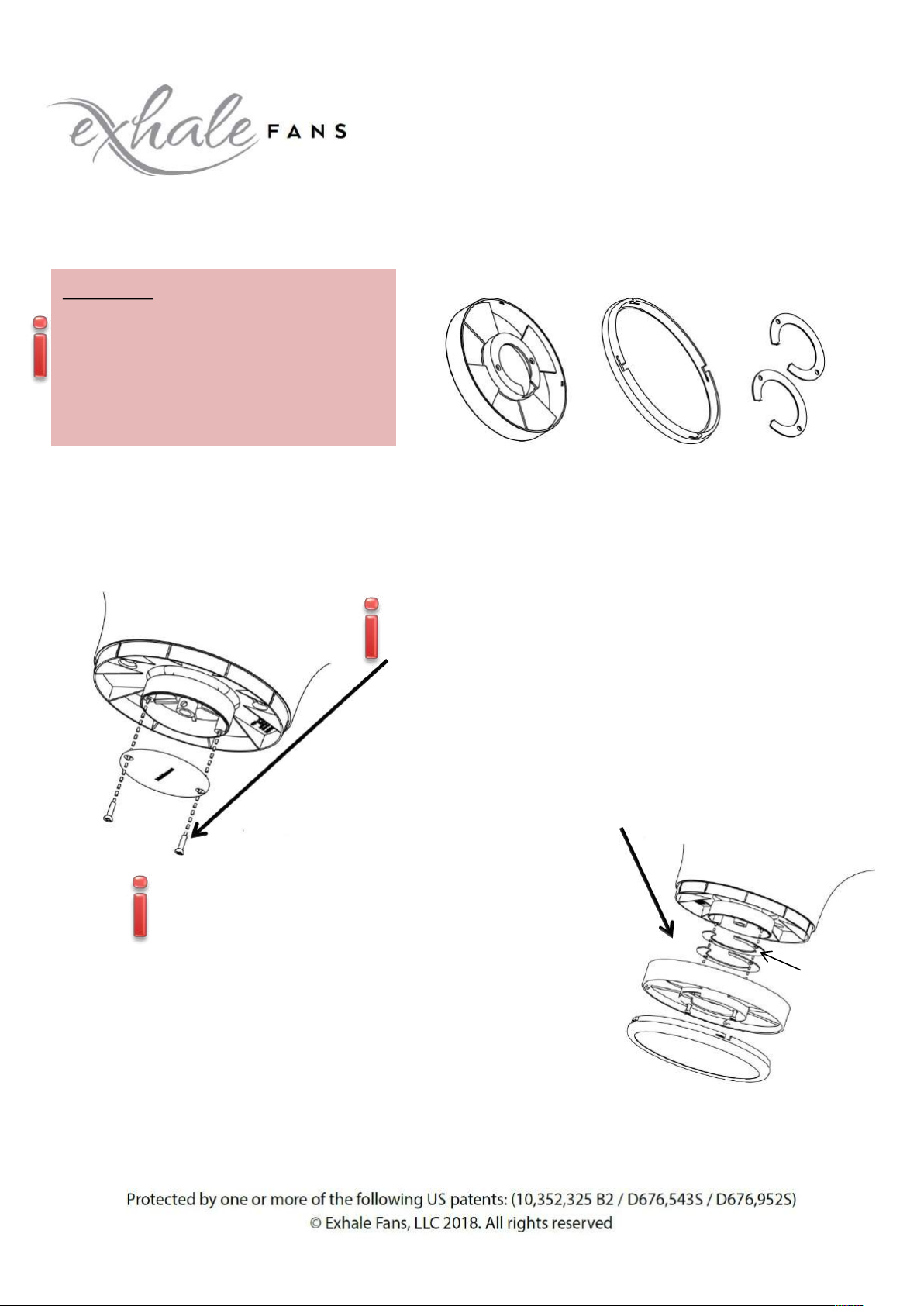
Optional Accessories (continued)
B. LEDS Lighting system
Part List:
Main housing LED Warm / Cool Spacers
WARNING:Turn off all electrical
power priorto making any
electrical connections.Failure
to do so will damage the led
and could result in electrical
shock,personal injury or death
a. Turn off all electrical power to the fan while making any electrical connections
b. Once the disc array has been installed, leveled, and you h-are happy with the operation,
remove the black cover located dirctly below the fan shown figure B
Figure B.
Please take the time to make sure the fan rotates freely
with the main LED housing
c. Mount the Main LED housing to the black lower housing of
the motor using the 2screws retained from the last step,shown
figure C. Note:You may need to use one or more of the included
spacers between the black lower housing and the main LED
housing to achieve clearance between the fan and the LED
lighting system to ensure smooth operation without rubbing.
Spacers
Retain the 2 mounting screws removed from the lower
housing, the will be used later
d. Make the appropriate electrical connection from the LED housing
to the motor.Note the connectors used from the motor to the LED
Housing are Male/Female and can only be installed one way!
e. Take care to tuck the wires into the lower housing using the main
housings cutaway as achannel to run the wires.
f. You can now line up the tangs of the main housing and gently rotate clockwise to lock them in
place.
Figure C.

12
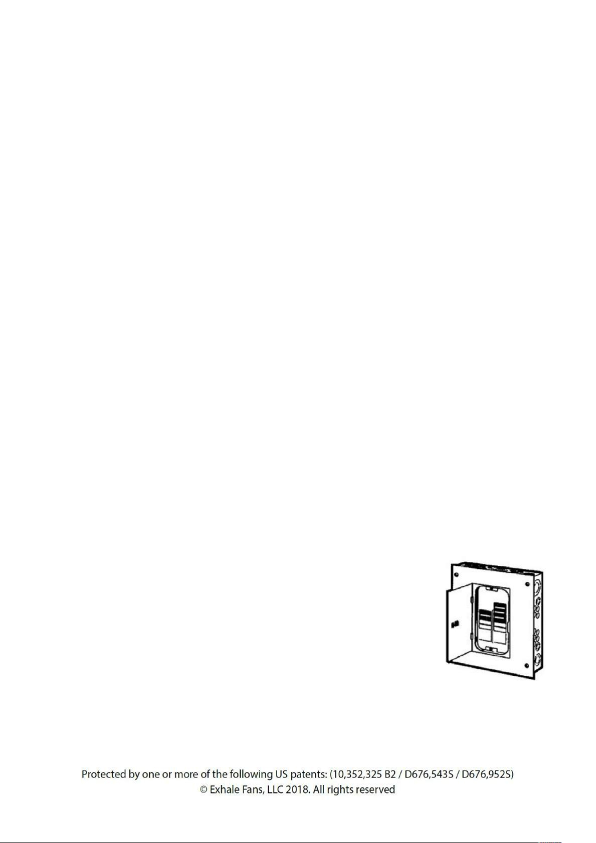
C. WIRELESS WALL SWITCH
MODEL EF34
POWER OFF
CHANGE FAN ROTATION
CW/ CCW
Optional Accessories (continued)
POWER ON
(from 1 to 6)
LIGHT ON/OFF
PROGRAMMER
1 -2 -4 -8 H
a. Installation
1- Fix the metal plate to
the wall using the 2
screws provided
2- on the back of the wall
switch –remove the
cover and place 2 AAA
batteries 1.5 V
3- Clip the switch control
to the wall bracket using
the built-in magnets
LIGHT DIMMER
20 to 100 %

13
MODEL EF34
Optional Accessories (continued)
b. Synchronisation of the wall switch (wireless wall control)
•Turn off the electricity at the electrical panel and wait at least 10 seconds.
•Reconnect the electricity
•Within 60 seconds of turning on the power, hold down the LED (orange) button (center button) until
you hear abeep (about 5-10 seconds).
*** Do not press any other button during this process or it will fail ***
•Once these steps are completed, all functions of the switch will be available.
Reprogramming /resynchronisation with several fans in the same room
If you want to pair several (up to 7) fans on the same remote control
1- switch off the power supply of all fans at the electrical panel for at least 10 sec
2- select the group of fans, power up only the desired fans and within 30 seconds of powering up
again,press and hold the ON/OFF LIGHT button on the remote control
3- Once the synchronization has been completed and detected,you will hear aBEEP SOUND on each
fan of the group which indicates asuccessful synchronization.
If you want to go back to the initial configuration, (i.e. one fan, one remote control) it is mandatory
to do it fan by fan:
1- switch off the power supply to all fans in the room and then power only the desired fan without
powering any other one.
2- Power up only the desired fan, within 30 seconds of powering up, hold down the LED ON/OFF
button for at least 10 sec.Make sure you do not press any other button,otherwise the process will
fail.
NB: A motor can have up to 2remote controls.If you wish to pair asecond remote control -repeat
the same operation with the second remote control.

14
MODEL EF34
Optional Accessories (continued)
D. EXTENDABLE AND TILTABLE ROD
This rod is suitable for fixing the fan to a sloping ceiling
It has 5 levels of adjustment (from 29 to 39 cms in total)
It supports slope angles of up to 45 degrees
It has been developed especially for Exhale fans
5 levels of adjustment
Tiltable from 0 to 45°
15
MODEL EF34
SPECIFICATIONS TECHNIQUES
DIMENSIONS
VOLTAGE OTIONS
Height
:
7,5 in / 18,4 cm
AC INPUT 220 V, 50 Hz
Width
:
34 in / 86,4 cm
50 W, max 0,5A
Weight
:
25 lbs / 11,4 kg
ENERGY USAGE
SOUND (dB)
Level
1
4 Watts , 120 RPM
Level
1
35.3 dB
Level
2
6 Watts , 158 RPM
Level
2
36.2 dB
Level
3
9 Watts , 198 RPM
Level
3
37.5 dB
Level
4
16 Watts , 236 RPM
Level
4
38.1 dB
Level
5
36 Watts , 274 RPM
Level
5
38.7 dB
Level
6
50 Watts , 312 RPM
Level
6
40.1 dB
(40 dB =
silent library)
OPTIONAL LED LIGHTING SYSTEM
Watts
15 at 100 %
Cool White
5500 K
Dimmable
20% at 100%
Warm White
3000 K
Lumens
1050 (WARM)
-1200 (COOL) à 100%
Cleaning and Maintenance
With any fan, dust will collect on the leading edges where the air passes over.
Using a damp cloth with a mild detergent, wipe the dust from the interior and exterior edges of
the discs.
Alternatively, you can use the brush
attachment of your vacuum cleaner to
remove dust collected on the interior
and exterior surfaces of the fan.
We recommend cleaning the fan once
a month to keep dust to a minimmum
and keep your fan running at its
optimum.
WARNING:Make sure the fan is turned off and is not spinning before attempting
to clean with either of the methods listed above.

16
MODEL EF34
LEXICON
LEVEL 1
Black metal mounting bracket with holes for
ceiling mounting.
On the circumference four threaded holes to
receive the 4 golden curved fixing screws for
connection with the top of the engine and this
support.
A hook for engine support the time of the
electrical connection with the ceiling wires.
LEVEL 2
Metal cup with 2 round holes and 2 oblong
holes for fixing with the screws above.
First fasten the screws 1 and 2 in the floor
bracket 1 and then insert the floor 2, turn it to
lock the motor and fix and lock the screws 3
and 4. Finish by blocking screws 1 and 2.
We see out of the central axis locked by a pin
the 3 wires and the cable of fixation.
LEVEL 3
Protective plastic box for Printed Circuit Board (PCB) Motor control and lighting by remote control.
This case has a flexible mounting on the central axis of the engine. Can slightly move.
LEVEL 4
The motor istelf. NO NOT OPEN.
LEVEL 5
Black plastic case for LED lighting support (warm W or Cold light C) or replacement cover.
Other manuals for EF34
3
Table of contents
Other Exhale Fans Fan manuals


