Exhausto RPT-20T User manual

RPT-20T
INSTRUCTIONS
•English
•Deutsch
•Français
•Svenska
•Norsk
•Dansk
3005928-2018-05-02

© 2016 OJ Electronics A/S
2© 2016 OJ Electronics A/S
INSTRUCTIONS
English.................................................................................. 3
Deutsch .............................................................................. 10
Français .............................................................................. 17
Svenska.............................................................................. 24
Norsk.................................................................................. 31
Dansk ................................................................................. 38

3
© 2016 OJ Electronics A/S
RPT-20T
© 2016 OJ Electronics A/S
LIST OF FIGURES
The following figures are located at the back of the instructions:
Fig. 1: Removing the front cover
Fig. 2: Terminal overview
Fig. 3: Connecting Modbus using RJ12 6P4C Connector
Fig. 4: Connecting Modbus using screw terminals
Fig. 5: Connecting Sensor to Channel 1
Fig. 6: Connecting Sensor to Channel 2
Fig. 7: Drill template
INTRODUCTION
RPT-20T is a touch room panel, with a user friendly graphical user
interface, specifically designed to control ventilation in a single
room. The room panel communicates with the OJ GreenZone™
module through Modbus interface, ensuring easy installation, high
comfort and low energy consumption.
The RPT-20T room panel has a built-in temperature sensor and
two channels for connecting sensors with 0-10 VDC output, also
ensuring easy installation of various room sensors.
PRODUCT PROGRAMME
Type Product
RPT-20T 2” Room panel with temperature sensor
FUNCTION
If screen saver is activated, press the screen once to enter the main
screen.
Instruction
English
INSTRUCTIONS
English.................................................................................. 3
Deutsch .............................................................................. 10
Français .............................................................................. 17
Svenska.............................................................................. 24
Norsk.................................................................................. 31
Dansk ................................................................................. 38

4© 2016 OJ Electronics A/S © 2016 OJ Electronics A/S
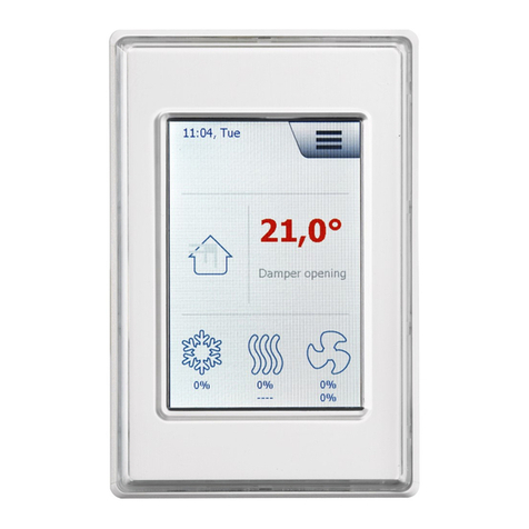
The screen give access to the basic control, like fan speed, tempe-
rature and setup. Time and date can also be read on the screen. If
an active alarm is present, a small alarm bell will be shown at the
display. The scope of this Quick Guide only includes a few basic
Setup features. A fully detailed description can be found online at
www.ojelectronics.com.
FAN SPEED
The user can select between four predefined fan speeds, Auto,
Low, High and O. At Auto mode, the RPT-20T will follow a
predefined schedule. In Low mode, the fan speed will override the
schedule and keep running at low fan speed for a given time; de-
fault 60 minuttes. In High mode, the fan will override the schedule
and keep running at high fan speed for a given time; default 60
minuttes. In O mode the fan will come to a complete stop until
next time user changes the fan speed mode.
TEMPERATURE
The user can change the temperature up or down, within a preset
range. The new temperature will be active until next event change
under Schedule.
SETUP OVERVIEW
If the RPT-20T is used together with a GreenZone™Master, all se-
tup are done through the GreenZone™Master and no Menu icon
will be shown. But used without a GreenZone™ Master, you will be
able to enter the Menu.
Please note that only Date and Time can be altered without use of
pin-code. First press the Menu icon in the upper right corner of the
screen. The will take you to the following screen:
RPT-20T English

© 2016 OJ Electronics A/S 5
© 2016 OJ Electronics A/S
HOME
Press this icon to return to the main screen.
SCHEDULE
Here you can setup a weekly schedule for fan speed and tempe-
ratures.
ROOM DATA
Gives you an overview with various sensor data for example tem-
perature, setpoints, PIR status and Windows contact status.
Now press the Down arrow once to enter the second Setup
screen:
ZONE COMPONENTS
Here it is possible to see status for all components in the current
zone. If an active alarm is present, the alarm code will be shown
here and an Alarm symbol will be show on the front screen (red
bell).
SETTINGS
Various settings for the Room Panel like Date, Time, Language etc.
RPT-20T English

6© 2016 OJ Electronics A/S © 2016 OJ Electronics A/S
HELP
Provides you with a on screen QR code for further help.
DATE AND TIME
Press the Settings icon. The screen will now switch to the Settings
screen:
Press the Date icon to enter Date settings:
Here you can change the date and change the format between
D/M/Y and M/D/Y. Press the back arrow to finish altering the date.
Press the Time icon to enter time settings:
Here you can change the time and change the format between
AM/PM and 24 Hours clock. Press the back arrow to finish altering
the time.
RPT-20T English

© 2016 OJ Electronics A/S 7
© 2016 OJ Electronics A/S
INSTALLATION
The RPT-20T is intended to be mounted in a wall socket. The
thermostat should be mounted on the wall approx. 1.5 m above
the floor in such a way as to allow free air circulation around
it. Draughts and direct sunlight or other heat sources must be
avoided.
The baseplate is equipped with multiple screw holes. Please use
the drill template for guidance; see fig. 7. The baseplate should be
fastened by minimum two screws tightened to a max. torque of
0.8 Nm.
CONNECTION MODBUS
You can connect the RPT-20T Room panel to a GreenZone Module
using a Modbus cable. The Modbus cable can connect to the RPT-
20T Room panel by a RJ12 6P4C connector or four single wires.
There is no dierence on features or behaviours using either RJ12
6P4C or screw terminals.
Modbus RJ12 6P4C
The Modbus cable is connected to a GreenZone Module Modbus
sensor port and the RJ12 6P4C port on the RPT-20T; see fig. 3.
Modbus Screw terminals
The Modbus cable can be connected to a GreenZone Module
Modbus sensor port and the corresponding screwterminals on the
RPT-20T; see. fig. 4.
RJ12 Screw terminal
1 +24V
2 GND
3 Bus “B”
4 Bus “A”
5 +24V
6 GND
CONNECTION OF SENSORS
It is possible to connect two sensors to the RPT-20T. The RPT-20T
has two channels with +24V output and 0-10V input; see fig. 5 and
6.
RPT-20T English

8© 2016 OJ Electronics A/S © 2016 OJ Electronics A/S
Sensor Screw terminal
1 - VCC +24V out (CH1)
1 - Out 0-10V in (CH1)
1 - GND GND (CH1)
2 - VCC +24V out (CH2)
2 - Out 0-10V in (CH2)
2 - GND GND (CH2)
TECHNICAL DATA
Supply voltage .............................24VDC +/-10%
Cable dimensions .......................10 x max. 0,75 mm²
Relative humidity....................0-95% (non-condensing)
Operating temperature ..........................-10/+40°C
Enclosure rating............................ IP21 (EN 60529)
Connection ................1xRJ12 6P4C, 10x screw terminals
Dimensions ........................82x82x41 mm.; see fig. 2
Mounted depth ...................................22 mm.
Max. Power consumption ...........................775 mW
Standby Power cumption ...........................500 mW
SERVICE AND MAINTENANCE
The RPT-20T Room panel contains no parts which require service
or maintenance.
Please contact your supplier in case of problems.
DISPOSAL AND ENVIRONMENTAL PROTECTION
Help protect the environment by disposing of the packaging and
redundant products in an environmentally responsible manner.
Products marked with this symbol must not be disposed of
together with household refuse but must be delivered to a
waste collection centre in accordance with applicable local
regulations.
CE MARKING
OJ Electronics A/S herewith declares that the product is in confor-
mity with the following directives of the European parliament:
EMC - electromagnetic compatibility: 2004/108/EU
RoHS - restriction of the use of certain hazardous substances:
2011/65/EU
RPT-20T English

© 2016 OJ Electronics A/S 9
© 2016 OJ Electronics A/S
Applied standards
EN 61000-6-2 and EN 61000-6-3 Electromagnetic Compatibility
(EMC).
RPT-20T English

© 2016 OJ Electronics A/S © 2016 OJ Electronics A/S
10 © 2016 OJ Electronics A/S
RPT-20T
Die Marke ist eine eingetragene Marke der OJ Electronics A/S · © 2016 OJ Electronics A/S
VERZEICHNIS DER ABBILDUNGEN
Die folgenden Abbildungen finden sich am Ende der Anleitung:
Abb. 1: Entfernen der Frontabdeckung
Abb. 2: Klemmenplan
Abb. 3: Anschluss des Modbus mit RJ12-6P4C-Stecker
Abb. 4: Anschluss des Modbus mit Schraubklemmen
Abb. 5: Anschluss eines Fühlers an Kanal 1
Abb. 6: Anschluss eines Fühlers an Kanal 2
Abb. 7: Bohrschablone
EINFÜHRUNG
RPT-20T ist ein Raumbediengerät mit benutzerfreundlichem, grafi-
schem Touchscreen-Display, besonders geeignet zur Lüftungsrege-
lung in einem einzelnen Raum. Das Raumbediengerät kommuniziert
mit einem OJ GreenZone™ Module über eine Modbus-Schnittstelle,
und sichert einfache Installation, hohen Komfort und niedrigen
Energieverbrauch.
Das RPT-20T-Raumbediengerät verfügt über einen eingebauten
Temperaturfühler und zwei Kanäle für den Anschluss von Fühlern
mit 0-10V=-Ausgang, einfache Installation einer Vielzahl von
Raumfühlern ermöglichend.
PRODUKTPROGRAMM
Typ Produkt
RPT-20T 2”-Raumbediengerät mit Temperaturfühlerr
BETRIEB
Ist der Bildschirmschoner aktiv, den Bildschirm für Zugri auf Haupt-
bildschirm einmal berühren.
Anleitung
Deutsch

© 2016 OJ Electronics A/S 11
© 2016 OJ Electronics A/S
Die Marke ist eine eingetragene Marke der OJ Electronics A/S · © 2016 OJ Electronics A/S
Auf diesem Bildschirm besteht Zugri auf grundlegende Parameter
wie Lüfterdrehzahl, Temperatur und Konfiguration. Auch Uhrzeit
und Datum sind auf dem Bildschirm ersichtlich. Bei aktivem Alarm
wird eine kleine Alarmglocke auf dem Bildschirm angezeigt werden.
Diese Kurzanleitung beschreibt nur ein paar grundlegende Konfigu-
rationsanweisungen. Die vollständige Anleitung findet sich online auf
www.ojelectronics.com.
LÜFTERDREHZAHL
Vier vorgegebene Lüfterdrehzahlen stehen zur Wahl: Auto, Niedrig,
Hoch und Aus. Im Auto-Modus folgt RPT-20T einem vorgegebe-
nen Zeitplan. Im Niedrig-Modus wird der vorgegebene Zeitplan
übersteuert und der Lüfter läuft über eine bestimmte Zeit (Standard
= 60 Minuten) mit niedriger Drehzahl. Im Hoch-Modus wird der
vorgegebene Zeitplan übersteuert und der Lüfter läuft über eine
bestimmte Zeit (Standard = 60 Minuten) mit hoher Drehzahl. Im
Aus-Modus kommt der Lüfter zu komplettem Stillstand bis die
Lüfterdrehzahl wieder geändert wird.
TEMPERATUR
Der Temperatursollwert lässt sich innerhalb eines vorgegebenen
Bereichs heben oder senken. Die neue Temperaturvorgabe bleibt
bis zum nächsten Phasenwechsel im Zeitplan aktiv.
KONFIGURATION
Kommt RPT-20T gemeinsam mit einem
OJ GreenZone™Master zur Anwendung, sind alle Parameter über
den OJ GreenZone™Master eingestellt und wird keine Menü-Iko-
ne auf dem Bildschirm angezeigt. Kommt RPT-20T ohne einem OJ
GreenZone™ Master zur Anwendung, besteht am Hauptbildschirm
Zugri auf das Menü.
Bitte beachten, dass nur Datum und Uhrzeit ohne Verwendung
eines PIN-Codes geändert werden können. Zuerst auf die Menü-
RPT-20T Deutsch

12 © 2016 OJ Electronics A/S © 2016 OJ Electronics A/S
Ikone in der Ecke rechts oben auf dem Bildschirm tippen. Der
folgende Bildschirm erscheint:
START
Auf diese Ikone tippen, um zum Hauptbildschirm zurückzukehren.
ZEITPLAN
Hier lässt sich ein wöchentlicher Zeitplan für Lüfterdrehzahl und
Temperatur einstellen.
RAUMDATEN
Bietet einen Überblick über verschiedene Fühlerdaten, z. B. Tem-
peratur, Sollwerte, PIR-Status und Fensterkontakt-Status.
Auf den Pfeil-nach-unten tippen, um zum zweiten Konfigurations-
bildschirm zu gelangen:
ZONENKOMPONENTEN
RPT-20T Deutsch

© 2016 OJ Electronics A/S 13
© 2016 OJ Electronics A/S
Hier wird der Status aller in der Zone befindlichen Komponenten
angezeigt. Wurde ein Alarm aktiviert, wird der Alarmcode hier
angezeigt und am Hauptbildschirm ein Alarmsymbol (eine rote
Glocke) angezeigt.
EINSTELLUNGEN
Hier lassen sich die verschiedenen Parameter für das Raumbe-
diengerät, einschließlich Datum, Uhrzeit, Sprache usw., einstellen.
HILFE
Zeigt am Bildschirm einen QR-Code an, mit dem sich Hilfe holen
lässt.
DATUM UND UHRZEIT
Auf die Einstellungen-Ikone tippen. Der Einstellungen-Bildschirm
wird angezeigt:
Für Zugri zur Datumseinstellung auf die Datum-Ikone tippen.
Hier lässt sich Datum und Datumsformat (T/M/J oder M/T/J) än-
dern. Nach erfolgten Änderungen auf den Zurück-Pfeil tippen um
zum Einstellungen-Bildschirm zurückzukehren.
RPT-20T Deutsch

14 © 2016 OJ Electronics A/S © 2016 OJ Electronics A/S
Für Zugri zur Uhrzeiteinstellung auf die Uhrzeit-Ikone tippen.
Hier lässt sich Uhrzeit und Uhrzeitformat (AM/PM oder 24-Stun-
den-Uhr) ändern. Nach erfolgten Änderungen auf den Zurück-Pfeil
tippen um zum Einstellungen-Bildschirm zurückzukehren.
INSTALLATION
RPT-20T ist für Montage in eine Wanddose vorgesehen. Das
Raumbediengerät ist auf einer Wand ca. 1,5 Meter über dem
Boden, dabei auf freie Luftzirkulation achtend, zu montieren.
Zugluft und direkte Sonneneinstrahlung oder andere Wärmequellen
müssen vermieden werden.
Die Bodenplatte ist mit mehreren Schraubenlöchern versehen. Die
Bohrschablone zur Markierung benutzen (siehe Abb. 7). Die Boden-
platte muss mit mindestens zwei Schrauben und einem Moment von
max. 0,8Nm festgemacht werden.
MODBUS-ANSCHLUSS
Das RTP-20T-Raumbediengerät kann über ein Modbus-Kabel mit
einem OJ GreenZone™ Module verbunden werden. Das Modbus-
Kabel ist mittels RJ12-6P4C-Stecker oder über vier Einzeldraht-
Schraubklemmen am RPT-20T-Raumbediengerät anzuschließen.
Für Eigenschaften oder Betrieb ergibt sich kein Unterschied, egal
ob der Anschluss über RJ12-6P4C-Stecker oder Schraubklemmen
erfolgt.
Modbus RJ12 6P4C
Das Modbus-Kabel an einen Modbus-Fühleranschluss am OJ
GreenZone™ Module und am RJ12-6P4C-Anschluss des RPT-20T
anschließen (siehe Abb. 3).
Modbus-Schraubklemmen
Das Modbus-Kabel an einen Modbus-Fühleranschluss am OJ
RPT-20T Deutsch

© 2016 OJ Electronics A/S 15
© 2016 OJ Electronics A/S
GreenZone™ Module und den entsprechenden Schraubklemmen
des RPT-20T anschließen (siehe Abb. 4).
RJ12 Schraubklemme
1 +24V
2 GND (Erde)
3 Bus “B”
4 Bus “A”
5 +24V
6 GND (Erde)
FÜHLERANSCHLUSS
Zwei Fühler können am RPT-20T angeschlossen werden. RPT-20T
verfügt über zwei Kanäle mit +24V-Ausgang und 0-10V-Eingang
(siehe Abb. 5 und 6).
Fühler Schraubklemme
1 - VCC +24V out (CH1)
1 - Out 0-10V in (CH1)
1 - GND GND (CH1)
2 - VCC +24V out (CH2)
2 - Out 0-10V in (CH2)
2 - GND GND (CH2)
TECHNISCHE DATEN
Versorgungsspannung ........................24V= ±10%
Kabelabmessungen......................10 × max. 0,75mm²
Relative Feuchte ................0-95% (nicht kondensierend)
Betriebstemperatur ............................ −10/+40°C
Schutzart .................................IP21 (EN 60529)
Anschlüsse ..............1 × RJ12 6P4C, 10 Schraubklemmen
Abmessungen ...................82×82×41mm (siehe Abb. 2)
Einbautiefe.......................................22mm.
Max. Stromverbrauch .............................775 mW
Standby-Stromverbrauch ..........................500 mW
SERVICE UND WARTUNG
Das RPT-20T-Raumbediengerät enthält keine Teile, die Service
oder Wartung erfordern.
Bei Problemen bitte mit dem Zulieferer Kontakt aufnehmen.
RPT-20T Deutsch

16 © 2016 OJ Electronics A/S
ENTSORGUNG UND UMWELTSCHUTZ
Helfen Sie mit, die Umwelt zu schützen durch umweltgerechte
Entsorgung der Verpackung und von gebrauchten Produkten.
Produkte mit dieser Kennzeichnung dürfen nicht als
normaler Hausmüll entsorgt werden, sondern sind gemäß
den geltenden lokalen Vorschriften gesondert einzusam-
meln.
CE-KENNZEICHNUNG
OJ Electronics A/S erklärt hiermit, dass das Produkt in Überein-
stimmung
mit den folgenden Richtlinien des Europäischen Parlaments ist:
EMV - Elektromagnetische Verträglichkeit: 2004/108/EU
RoHS - Beschränkung der Verwendung bestimmter gefährlicher
Stoe: 2011/65/EU
Angewandte Standards
EN 61000-6-2 und EN 61000-6-3 Elektromagnetische Verträglich-
keit (EMV).
RPT-20T Deutsch

17
RPT-20T
© 2016 OJ Electronics A/S
LISTE DES FIGURES
Les figures suivantes sont situées au dos des instructions :
Fig. 1: Enlever le couvercle frontal
Fig. 2: Aperçu des bornes
Fig. 3: Connexion du Modbus en utilisant le connecteur RJ12 6P4C
Fig. 4: Connexion du Modbus en utilisant les bornes à vis
Fig. 5: Connexion d’une sonde au canal 1
Fig. 6: Connexion d’une sonde au canal 2
Fig. 7: Gabarit de perçage
INTRODUCTION
Le RPT-20T est un panneau de pièce avec écran tactile convivial
et une interface graphique pour utilisateur spécifiquement conçue
pour contrôler la ventilation d’une seule pièce. Le panneau de pièce
communique avec un OJ GreenZone™ Module par une interface
Modbus assurant une installation facile, beaucoup de confort et une
faible consommation d’énergie.
Le panneau de pièce RPT-20T possède une sonde de température
intégrée et deux canaux pour raccorder des sondes avec une sortie
0-10 VCC permettant une installation facile de diverses sondes de
pièce.
GAMME DE PRODUITS
Type Produit
RPT-20T Panneau de pièce 2” avec sonde de température
FONCTIONNEMENT
Si l’écran de veille est actif, appuyez sur l’écran une fois pour accé-
der à l’écran principal.
Instruction
Français
La marque est une marque déposée d’OJ Electronics A/S · © 2016 OJ Electronics A/S

18 © 2016 OJ Electronics A/S © 2016 OJ Electronics A/S
L’écran vous donne accès aux contrôles de base comme la vitesse
du ventilateur, la température et le réglage. Vous pouvez également
voir l’heure et la date à l’écran. Si une alarme est activée, une pe-
tite cloche d’alarme s’achera à l’écran. Ce guide rapide ne décrit
que quelques instructions de base pour le réglage. Vous avez ac-
cès aux instructions complètes en ligne à www.ojelectronics.com.
VITESSE DU VENTILATEUR
Vous pouvez choisir parmi quatre vitesses prédéfinies du ventilateur:
Auto, Lent, Rapide et Arrêt. En mode Auto, le RPT-20T suit une pro-
grammation prédéfinie. En mode Lent, la programmation prédéfinie
est contournée et le ventilateur fonctionne à basse vitesse pendant
une durée donnée (par défaut = 60 minutes). En mode Rapide, la
programmation prédéfinie est contournée et le ventilateur fonctionne
à haute vitesse pendant une durée donnée (par défaut = 60 minutes).
En mode Arrêt, le ventilateur s’immobilise complètement jusqu’à vous
changiez la vitesse du ventilateur.
TEMPÉRATURE
Vous pouvez augmenter ou réduire le point de consigne de la
température dans les limites d’une plage préréglée. La nouvelle
température demeure active jusqu’au prochain changement d’évé-
nement de la programmation.
RÉGLAGE
Si le RPT-20T est utilisé avec un OJ GreenZone™Master, tous les
paramètres sont réglés par l’OJ GreenZone™Master et aucune
icône de menu n’apparaît à l’écran. Si le RPT-20T n’est pas utilisé
avec un OJ GreenZone™ Master, vous pourrez accéder au menu
principal par l’écran.
Notez qu’uniquement la date et l’heure peuvent être modifiées sans
utiliser un code NIP. En premier, appuyez sur l’icône de menu dans le
coin droit supérieur de l’écran. L’écran suivant s’achera:
RPT-20T Français

© 2016 OJ Electronics A/S 19
© 2016 OJ Electronics A/S
ACCUEIL
Appuyez sur cette icône pour retourner à l’écran principal.
PROGRAMME
Ici vous pouvez régler une programmation hebdomadaire pour la
vitesse du ventilateur et la température.
DONNÉES PIÈCE
Cet écran ache un aperçu des diverses données de sonde, par
ex., température, points de consigne, état PIR et état du contact
de fenêtre.
Vous pouvez également appuyer sur la flèche vers le bas pour
accéder au deuxième écran de réglage:
COMPOSANTS ZONE
Ici vous pouvez régler l’état pour toutes les composantes de la
zone courante. Si une alarme est activée, le code d’alarme s’a-
RPT-20T Français

20 © 2016 OJ Electronics A/S © 2016 OJ Electronics A/S
chera ici et un symbole d’alarme (une cloche rouge) s’achera sur
l’écran principal.
RÉGLAGES
Ici vous pouvez régler les diérents paramètres pour le panneau de
pièce incluant la date, l’heure, la langue, etc.
AIDE
Il fournit un code QR à l’écran que vous pouvez utiliser pour
obtenir de l’aide.
DATE ET HEURE
Appuyez sur l’icône des réglages. L’écran pour les réglages
s’achera:
Appuyez sur l’icône Date pour accéder aux réglages de la date:
Ici vous pouvez modifier la date et le format de la date (J/M/A ou
M/J/A). Quand vous avez eectué les changements requis, ap-
puyez sur la flèche de retour pour revenir à l’écran des réglages.
Appuyez sur l’icône Heure pour accéder aux réglages de l’heure:
RPT-20T Français
Table of contents
Languages:
Other Exhausto Touch Panel manuals
Popular Touch Panel manuals by other brands
IBASE Technology
IBASE Technology MRS-801-RE user manual
Vimar
Vimar 01422 quick start guide
IEI Technology
IEI Technology POC-W22A-H81 Quick installation guide
Balluff
Balluff BAE PD-VS-011-01 installation guide

Emerson
Emerson Site Supervisor 10.1 quick start guide
PROMULTIS
PROMULTIS PM-TL43A/PCAP instruction manual
