Exhausto TENDER ESL315 60 User manual

EXHAUSTO A/S
Odensevej 76
DK-5550 Langeskov
Tel. +45 65 66 12 34
Fax +45 65 66 11 10
exhausto@exhausto.dk
www.exhausto.dk
3003932-2010-06-01.fm
Bedienungsanleitung, Seite 2 - 6
User instructions, page 7 - 11
TENDER
ESL315_60

3003932-2010-06-01.fm
2/12
Installation
Die Küchenhaube TENDER ist für Wandmontage
konstruiert.
Die Küchenhaube ist mit motorangetriebener Klappe,
Halogenlampen und Metallfettfilter ausgerüstet.
Diese Anleitung enthält Hinweise über Installation,
Wartung u.a.m.
Technische Daten:
Abmessungen: siehe Abb. 1
Elektrischer Anschluss: 230 V mit Erdung
Beleuchtung: Halogenglühlampe 12 V,
20 W, Sockel G4
Installation
Montageteile, Schrauben für die Montage u.a.m.
werden mit der Küchenhaube mitgeliefert.
Die Abführung der Abluft muss nach den geltenden
Vorschriften der zuständigen Behörden ausgeführt
werden.
Die Abluft darf nicht zu einem Abzugskanal geführt
werden, der zur Abführung von Rauchgasen von z.B.
Gasöfen, Kaminöfen, Ölöfen u.dgl. benutzt wird.
Montageteile, Abb. 2
• 2 Stck. Beschläge für das obere Abzugsrohr
• 7 Stck. Dübel
• Schrauben
Montage von Wandbeschlägen, Markierung an
der Wand, Abb. 2:
Der Abstand zwischen dem Herd und der Küchen-
haube muss mindestens 50 cm betragen. Bei einem
Gasherd muss der Abstand 65 cm betragen. Falls der
Hersteller des Gasherdes einen größeren
Montageabstand empfiehlt, ist dieser einzuhalten.
Hinweis!
Der maximale Abstand zwischen der Unterkante der
Küchenhaube und der Oberkante des Abzugsrohres
beträgt 1190 mm. Bei Montage mit einer
Verlängerung des oberen Abzugsrohres, siehe bitte
die entsprechenden Maßangaben.
1
2

3003932-2010-06-01.fm
3/12
• Eine Mittellinie A über dem Kochfeld an der Stelle
markieren, wo die Küchenhaube montiert werden
soll.
• Eine waagerechte Bezugslinie B 500/650 mm über
dem Kochfeld ziehen.
• Den oberen Beschlag D wie auf der Skizze darg-
estellt an der Wand montieren, Abb. 2.
• Die Bohrpunkte an der Wand anreißen.
• Den mittleren Beschlag für das Abzugsrohr D an
der Wand, 385 mm unter dem oberen Beschlag
anbringen, und die Bohrpunkte für den Beschlag
an der Wand anreißen.
• Die Bohrpunkte für die Aufhängung C der Küchen-
haube wie auf der Abbildung dargestellt an der
Wand anreißen.
• Ein Loch von Ø2,8 mm mittig in den jeweiligen
Markierungen bohren.
• Die Beschläge mit den Schrauben F (4,5 x 32 mm)
am Schornstein befestigen.
Wenn die mitgelieferten Dübel benutzt werden sollen,
sind Löcher von 5,5 mm zu bohren. Die Dübel E in die
Bohrungen einsetzen. Darauf achten, dass die Dübel für
das Wandmaterial eeignet sind.
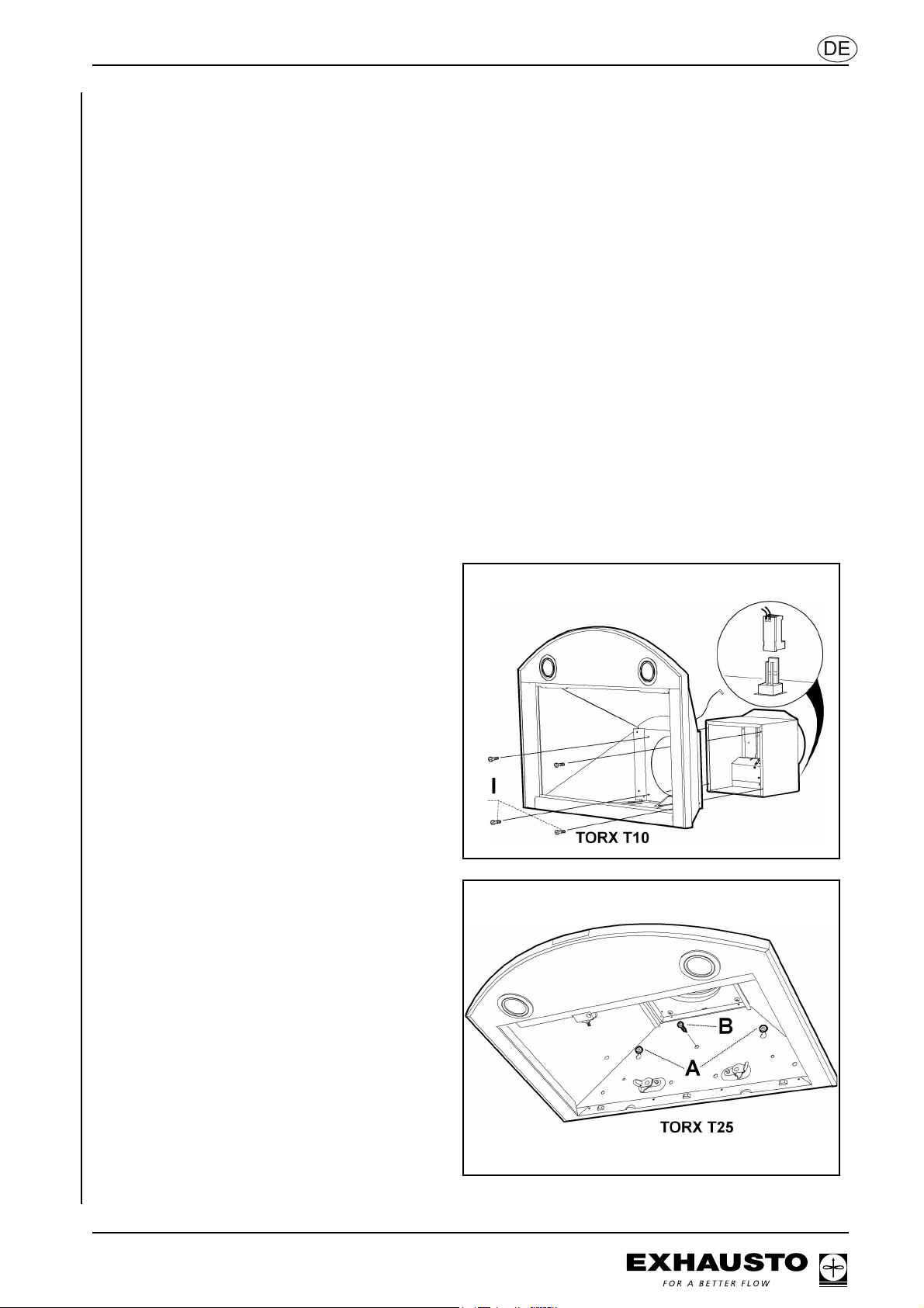
Montage der Klappeneinheit, Abb. 3
• Fettfilter entfernen, Abb. 8.
• Gebläse und Klappeneinheit auf einer ebenen
Fläche anbringen.
• Die Klappeneinheit im Gebläse mit den
Schrauben ”I” befestigen.
• Das Regelkabel für die Klappe an den Stecker
auf der Oberseite der Klappeneinheit
anschließen, Abb. 3.
Montage der Küchenhaube, Abb. 4
• Die 2 Schrauben ”F” (für Schlüssellochkerbe)
eindrehen jedoch nicht anziehen (4A).
• Die Küchenhaube an den Schlüssellochkerben
einhängen.
• Die Küchenhaube einstellen und die Schrauben
anziehen.
• Die Küchenhaube mit einer Schraube ”F” (4B)
arretieren.
3
4

3003932-2010-06-01.fm
4/12
Die Küchenhaube mit einem Rohr oder Schlauch Ø
160 mm anschließen. Bei einem Ø125 mm-
Anschluss ist ein Anschlussadapter erforderlich.
Hinweis!
Bei Montage mit einem Schlauch ist der Schlauch
straff am Anschluss zu montieren, Abb. 5
Elektrische Installation
Das Elektrokabel anschließen.
Die Steckdose montieren wie auf der Skizze
dargestellt (Abb.3). Wenn die Küchenhaube mit
einem verlängerten oberen Abzugsrohr montiert
wird, ist dies bei der Positionierung der
Steckdose zu berücksichtigen.
Die Küchenhaube wird mit Kabel und Stecker mit
Schutzkontakt für den Anschluss an eine geerdete
Steckdose geliefert.
Die Steckdose muss nach der Montage zugänglich
sein. Jeder anderer Anschluss oder der Austausch
des Kabels muss von einem Fachmann ausgeführt
werden.
Einstellen der Klappe:
Siehe gesonderte Anleitung, Dokument Nr. 3003930.
Montage des Abzugsrohres (Abb. 6):
Abzugsrohr, Sektion oben:
• Die beiden Seiten der oberen Sektion vorsichtig
nach außen bewegen und in die Beschläge "D"
einhängen, bis sie einrasten. Auf korrekten Sitz
kontrollieren.
• Die Seiten der oberen Sektion mit den
2 Schrauben ”G” (2,9 x 9,5 TORX T10) an den
Beschlägen befestigen.
Abzugsrohr, Sektion unten:
• Die beiden Seiten der unteren Sektion nach außen
bewegen und vorsichtig auf die Küchenhaube absetzen.
• Die untere Sektion unten einhängen.
• Die Sektion nach unten drücken, bis sie in den Rand
der Küchenhaube passt.
• Die Oberkante in die obere Sektion und in die Wand
einhängen – sie muss einrasten.
Verwertung von Verpackung und Produkten
Die Verpackung ist an einer Sammelstelle
zur Verwertung abzugeben. Das Symbol gibt
an, dass das Produkt nicht als Hausmüll
gehandhabt werden darf. Es ist stattdessen
an einen Sammelplatz zur Verwertung von
Elektro- und Elektronikkomponenten abzugeben. Durch
die Gewährleistung korrekter Handhabung tragen Sie
zur Vorbeugung etwaiger negativer Umwelt- und
Gesundheits-beeinträchtigungen bei, die bei der
Entsorgung als Hausmüll entstehen könnten.
Zusätzliche Informationen über Verwertung erhalten Sie
von den Behörden vor Ort oder vom Fachhändler, wo
das Produkt gekauft wurde.
5
6

3003932-2010-06-01.fm
5/12
Bedienungsanleitung
Anwendung
Unter keinen Umständen unter der Küchenhaube
flambieren!
Wenn die Küchenhaube und gleichzeitig andere
Geräte, die mit einer anderen Energieform als Strom
betrieben werden, beispielsweise Gasherd,
Gasofen, Ölheizung oder Kaminofen, eingeschaltet
sind, muss genügende Luftzufuhr zum Raum
gewährleistet sein.
Wenn das Produkt von Kindern oder von Personen
mit verminderten mentalen, sensorischen oder
körperlichen Fähigkeiten benutzt werden soll, sind
diese Personen über die Benutzung des Produktes
zu informieren.
Funktion von Schaltern, Abb. 7
A Beleuchtung
B Klappenfunktion
C Anzeigelampe (leuchtet bei geöffneter Klappe)
Beim Kochen:
• Die Klappe durch Drücken auf B öffnen
• Die Klappe lässt sich durch Drücken auf B
wieder
schließen
• Nach 60 Min. schließt die Klappe automatisch
• Die Klappe sollte einen Moment vor und nach
dem
Kochen geöffnet sein, damit sich keine Koch-
dünste
im Raum ausbreiten
Pflege und Wartung
Reinigung
Das Risiko für die Ausbreitung eines Feuers steigt,
wenn die Küchenhaube nicht nach den Anweisun-
gen gereinigt wird:
• Die Fettfilter sind bei normaler Nutzung mind-
estens alle zwei Monate zu reinigen. Bei häu-
figer Nutzung öfter reinigen.
• Die Küchenhaube innen mindestens zwei Mal
im Jahr reinigen.
Die Fettfilter in der Spülmaschine spülen oder in
warmem Wasser mit Spülmittel einweichen. Die
übrigen Teile der Küchenhaube mit einem feuchten
Tuch mit Spülmittel abwischen.
Die Fettfilter durch Öffnen der Schlösser entfernen.
Die Fettfilter vorsichtig handhaben, damit sie nicht
verbiegen. Die Fettfilter nach der Reinigung
montieren und kontrollieren, dass sie korrekt
einrasten.
7
8

3003932-2010-06-01.fm
6/12
GB
Austausch von Halogenglühlampen, Abb. 9.
Hinweis! Risiko für Verbrennung!
Vor dem Austausch von Glühlampen die
Spannungsversorgung unterbrechen.
Die Glühlampe vor dem Austausch abkühlen lassen.
• Die Schutzverglasung mit Hilfe des mitgeliefer-
ten Saugnapfes lösen, Abb. 9.
• Die Glühbirne ist jetzt für den Austausch
zugänglich. (Halogenglühlampe 12 V, 20 W,
Sockel G4).
• Direkte Berührung der Glühlampe vermeiden.
Hinweis: Die Schutzverglasung ohne den
Saugnapf montieren.
Fehlersuche und Wartung
Kontrollieren, dass der elektrische Anschluss korrekt
und die Sicherung einwandfrei ist. Die Beleuchtung
und alle Drehzahlen testen um zu kontrollieren, dass
alles korrekt funktioniert.
DTS Dansk Total Service
Wenn Sie Unterstützung zur Abhilfe eines Fehlers
oder Information über eine Kundendienstwerkstatt in
Ihrer Nähe benötigen, wo Sie schnellen und guten
Service bekommen, dann rufen Sie bitte die
Kundendienstabteilung von FRANKE Futurum unter
der Telefonnummer +46 (0) 912-40 500 an.
Das Produkt ist von den geltenden Normen und
Vorschriften umfasst.
9

3003932-2010-06-01.fm
7/12
GB
Fitting
Installation
The TENDER cooker hood is designed to be wall
mounted.
The cooker hood has a motor driven damper,
halogen lighting, and a metal wire filter.
Installation and maintenance information etc. are
provided in this guide.
Technical data
Dimensions: see fig. 1
Electrical connection: 230 VAC, earthed.
Lighting: Halogen bulbs, 12 V, 20 W,
G4 socket
Fitting
Components and screws for fitting, etc., are
supplied with the cooker hood.
Extract air must be removed in accordance with
regulatory requirements.
Extract air may not be diverted to exhaust ducts used
to carry flue gases from gas fireplaces, wood stoves
or oil-fired boilers, etc.
Installing wall fittings, marking the wall, fig. 2
There must be a minimum distance of 50 cm between
the cooker and the cooker hood. For gas cookers this
distance must be at least 65 cm. If the manufacturer
of the gas cooker recommends a greater distance,
this must be respected.
NB:
The maximum distance between the bottom edge
of the cooker hood and the top edge of the
extraction pipe is 1,190 mm. For installation using
an extended top extraction pipe, please refer to
the specifications for this.
• Mark a centre line (A) above the cooker showing
where the cooker hood is to be fitted.
• Draw a horizontal reference line (B) 500/650
mm above the cooker
• Place the top bracket (D) on the wall as shown
in fig. 3.
• Mark the holes for the screws on the wall.
• Position the middle extraction pipe bracket (D)
on the wall 385 mm below the top bracket and
mark the screw holes for the bracket on the wall.
1
2

3003932-2010-06-01.fm
8/12
GB
• Mark the screw holes for mounting the cooker
hood (C) on the wall as shown in the figure
• Drill Ø 2.8 mm holes in the centre of each mark.
Screw the brackets onto the chimney using the
4.5 x 32 mm screws (F)
• If the supplied Rawl plugs are to be used, drill
5.5 mm holes. Place the plugs (E) in the holes.
Check that the plugs are appropriate for the
given wall material.
Fitting the damper unit, fig. 3
• Remove the grease filter, Fig. 8
• Position blower and damper unit on a level sur-
face
• Fix the damper unit in the blower with the
screws “I”
• Connect the damper control cable to the plug on
the damper’s top side, Fig. 3.
Fitting the cooker hood, Fig. 4
• Screw in two screws “F” (for keyhole mounting)
without tightening them (4A)
• Hook the cooker hood up in the keyholes
• Adjust the cooker hood and tighten the screws
• Lock the cooker hood with a screw “F” (4B)
Connection to ventilation duct
Connect the cooker hood using a Ø 160 mm pipe or
hose. If the connection is Ø 125 mm, a transition
coupling will be required.
NB: Where a hose is used, it must be attached,
extended, to the nearest connection (fig 5).
3
4
5

3003932-2010-06-01.fm
9/12
GB
Electrical installation
Attach the power cable
The cooker hood is supplied with cable and earthed
plug for connection to an earthed supply socket.
The plug is fitted as shown in the diagram (Fig. 3). If
the cooker hood is fitted with an extended upper vent,
the plug positioning must take this into consideration.
The power socket must be accessible when the
installation is complete. Any other type of connection,
or cable replacement, requires a technician.
Damper adjustment:
See separate instructions, document no. 3003930.
Fitting of vent (Fig. 6):
Vent, top section:
• Carefully pull the top section’s two sides out-
wards and affix them on the brackets (D), so
they fall into place. Check that the top section is
positioned correctly.
• Securely fix the top section sides to the brackets
using the two screws “G” (2.9 x 9.5 TORX T10)
Vent, lower section:
• Pull the lower section’s two sides out and carefully
secure them onto the cooker hood
• Securely hook on the lower section at the lower
end
• Push it down, so it is aligned with the cooker hood
edge
• Securely hook up the upper edge in the top sec-
tion and wall – make sure that the top edge fits
into place.
Product and packaging recycling
The packaging should be sent to a recycling
centre for recycling. The symbol indicates
that the product may not be treated as
household waste. It should instead be taken
to a collection point for recycling electrical
and electronic components. Correct handling of the
waste helps prevent any negative environmental and
health impacts which could arise from disposal as
normal waste.
For further information about recycling, please contact
the local authorities or the store at which the product
was purchased.
6

3003932-2010-06-01.fm
10/12
User instructions
Application:
Do not flambé food under the cooker hood.
The room should be adequately ventilated when the
cooker hood is used with products which use an
energy source other than electricity, such as a gas
stove or fireplace, oil-fired boiler, or wood stove.
Children or people with reduced mental, sensory or
physical capacity must be instructed on how to use
the product before using it.
Function switches, fig. 7.
A Lighting
BDamper
C Indicator lamp (lit when damper open)
During cooking:
• open the damper by pressing B
• the damper may be closed again by pressing B
• the damper will close automatically after one hour
• Leave the damper open for some time before and
after cooking to prevent cooking odours spread-
ing within the room.
Care and maintenance
Cleaning
The risk of fire propagation is increased if the cooker
hood is not cleaned as instructed:
• the grease filters should be cleaned at least
every two months during normal use. Clean
more often during frequent use
• the interior of the cooker hood should be
cleaned at least twice a year.
Grease filters may be washed in a dishwasher, or
soaked in warm water and detergent. The rest of the
cooker hood should be wiped with a damp cloth and
detergent.
Remove the grease filters by opening the locks.
Carefully remove the grease filters - avoid bending
them. Fit the cleaned grease filters and check that
they are locked correctly.
7
8

3003932-2010-06-01.fm
11/12
Changing a halogen bulb, fig. 9
NB: Risk of burn.
Disconnect the power when replacing a bulb.
Let the light cool before replacement.
• Loosen the lap glass using the suction cup pro-
vided. Fig. 9.
• The bulb can now be accessed for replacement.
(Halogen bulb, 12 V, 20W, G4 socket).
• Avoid direct contact with the bulb.
NB: Replace the lamp glass without using the
suction cup.
Troubleshooting and service
Check that the electrical connection is correct and the
fuse is intact. Test the lighting and all fan speeds to
ensure everything is working correctly.
DTS Dansk Total Service
Call FRANKE Futurum’s service department on
+46 (0) 912-40 500 for assistance in resolving any
fault, or referral to your nearest service centre, where
you can receive fast, quality service.
The product is covered by the applicable standards
and regulations.
9

EXHAUSTO A/S
Odensevej 76
DK-5550 Langeskov
Tel.: +45 6566 1234
Fax: +45 6566 1110
exhausto@exhausto.dk
www.exhausto.dk
EXHAUSTO GmbH
Am Ockenheimer Graben 40
D-55411 Bingen-Kempten
Tel.: +49 6721 9178-112
Fax: +49 6721 9178-97
info@exhausto.de
www.exhausto.de
EXHAUSTO NORGE A/S
Industriveien 25
N-2021 Skedsmokorset
Tel.: +47 6387 0770
Fax: +47 6387 0771
post@exhausto.no
www.exhausto.no
EXHAUSTO Ventilation Ltd.
Unit 1, Pelham Court
Pelham Place
Broadfield - Crawley
West Sussex - RH11 9SH
Tel. +44 (0) 1293 511555
Fax +44 (0) 1293 533888
info@exhausto-ventilation.co.uk
www.exhausto-ventilation.co.uk
EXHAUSTO AB
Verkstadsgatan 13
S-542 33 Mariestad
Tel.: +46 501 39 33 40
Fax: +46 501 39 33 41
info@exhausto.se
www.exhausto.se
SCAN-PRO AG
Postfach 74
CH-8117 Fällanden
Tel.: +41 43 355 34 00
Fax: +41 43 355 34 09
info@scanpro.ch
www.scanpro.ch
EXHAUSTO Suomi
Nummiperkontie 21
FI-21250 Masku
Tel.: +358 45 113 2628
Fax: +358 2 432 0013
info@exhausto-ventilation.fi
www.exhausto-ventilation.com
INATHERM B.V.
Vijzelweg 10
NL-5145 NK Waalwijk
Tel.: +31 416 317 830
Fax: +31 416 342 755
www.inatherm.nl
BM Vallá hf
Stórhöfda 23
IS-110 Reykjavik
Tel.: +354 530 3400
Fax: +354 530 3401
bmvalla@bmvalla.is
www.bmvalla.is
3003932-2010-06-01.fm
Table of contents
Languages:
Other Exhausto Ventilation Hood manuals
Popular Ventilation Hood manuals by other brands

Zephyr
Zephyr Pisa ZPI-E30AG290 Use, care and installation guide

AEG
AEG X76263MK1 user manual

Miele
Miele DAS 4720 Operating and installation instructions

Whirlpool
Whirlpool RH2630XJ Installation information

Whirlpool
Whirlpool HE36W Health & safety, use & care and installation guide

ILVE
ILVE CS Series Instruction manual & user guide