UK |7
3112027_BD_UK
Warning
To minimise the risk of fire, electric shock, personal injury
and/or damage to the product please observe the following:
• Please always read the manual and only use the product in accordance with the
manufacturer’s instructions. If in doubt, contact one of the Exodraft specialized dealers.
• All installations must be carried out by properly qualifi ed personnel in accordance with
national legislation and regulations.
• Prior to servicing the product, the heat source must be shut off and cooled down.
• Please ensure that the heat source is not turned back on inadvertently.
• A safety thermostat (ST110) and/or safety valve must be installed and connected to the
burner, ensuring disconnection in case of excessive temperatures. The switch must comply
with EN 14597.
UK
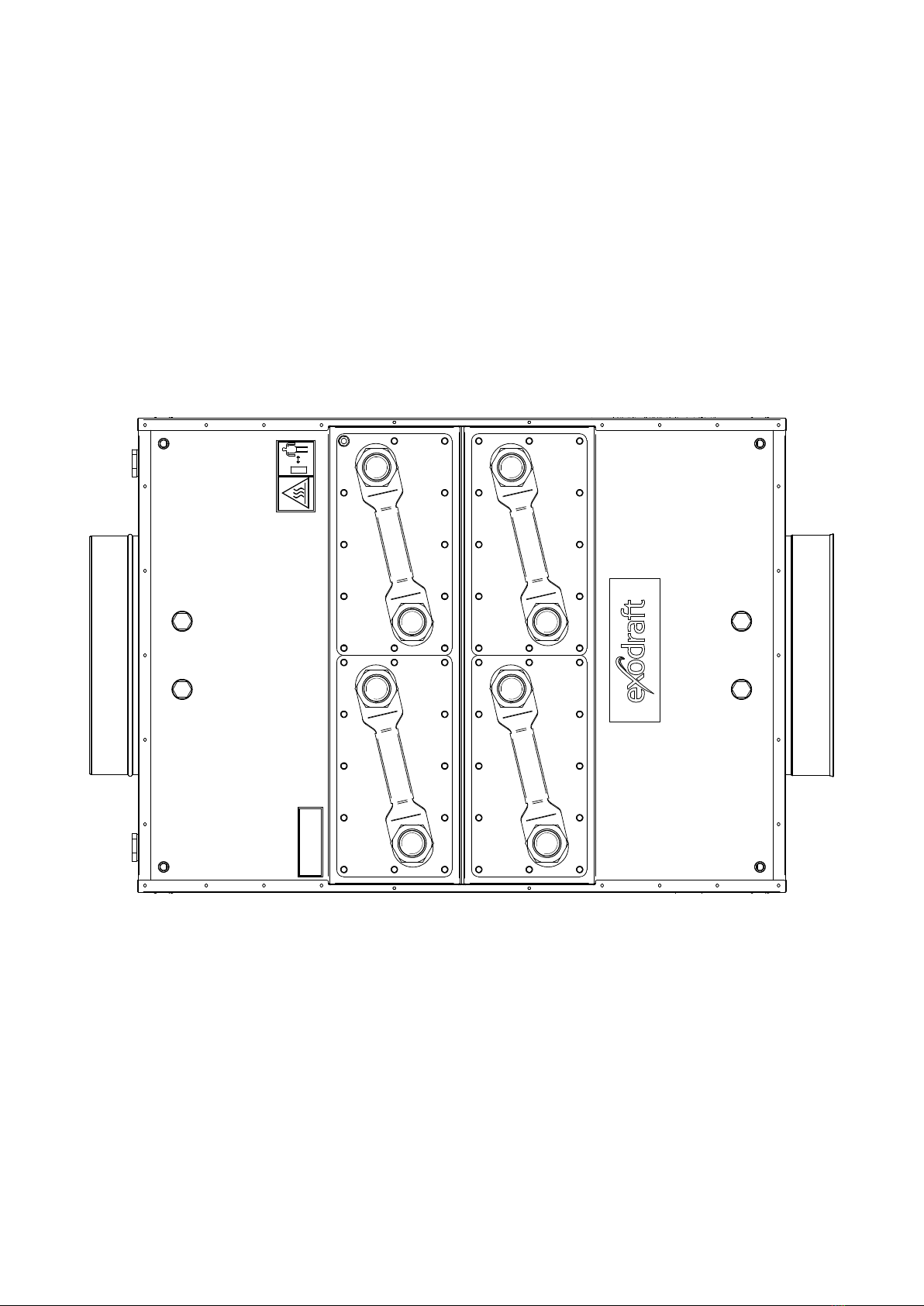
Product information
The Exodraft Bypass Damper is used in exhaust systems to control the hot ue gases/process air to the
Basic Plate heat recovery devices.
A Bypass Damper is used primarily for larger boiler systems, industrial processing plants, or commercial
systems. An integrated electric motor opens and closes the damper.
Power supply and start/stop signal come from an external Exodraft panel, and is not a part of the Bypass
Damper.
The Bypass Damper has a safety spring return, causing it to close automatically in case of a power failure.
All parts affected by ue gas are made of stainless steel EN 1.4404.
All exterior parts are made of stainless steel EN 1.4301.
The Bypass Dampers limitations
• The Bypass Damper is not to be used as a draining point in an exhaust system.
• As a rule, the Bypass Damper is only for indoor installation.
Installation outside requires extra shielding.
• Max. temperature 600°C
• Flue gas/process air must be of a quality (particle free) that will not, over time, cause the damper to be
lled with residue that can affect the function of the damper.
To nd out more about heat recovery visit www.exodraft.com
Scope of supply
• Exodraft Bypass Damper
• Installation manual and user instructions
• Pallet*
• Straps*
• Screws*
• Transportation safety brackets*
*For transportation only. Be aware to disconnect these parts before installation.