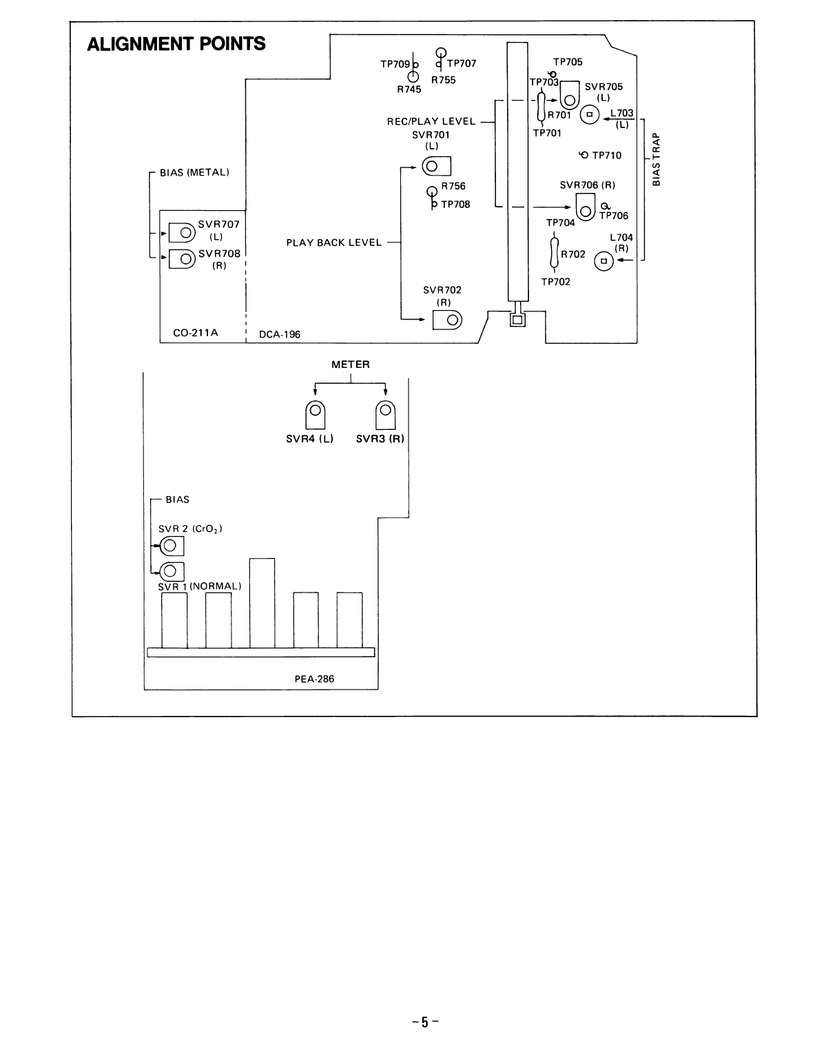
ALIGNMENT PROCEDURE
4l Bias Trap / Bias Voltage A ,^ , ,,
TP7071708
B IAS-OSC APPROX. 60KHz
OSC
TP705 /706
R ECOR D EO AMP
NOTE: The Bias Voltages indicated in the above table do not necessarily correspond to the best recording character-
istics of dynamic range, distortion, frequency response, etc.
Make some adjustments according to the best values actually obtained.
5) Recording Level Caliblation DOLBY AMP R ECOR D EO AMP {-ADJ
RIP
LINE IN
400H2
H EAD
ADJUSTMENT (A) (BIAS TRAP)
Controls to be positioned Test Tape P roced u re
Dolby NR : OFF
MPX : OFF
Tape Selector . METAL
Function : R EC.
Blank Ad justing L703 , 704 to m in. ind ication on the
V.M. scale at the Test point of TP7 07 and 708.
(GND: TP709)
ADJUSTMENT (B) (BIAS VOLTAGE)
Dolby NR : OFF
MPX : OFF
Tape Selector : METAL
J
EXTRA
J
NOR MAL
Blank
Metal
X L-II
B H F-60
1) Connect V.M. across TP7011703 and TP7021704.
Step ITa pe Se lecto rAppro x.
Voltage Adjust
1 [ MErAL T ao mv SV R 707 ,7OB
2 | rxrRA(croz) | b5mV SVR2
3 [ NoRMAL | _1x ly_ _SVR 1
Controls to be positioned Test Tape P roced u re
Dolby NR : OFF
MPX :OFF
Tape Selector . NORMAL
1 ) Apply 400H2, approx. 40mV signal at the
LINE lN terminal.
2l Make the voltage at TP705 and TP7 06 be 100mV
by adjusting gpplied signal level.(GND:. TP7 lOl
3) Set the SVR705 and 706 to the mechanical
center.
4l Record the signal into the test tape.
5) Play the recorded signal and check the output
voltage at TP705 and 7OG being either 100mV
or not. lf not, adjust SVR705 and 706, and
then repeat step 4l and 5) untill 100mV is
obtained.
-4-