Expert E051301 User manual

NM.1010LF2
788395 NU-NM.1010LF2/1212
6 Rue Gustave Eiffel
91420 MORANGIS- France
http://www.expert-tool.com
NU-E051301/0115
E051301

FR ATTENTION
D’IMPORTANTES INFORMATIONS DE SÉCURITÉ SONT JOINTES.
LIRE CE MANUEL AVANT D’UTILISER LA MACHINE. CONSERVEZ SOIGNEUSEMENT CES INSTRUCTIONS. NE
PAS LES DÉTRUIRE. L’EMPLOYEUR EST TENU DE COMMUNIQUER LES INFORMATIONS DE CE MANUEL AUX
EMPLOYÉS UTILISANT CETTE MACHINE. LE NON RESPECT DES AVERTISSEMENTS SUIVANTS PEUT CAUSER
DES BLESSURES.
INFORMATIONS DE SECURITE
Ce multimètre numérique en série est conforme à la norme
CEI 61010 relative aux appareils électroniques de mesure
dans la catégorie de mesure CAT Il 250V et avec un degré de
pollution 2.
Attention danger
Pour éviter tout choc électrique ou toute blessure corporelle,
suivez les instructions suivantes :
a. N'utilisez pas l'appareil de mesure s'il est endommagé.
Avantchaqueutilisation,vériezl'étatduboîtier.Inspectez
en particulier l'isolation autour des connecteurs.
b.Vériezquel'isolationdescâblesdetestn'estpas
endommagée ou que le métal n'est pas dénudé.
Vériezlacontinuitédescâblesdetest.Remplacezles
câblesdetestendommagésavantd'utiliserl'appareil.
N'utilisezpaslescâblesdetestavecd'autreséquipements.
c. N'utilisez pas l'appareil de mesure en cas de
fonctionnement anormal. La protection est peut-être
détériorée. En cas de doute, envoyez l'appareil en
réparation.
d. N'utilisez pas l'appareil dans des zones explosives, en
présence de vapeurs ou de poussières explosives.
e. N'appliquez pas une tension supérieure à la tension
nominale, marquée sur l'appareil, entre les bornes ou
entre une borne et la mise à la terre.
f. Avantchaqueutilisation,vériezlebonfonctionnementde
l'appareil en mesurant une tension connue.
g. Pour une mesure de courant, coupez l'alimentation du
circuit avant de connecter l'appareil sur le circuit. Pensez à
mettre l'appareil en série avec le circuit.
h. En cas de réparation de l'appareil, utilisez uniquement
des pièces de rechange recommandées.
i. Prenez les précautions nécessaires lorsque vous travaillez
avec des tensions supérieures à 30 Vca eff, 42 V crête, ou
60 Vcc. Ces tensions peuvent provoquer un choc électrique.
j. Lorsque vous utilisez les sondes, maintenez vos doigts
en arrière des protège-doigts.
k. Lorsque vous effectuez des connexions, connectez le
câbledetestcommunavantdeconnecterlecâblede
testsoustension.Lorsquevousdéconnectezlescâbles
detest,déconnectezd'abordlecâbledetestsoustension.
l. Déposezlescâblesdetestdel'appareilavantd'ouvrir
lecompartimentbatteriesouleboîtier.
m. N'utilisez pas l'appareil si le couvercle du compartiment
batteriesoudespartiesduboîtierontétéretirésou
dévissés.
n.And'éviterdeserreursdemesurepouvantcauser
un choc électrique ou des blessures, remplacez les piles
dès que le symbole de batterie faible ( )s'afche.
o. Pour éviter tout choc électrique, ne touchez pas de
conducteur dénudé avec votre main ou votre peau.
p. Danger
Lorsqu'une borne d'entrée est connectée à un potentiel
sous tension dangereux, il faut savoir que ce
potentiel peut se propager à toutes les autres bornes !
q. CAT Il - La catégorie de mesure II correspond aux mesures
effectuées sur des circuits connectés directement à une
installation basse tension.
(Exemples : mesures effectuées sur des appareils
électroménagers, des outils portatifs et des équipements
similaires).
N'utilisez pas l'appareil pour effectuer des
mesures dans les catégories de mesure III et IV.
Attention !
Pour éviter d'endommager l'appareil ou l'équipement testé,
suivez les instructions suivantes :
a. Déconnectez l'alimentation du circuit et déchargez tous les
condensateurs avant de mesurer une résistance, une
diode, la continuité, une température ou un condensateur.
b. Sélectionnez les bornes, la fonction et la plage appropriées
à vos mesures.
c.Avantd'effectuerunemesuredecourant,vériezlefusible
de l'appareil et coupez l'alimentation du circuit avant de
connecter l'appareil au circuit.
d. Avant de tourner le sélecteur pour changer de fonction,
retirezlescâblesdetestoulapinceducircuittesté.
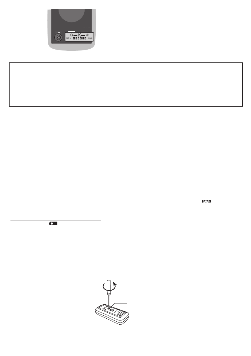
e.Avantd'inséreruntransistorsurl'adaptateur,vériez
toujoursquetouslescâblesdetestontétéretirésde
l'appareil.
f. Déposezlescâblesdetestdel'appareilavantd'ouvrir
lecouvercleducompartimentbatteriesouleboîtier.
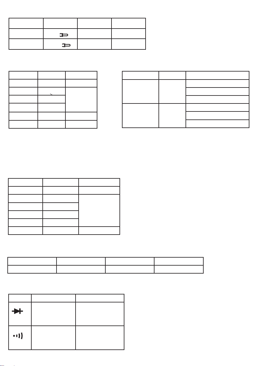
Symboles
CA (courant alternatif)
CC (courant continu)
Courant continu et alternatif
Information de sécurité importante. Consultez le manuel.
Présence de tension dangereuse possible. Prudence recommandée.
Mise à la terre
Fusible
Conforme aux Directives européennes
L'équipement est protégé par une double isolation ou par une isolation renforcée.
Batterie faible
Diode
Lavaleurmaximaleestgée.
Lesdonnéesafchéessontgées.

Fahrenheit
Centigrade
Test de continuité
Mesure avec pince (optionnel), permettant d'élargir le champ d'application de l'appareil.
Autorange (gamme automatique)
Cet appareil est conforme aux dispositions de la norme CAN/CSA-C22.2 NO. 61010-1, deuxième édition,
Amendement 1, ou à la version supérieure de la même norme, traitant le même niveau d'exigence de test.
ENTRETIEN
Pour garantir la protection contre les risques d'incendie, remplacez un fusible fondu uniquement par un fusible neuf de même
type.
Nettoyez l'appareil à l'aide d'un chiffon humide imbibé de savon doux. N'utilisez pas de produits abrasifs ni de solvants.
INTRODUCTION
Ce multimètre série est un appareil compact avec écran numérique 3,5 pouces pour mesurer des tensions CC et CA, des
courants CC et CA, des résistances, des diodes, des transistors, des continuités, des condensateurs.
Il est équipé d'une fonction d'indication de la polarité, de maintien des données, de mode MAX, d'indication de dépassement
de gamme et d'extinction automatique. Il offre une grande facilité d'utilisation et constitue un instrument idéal. Sauf indication
contraire, les instructions de ce manuel s'appliquent à tous les modèles de ces multimètres série.
STRUCTURE
1. Afchage
EcranLCD3,5pouces,pouvantafcherjusqu'à1999.
2. Bouton ʺRANGEʺ
Permet de basculer du mode gamme automatique au mode gamme
manuelle et de sélectionner la gamme manuelle désirée.
3. Bouton ʺFUNC.ʺ
Permet de sélectionner :
a. Des mesures de courant CC et CA.
b. Des mesures en Celsius et en Fahrenheit.
c. Des fonctions de test diode et de continuité.
4. Interrupteur
Permet d'allumer et d'éteindre l'appareil.
5. Sélecteur Fonction/Gamme
Permet de sélectionner la fonction et la gamme désirées.
6. Connecteur ʺ10Aʺ
Connecteurpourlebranchementducâbledetestrougepourlesmesuresdecourant
(de 200 mA à 10 A).
7. Connecteur ʺCOMʺ
Connecteurpourlebranchementducâbledetestnoir.
8. Connecteur ʺINPUTʺ
Connecteurpourlebranchementducâbledetestrougepourtouteslesmesures,àl'exceptiondesmesuresdecourant
(≥200mA).
9. Bouton ʺ ʺ
Pour activer ou désactiver le rétro-éclairage, appuyez sur ce bouton et maintenez la pression pendant environ 2 secondes.
Le rétro-éclairage s'éteint automatiquement environ 15 secondes après l'avoir activé.
10.Bouton ʺ ʺ
Permet d'entrer et de quitter le mode maintien des données.
11. Bouton " ʺ. Permet les enregistrements MAX.
SPECIFICATIONS GENERALES
Afchage : EcranLCD,afchagejusqu'à1999,rafraîchissement2-3fois/sec
Dépassement de gamme : ʺOLʺs'afcheàl'écran
Batterie : 3 piles 1,5 V AAA ou équivalent
Polarité négative : lesignenégatif"-ʺs'afcheautomatiquementàl'écran
Indication de batterie faible : ʺʺs'afcheàl'écran
Température d'utilisation : de0°Cà40°C,HR<75%
Température de stockage : de-10°Cà50°C,HR<85%
Dimensions : 158X75X35mm
Poids : environ 200 g (piles comprises)
FIG. 1

CARACTÉRISTIQUES
Laprécisionestassuréependantunepériodedeunanaprèsl'étalonnage,pouruneutilisationcomprisede18°Cà28°C,
avecunehumiditérelative<75%.
Laprécisionestde:±([%delavaleurafchée]+[nombredechiffreslesmoinssignicatifs]).
Gamme Résolution Précision
2 V 0,001 V ±(1.0%+5)
20 V 0,01 V
200 V 0,1 V
250 V 1 V ±(1.2%+5)
Gamme Résolution Précision
200 mV 0,1 mV ±(0.8%+5)
2 V 0,01 V
20 V 0,01 V
200 V 0,1 V
250 V 1 V ±(1%+5) Impédance d'entrée :10MΩ
Gamme de fréquence : de 40 Hz à 400 Hz
Protection contre les surcharges : 250 Vcc/ca eff
Réponse : moyenne, calibrée en fonction de la valeur rms de
l'onde sinusoïdale
Tension d'entrée max. : 250 Vca eff
Gamme Résolution Précision
200µA 0.1µA ±(1.2%+5)
2000µA 1µA
20 mA 0,01 mA
200 mA 0,1 mA
2 A 0,001 A ±{2.0%+10}
10 A 0,01 A
Protection contre les surcharges :
gammes µA et mA : Fusible F 250 mA/250 V
Gammes A : Fusible F 10A/250 V
Courant d'entrée max. :
Connecteur «INPUT» : 200 mA
Connecteur «10A» : 10 A
(Pourdesmesures<2A:durée<15secondes,
intervalle > 15 minutes)
Chute de tension :
200gammes µA, 20 mA et 2 A : 20 mV
2000gammes µA, 200 mA et 10 A : 200 mV
Gamme Résolution Précision
200µA 0.1µA ±(1.5%+5)
2000µA 1µA
20 mA 0,01 mA
200 mA 0,1 mA
2 A 0,001 A ±{3.0%+10}
10 A 0,01 A
Protection contre les surcharges :
gammes µA et mA : Fusible F 250 mA/250 V
Gammes A : Fusible F 10A/250 V
Courant d'entrée max. :
Connecteur «INPUT» : 200 mA
Connecteur «10A» : 10 A
(Pourdesmesures>2A:durée<15secondes,
intervalle > 15 minutes)
Chute de tension :
200gammes µA, 20mA et 2A : 20 mV
2000gammes µA, 200 mA et 10 A : 200 mV
Gamme de fréquence : de 40 Hz à 400 Hz
Réponse:moyenne,calibréeenfonctiondelavaleurrmsde
l'onde sinusoïdale
Gamme Résolution Précision
appareil 200A 0,1m V/0,1 A ±(1.2%+5)
appareil 1000 A 1 mV/1 A ±(1.2%+5)
Tension d'entrée max. : 200 mV
Courant CC (avec pince)
Courant CA
Courant CC
Tension CC
Impédance d'entrée :10MΩ
Protection contre les surcharges :
250 Vcc/ca eff
Tension d'entrée max. : 250 Vcc
Tension CA

Gamme Résolution Précision
200Ω 0,1Ω ±(1.2%+5)
2kΩ 0,001kΩ ±(1%+5)
20kΩ 0,01kΩ
200kΩ 0,1kΩ
2MΩ 0,001MΩ ±(1.2%+5)
20MΩ 0,01MΩ ±(1.5%+5)
Résistance
Tension circuit ouvert : environ 0,25 V
Protection contre les surcharges : 250 Vcc/
ca eff
Température (°C, °F)
Gamme Résolution Précision
de -20°C à
1000°C
1°C de-20°Cà0°C±(5%+4)
de0°Cà400°C±(1%+3)
de400°Cà1000°C±(2%+3)
de0°Fà1800°F 1°F de0°Fà50°F:±(5%+8)
de50°Fà750°F:±(1%-+6)
de750°Fà1800°F:±(2%+6)
Nota :
1. La précision ne tient pas compte de la sonde à thermocouple.
2. Les données de précision supposent une température am-
biantestableà±1°C.Encasdemodicationdelatempérature
ambiante de l'ordre de ±5°C, la précision nominale s'applique au
bout d'une heure.
Capacité
Gamme Résolution Précision
20 nF 0,01 nF ±(8%+10)
20 nF 0,1 nF ±(5%+5)
2µF 0.001µF
20µF 0.01µF
200µF 0.1µF
1000µF 1µF ±(8%+10)
Protection contre les surcharges :
200gammes µF et 1000µF : pas de protection contre les
surcharges
Autres gammes : Fusible F 250 mA/250 V
Tension circuit ouvert :
environ 0,5 V
Test hFE du transistor
Gamme hFE Courant de test Tension de test
PNP et NPN 0 ~ 1000 lb≈2µA Vcc≈1V
Gamme Description Observation
La
chute de tension
approximative
s'afche.
Tension circuit ouvert :
environ 1,5 V
Si la résistance est
inférieure à environ
30Ω,lebuzzer
intégré émet un bip.
Tension circuit ouvert :
environ 0,5 V
Diode et continuité
Protection contre les surcharges : 250 Vcc/ca eff
Pour le test de continuité :
Silarésistanceestcompriseentre30Ωet100Ω,
le buzzer peut retentir ou pas. Si la résistance est
supérieureà100Ω,lebuzzerneretentitpas.
Gamme Résolution Précision
appareil 200 A 0,1m V/0,1 A ±(1.5%+5)
appareil 1000 A 1 m V/1 A ±(1.5%+5)
Tension d'entrée max. : 200 mV
Gamme de fréquence : de 40 Hz à 400 Hz
Réponse :moyenne, calibrée en fonction de la
valeur rms de l'onde sinusoïdale
Courant CA (avec pince)

NOTICE D'UTILISATION
Mode maintien des données
Appuyez sur le bouton ʺʺ pourgerlavaleurafchée,l'indication" "s'afcheàl'écran.
Pourquitterlemodemaintiendesdonnées,ilvoussuftd'appuyerdenouveausurlebouton.Lesymbole" "disparaît.
Gamme manuelle et gamme automatique
Par défaut, l'appareil est réglé en mode gamme automatique pour les fonctions de mesure qui disposent du mode gamme
automatique et mode gamme manuelle. Lorsque l'appareil est réglé en mode gamme automatique, l'indication "AUTO" est
afchée.
1. Appuyez sur le bouton "RANGEʺpourpasserenmodegammemanuelle.L'indication"AUTO"disparaît.
Chaque pression sur le bouton "RANGEʺ augmente la gamme. Lorsque la gamme la plus élevée est atteinte, l'appareil
repasse à la gamme la plus basse.
2. Pour quitter le mode gamme manuelle, appuyez et maintenez la pression sur le bouton "RANGEʺ pendant environ 2
secondes.L'appareilrepasseenmodegammeautomatiqueetlesymbole"AUTOʺs'afche.
Mode MAX
Appuyez sur le bouton " ʺ pour passer au mode MAX, l'indication " "s'afche.Danscemode,
l'écranafchelavaleurmaximaleparmitouteslesmesureseffectuéesdepuisl'activationdecemode.Pourquittercemode,il
voussuftd'appuyerdenouveausurlebouton" ʺ, le symbole " ʺdisparaît.
Nota :
Le mode MAX n'est pas disponible dans certaines fonctions.
Mesure de tension CC ou CA
1.Connectezlecâbledetestnoirsurleconnecteur"COMʺetlecâbledetestrougesurleconnecteur"INPUT".
2. Placez le sélecteur de gamme sur la position pour les mesures de tension cc ou sur la position pour les mesures
de tension ca.
3. Sélectionnez le mode gamme automatique ou le mode gamme manuelle à l'aide du bouton ʺRANGE".
En mode gamme manuelle, si vous ne connaissez pas à l'avance l'échelle de tension à mesurer, sélectionnez d'abord la
gamme la plus élevée puis descendez de gamme en gamme jusqu'à obtenir une résolution satisfaisante.
4.Appliquezlescâblesdetestsurlasourceoulecircuitàmesurer.
5.Lisezlavaleurafchée.PourlesmesuresdetensionCC,lapolaritéducâbledetestrougeestindiquéeégalement.
Nota :
1.Dansunegammebasse,ilestpossiblequelavaleurafchéeparl'appareilsoitinstablelorsquelescâblesdetestn'ont
pas été connectés au circuit à mesurer. C'est normal et cela n'aura aucun impact sur la mesure.
2.Enmodegammemanuelle,lorsquel'indication"OLʺs'afche,celasigniequevousdevezsélectionnerunegamme
supérieure.
3. Pour éviter d'endommager l'appareil, la tension mesurée ne doit pas être supérieure à 250 Vcc/ca.
Mesure de courant CC ou CA
1.Connectezlecâbledetestnoirsurleconnecteur"COM".Silecourantàmesurerestinférieurà200mA,connectezle
câbledetestrougeauconnecteur"INPUT".Silecourantestcomprisentre200mAet10A,connectezlecâbledetest
rouge au connecteur "10A".
2. Positionnez le sélecteur de gamme sur
µ
, ou sur .
3. Appuyez sur le bouton "FUNC." pour sélectionner la mesure de courant CC ou CA, le symbole correspondant
s'afche.
4. Sélectionnez le mode gamme automatique ou le mode gamme manuelle à l'aide du bouton "RANGEʺ.
5. Coupez l'alimentation du circuit que vous souhaitez mesurer. Déchargez tous les condensateurs haute tension.
6.Ouvrezlecircuitàmesurer,connectezlescâblesdetestensérieaveclecircuit.
7.Remettezlecircuitentensionpuislisezlamesure.PourlesmesuresdecourantCC,lapolaritéducâbledetestrouge
est également indiquée.
Nota :
1. Si vous ne connaissez pas à l'avance l'échelle de courant à mesurer, sélectionnez d'abord la gamme la plus élevée puis
descendez de gamme en gamme jusqu'à obtenir une résolution satisfaisante.
2.Lorsquel'indicationdedépassementdegamme"OL"s'afche,celasigniequevousdevezsélectionnerunegamme
supérieure.
Mesure de courant
1. Pour mesurer un courant CC, vous devez utiliser la pince CC. Pour mesurer un courant CA, vous devez utiliser la pince CA.
2.Connectezlecâblenégatif(-)desortiedelapincesélectionnéesurleconnecteur"COMʺ,connectezlecâblepositif(+)de
sortiedelapincesurleconnecteur"INPUTʺ.
3. Placez le sélecteur de gamme sur la position .
4. Sélectionnez une mesure de courant CC ou de courant CA à l’aide du bouton "FUNC.ʺ.
5. Sélectionnez le mode gamme automatique ou le mode gamme manuelle à l’aide du bouton "RANGEʺ.
En mode gamme manuelle, si vous ne connaissez pas à l’avance l’échelle de courant à mesurer, sélectionnez d’abord la
gamme la plus élevée.

6. Serrez le circuit à mesurer avec la pince.
Nota :Vousnepouvezmesurerqu'uncâbleàlafoisetildoitêtrecentréaumilieudesmâchoiresdelapince.
7.Lisezlavaleurafchée.PourlesmesuresdecourantCC,lapolaritéducâbledetestpositif(+)delapinceest
également indiquée.
Nota :
1.Enmodegammemanuelle,lorsquel'indication"OL"s'afche,celasigniequevousdevezsélectionnerunegamme
supérieure.
2. Ne touchez pas le circuit testé avec vos mains ou votre peau.
3. Problème de concordance entre l'appareil et la sensibilité de la pince :
a. La sensibilité de la pince adaptée est de 0,1 A/0,1 mV. Si vous utilisez une pince adaptée, la valeur indiquée est la même
que la valeur mesurée.
b.Sivousutilisezunepincedontlasensibilitén'estpaségaleà0,1A/0,1mV,vousdevrezmultiplierlavaleurafchéepar
un facteur qui est fonction de la pince utilisée pour obtenir un résultat égal à la valeur mesurée.
Pour déterminer ce facteur, veuillez consulter la notice de la pince que vous utilisez.
Mesure de résistance
1.Connectezlecâbledetestnoirsurleconnecteur"COM"etlecâbledetestrougesurleconnecteur"INPUTʺ.
2. Positionnez le sélecteur sur la gamme Ω.
3.Sélectionnezlemodegammeautomatiqueoulemodegammemanuelleàl'aideduboutonʺRANGEʺ.
4.Appliquezlescâblesdetestsurlachargeàmesurer.Lisezlavaleurafchée.
Nota :
1.Pourlesmesuresderésistance>1MΩ,plusieurssecondespeuventêtrenécessairespourquelamesuresestabilise.
C'est normal pour les mesures de résistance élevée.
2.Lorsquel'entréen'estpasconnectée,c'est-à-direencasdecircuitouvert,lesymbole"OL"quis'afcheindiqueun
dépassement de gamme.
3. Avant de mesurer la résistance d'un circuit, assurez-vous que le circuit est hors tension et que tous les condensateurs ont
été complètement déchargés.
4.Enmodegammemanuelle,lorsquel'indicationdedépassementdegamme"OLʺs'afche,celasigniequevousdevez
sélectionner une gamme supérieure.
Mesure de capacité
1.Connectezlecâbledetestnoirsurleconnecteur"COMʺetlecâbledetestrougesurleconnecteur"INPUTʺ.
2. Positionnez le sélecteur sur la gamme souhaitée "1000µF","20µFʺ ou "nFʺ.
3.Sélectionnezlemodegammeautomatiqueoulemodegammemanuelleàl'aidedubouton"RANGEʺ.
4.Appliquezlescâblesdetestsurlecondensateuràmesurer.Assurez-vousquelapolaritéducondensateurestrespectée.
(Lecâbledetestrougedoitêtreconnectésurl'anodeducondensateurtandisquelecâbledetestnoirdoitêtreconnecté
sur la cathode du condensateur).
5.Lisezlavaleurafchée.
Nota :
Dansunegammebasse,ilestpossiblequ'unevaleurs'afcheavantlaconnexiondescâblesdetestsurlecondensateur.
C'estnormal:cettevaleurcorrespondàlacapacitérésiduelledescâblesdetestetducircuitd'entréedel'appareil;cela
n'altère pas la précision de la mesure.
Test de continuité
1.Connectezlecâbledetestnoirsurleconnecteur"COMʺetlecâbledetestrougesurleconnecteur"INPUTʺ.
2. Placez le sélecteur de gamme sur la position .
3. Appuyez sur le bouton "FUNC."jusqu'àcequelesymboleʺ ʺs'afche.
4.Connectezlescâblesdetestsurlecircuitàmesurer.
5.Silarésistanceestinférieureàenviron30Ω,lebuzzerintégréémetunbip.
Nota :
Avant d'effectuer le test, déconnectez l'alimentation du circuit à tester et déchargez complètement tous les condensateurs.
Test de diode
1.Connectezlecâbledetestnoirsurleconnecteur"COM"etlecâbledetestrougesurleconnecteur"INPUT"(Nota:La
polaritéducâbledetestrougeestpositive"+ʺ).
2. Placez le sélecteur de gamme sur la position .
3. Appuyez sur le bouton "FUNC.ʺjusqu’àcequelesymboleʺ ʺs’afche.
4.Connectezlecâbledetestrougesurl’anodedeladiodeàtesteretlecâbledetestnoirsurlacathodedeladiode.
5.
Lachutedetensiondirecteapproximativedeladiodes’afche.Encasd’inversiondesconnexions,l’indication"OL"s’afche.
Test du transistor
1. Placez le sélecteur de gamme sur la position hFE.
2. Voir la Figure 2, connectez l’adaptateur sur le connecteur "COM" et sur le connecteur "INPUT". N’inversez pas les
connexions.
3.DéterminezsiletransistorestdetypeNPNouPNP,identiezlescâblesdel’émetteurlocal,delabaseetducollecteur.
Introduisezlescâblesdutransistoràtesterdanslesoricesdelachedetestdel’adaptateur.
4. La valeur hFEapproximatives’afche.

Mesure de température
Nota
Pour éviter d'endommager l'appareil ou tout autre équipement, gardez en mémoire que lorsque l'appareil est
calibré pour des températures de -20°C à +1000°C et de 0°F à 1800°F, le thermocouple de type K fourni avec
l'appareil est calibré à 250°C. Lorsque les températures se trouvent en dehors de cette plage de calibrage, utilisez
un thermocouple à calibrage plus élevé.
Le thermocouple de type K est fourni en cadeau avec l'appareil, ce n'est pas un outil professionnel : vous ne
pouvez l'utiliser que pour effectuer des mesures non critiques. Pour des mesures précises, utilisez un
thermocouple professionnel.
1. Positionnez le sélecteur sur la gamme Temp.
2. Appuyez sur le bouton "FUNC." pour sélectionner une mesure en Celsius ou en Fahrenheit.
3.Introduisezlachenoire(ou"-")duthermocoupledetypeKdansleconnecteur"COM"etlacherouge(ou"+")du
thermocoupledansleconnecteur"INPUTʺ.
4. Appliquez doucement la pointe du thermocouple sur l'objet à mesurer.
5.Patientezuninstant,jusqu'àcequelamesures'afche.
1. Détection de tension CA
1. Placez le sélecteur de gamme sur la position ʺTEST" et éteignez l'appareil.
2. Déplacez le haut de l'appareil vers l'objet à détecter. Si l'appareil détecte une tension CA, le buzzer intégré retentit
et l'indicateur de détection CA s'allume.
2. Détection de ligne CA sous tension
1. Placez le sélecteur de gamme sur la position "TEST" et éteignez l'appareil.
2.Connectezuncâbledetestsurleconnecteur"INPUT",appliquezlasondedececâbledetestsurleconducteurdela
ligne à tester. Si la ligne est une ligne CA sous tension, le buzzer intégré retentit et l'indicateur de détection CA s'allume.
Extinction automatique
Sivousn'utilisezpasl'appareilpendantenviron15minutes,ils'éteintautomatiquement.Pourlerallumer,ilvoussuftde
tournerlesélecteurdegammeoud'appuyersurn'importequelbouton.Sivousappuyezsurleboutonʺ " pour rallumer
l'appareil après son extinction automatique, la fonction d'extinction automatique sera désactivée.
REMPLACEMENT DE LA BATTERIE
Lorsque le symbole " "s'afche,celasigniequelespilessontfaiblesetqu'ellesdoiventêtreremplacées.Pour
remplacerlespiles,utilisezuntournevisadaptépourtournerde90°danslesensindiquélavisdeblocageducouvercledu
compartiment batterie (voir la Figure 3). Déposez le couvercle du compartiment batterie et remplacez les piles usées par des
neuves du même type («AAA»).
Reposezlecouvercleducompartimentbatterieettournezlavisdeblocagede90°danslesenshorairepourverrouillerle
couvercle du compartiment batterie.
Nota :
N’appliquez pas de force excessive qui pourrait endommager la vis de blocage. N’utilisez pas un tournevis trop petit.
Prise de test du transistor
Fig. 2
Fig. 3
Pour ouvrir le couvercle du compartiment batterie
Vis de blocage

REMPLACEMENT DU FUSIBLE
Le fusible n'a que rarement besoin d'être remplacé et presque toujours à la suite d'une erreur de l'utilisateur de l'appareil.
Pour remplacer le fusible F 250mA/250V, ouvrez le couvercle du compartiment batterie, remplacez le fusible fondu par un
fusible neuf du même type.
Reposezlecouvercleducompartimentbatterieetverrouillez-le.
Pour remplacer le fusible F 10A/250V, déposez les vis du couvercle arrière et retirez-le, remplacez le fusible fondu par un
fusibleneufdumêmetype.Reposezlecouverclearrièreetrevissezlesvis.
Cet appareil utilise deux fusibles :
F1 : F 250mA/250V, Ø5x20mm
F2 : F 10A/250V, Ø5x20mm
ACCESSOIRES
Manuel : 1 exemplaire
Câbledetest: 1paire
ThermocoupledetypeK: 1article
Adaptateur : 1 article
Pince CC (en option)
Pince CA (en option)
NOTA :
1. Notre compagnie décline toute responsabilité en cas de perte.
2.Lecontenudecemanuelnepermetpasd'utiliserl'appareilpouruneapplicationspécique.
ELIMINATION DE CET ARTICLE
Cher client,
Si vous souhaitez vous débarrasser de cet article, n'oubliez pas que la plupart de ses composants
peuvent être valorisés et recyclés.
Ne le jetez pas avec les ordures ménagères, mais interrogez votre municipalité qui vous indiquera les sites de
récupération de votre région.

EN WARNING
IMPORTANT SAFETY INFORMATION ENCLOSED.
READ THIS MANUAL BEFORE OPERATING THE MACHINE.
IT IS THE RESPONSIBILITY OF THE EMPLOYER TO PLACE THE INFORMATION IN THIS MANUAL
INTO THE HANDS OF THE OPERATOR.
FAILURE TO OBSERVE THE FOLLOWING WARNINGS COULD RESULT IN INJURY.
SAFETY INFORMATION
This series digital multimeters have been designed
according to IEC-61010 concerning electronic measuring
instruments with a measurement category (CAT Il 250V)
and pollution degree 2.
Warning
To avoid possible electric shock or personal injury, follow
these guidelines:
a. Do not use the meter if it is damaged. Before you use
the meter, inspect the case. Pay particular attention to
the insulation surrounding the connectors.
b. lnspect the test leads for damaged insulation or
exposed metal.
Checkthetestleadsforcontinuity.Replacedamaged
test leads before you use the meter.
Do not use the test leads with other equipment.
c. Do not use the meter if it operates abnormally.
Protection may be impaired. When in doubt, have the
meter serviced.
d. Do not operate the meter around explosive gas, vapor,
or dust.
e. Do not apply more than the rated voltage, as marked on
the meter, between terminals or between any terminal
and earth ground.
f. Before use, verify the meter’s operation by measuring a
known voltage.
g. When measuring current, turn off circuit power before
connectingthemeterinthecircuit.Rememberto
place the meter in series with the circuit.
h.Whenservicingthemeter,useonlyspecied
replacement parts.
i. Use caution when working with voltage above
30V ac rms, 42V peak, or 60V dc. Such voltages pose
a shock hazard.
j.Whenusingtheprobes,keepyourngersbehindthe
ngerguardsontheprobes.
k. When making connections, connect the common test
lead before you connect the live test lead. When you
disconnecttestleads,disconnectthelivetestleadrst.
l.Removethetestleadsfromthemeterbeforeyouopen
the battery cover or the case.
m. Do not operate the meter with the battery cover or
portions of the case removed or loosened.
n. To avoid false readings, which could lead to possible
electric shock or personal injury, replace the batteries
as soon as the low battery indicator ( ) appears.
o. To avoid electric shock, don’t touch any naked
conductor with hand or skin.
p.Remainingendangerment
When an input terminal is connected to dangerous live
potentiel, it is to be noted that this potential at all other
terminals can occur!
q. CAT Il - Measurement category Il is for measurements
performed on circuits directly connected to low voltage
installation.
(Examples are measurements on household appliances,
portable tools and similar equipments.)
Do not use the meter for measurements within
Measurement Categories Ill and IV.
Caution
To avoid possible damage to the meter or to the
equipment under test, follow these guidelines:
a. Disconnect circuit power and discharge all capacitors
before lasting resistance, diode, continuity, temperature
or capacitor.
b. Use the proper tenminals, function, and range for your
measurements.
c. Before measuring current check the meter’s fuse and
turn off the power to the circuit before connecting the
meter to the circuit.
d. Before rotating the range switch to change functions,
remove the test leads or the clamp from the circuit
under test.
e. Before inserting transistor to the adapter, always be
sure all test leads have been removed from the mater.
f.Removetestleadsfromthemeterbeforeopeningthe
battery cover or the case.
Symbols
AC (alternating current)
DC (direct current)
Both direct and alternating current
Importantsafetyinformation.Refertothemanual.
Dangerous voltage may be present. Be cautious.
Earth ground
Fuse
Conforms to European Union directives
The equipment is protected throughout by double insulation or reinforced insulation.
Low battery
Diode
The maximum value is being held.
The display data is being held.

Fahrenheit
Centigrade
Continuity test
Measurementwithclamp(optional),wideningtheeldofapplicationsofthemeter
Autorange
This product has been to tested to the requirements of CAN/CSA-C22.2 NO. 61010-1, second edition, including
Amendement 1, or a later version of the same standard incorporating the same level of testing requirements.
MAINTENANCE
Tocontinueprotectionagainstre,replaceblownfuseonlywithanewoneofthesamerating.
To clean the meter, use a damp cloth and mild detergent only, do not use abrasives or solvents on it.
INTRODUCTION
This series multimeters are compact 3 1/2digits digital multimeters for measuring DC and AC voltage, DC and AC current,
resistance, temperature, diode, transistor, continuity, capacitance.
They feature polarity indication, data hold, MAX mode, overrange indication and automatic power-off. They are easy to
operate and are ideal instrument tools. Except where noted, the instructions in this manual apply to all models of this series
multimeters.
STRUCTURE
1. Display
31/2digitLCD,wilhamax.readingof1999
2. ʺRANGEʺ Button
Used to swilch between autorange mode and manual range
mode as weil as to select desired manual range.
3. "FUNC." Button
Used to switch the meter between:
a. DC current and AC current measurements.
b. Celsius and Fahrenheit measurements.
c. Diode and continuity test functions.
4. Power Switch
Used to turn on/off the meter.
5. Function/Range Switch
Used to select desired function and range.
6. ʺ10Aʺ Jack
Plug-in connector for the red test lead for current ( 200mA~10A) measurements.
7. ʺCOMʺ Jack
Plug-in connector for the black test lead.
8. "INPUTʺ Jack
Plug-in connector for the red test lead for all measurements except current
(≥200mA)measurements.
9. " ʺ Button
To turn on or off the backlight, press and hold this button for about 2 seconds.
The backlight will turns off automatically about 15 seconds later after you turn on it.
10.ʺ ʺ Button
Used to enter/exit Data hold mode.
11. "ʺButton. Used for MAX recording.
GENERAL SPECIFICATION
Display: LCD,1999counts,updates2-3times/sec
Overrange Indication: ʺOLʺshownonthedisplay
Battery: 1.5V, AAA or equivalent, 3 pieces
Negative Polarity Indication: negativesign"-ʺshownonthedisplayautomatically
Low Battery Indication: ʺʺshown on the display
Operating Temperature: 0°Cto40°C,<75%RH
Storage Temperature: -10°Cto50°C,<85%RH
Dimensions: 158X75X35mm
Weight: about 200g (including batteries)
FIG. 1

SPECIFICATIONS
Accuracyisspeciedforaperiodofoneyearaftercalibrationandat18°Cto28°C,withrelativehumidity<75%.
Accuracyspecicationstaketheformof:±([%ofReadlng]+[numberofLeastSignicantDigits])
Range Resolution Accuracy
2V 0.001V ±(1.0%+5)
20V 0.01V
200V 0.1V
250V 1V ±(1.2%+5)
Range Resolution Accuracy
200mV 0.1mV ±(0.8%+5)
2V 0.01V
20V 0.01V
200V 0.1V
250V 1V ±(1%+5) Input Impedance:10MΩ
Frequency Range: 40Hz ~ 400Hz
Overload Protection: 250V DC/AC rms
Response: Average, calibrated in rms of sine wave
Max. Input Voltage: 250V AC rms
Range Resolution Accuracy
200µA 0.1µA ±(1.2%+5)
2000µA 1µA
20mA 0.01mA
200mA 0.1mA
2A 0.001A ±{2.0%+10}
10A 0.01A
Overload Protection:
µA
and mA ranges: F 250mA/250V fuse
A ranges: F 10A/250V fuse
Max. Input Current:
«INPUT» jack : 200mA
«10A» jack: 10A
(Formeasurements>2A:duration<15seconds,
interval > 15 minutes )
Voltage Drop:
200µA, 20mA and 2A ranges: 20mV
2000µA, 200mA and 10A ranges: 200mV
Range Resolution Accuracy
200µA 0.1µA ±(1.5%+5)
2000µA 1µA
20mA 0.01mA
200mA 0.1mA
2A 0.001A ±{3.0%+10}
10A 0.01A
Overload Protection:
µA
and mA ranges: F 250mA/250V fuse
A ranges: F 10A/250V fuse
Max. Input Current:
«INPUT» jack : 200mA
«10A» jack: 10A
(Formeasurements>2A:duration<15seconds,
interval > 15 minutes )
Voltage Drop:
200µA, 20mA and 2A ranges: 20mV
2000µA, 200mA and 10A ranges: 200mV
Frequency Range: 40Hz ~400Hz
Response:Average,calibratedinrmsofsinewave
Range Resolution Accuracy
meter 200A 0.1mV/0.1A ±(1.2%+5)
meter 1000A 1mV/1A ±(1.2%+5)
Max. Input Voltage: 200mV
DC Current (with clamp)
AC Current
DC Current
DC Voltage
Input Impedance:10MΩ
Overload Protection: 250V DC/AC rms
Max. Input Voltage: 250V DC
AC Voltage

Range Resolution Accuracy
200Ω 0,1Ω ±(1.2%+5)
2kΩ 0.001KΩ ±(1%+5)
20kΩ 0.01KΩ
200kΩ 0.1KΩ
2MΩ 0.001MΩ ±(1.2%+5)
20MΩ 0.01MΩ ±(1.5%+5)
Resistance
Open Circuit Voltage: about 0.25V
Overload Protection: 250V DC/AC rms
Temperature (°C, °F)
Range Resolution Accuracy
-20°C ~ 1000°C 1°C -20°C~0°C±(5%+4)
0°C~400°C±(1%+3)
400°C~1000°C±(2%+3)
0°F~1800°F 1°F 0°F~50°F:±(5%+8)
50°F~750°F:±(1%-+6)
750°F~1800°F:±(2%+6)
Note:
1. Accuracy does not include error of the thermocouple probe.
2.Accuracyspecicationassumesambienltemperatureisstable
to ±1°C. For ambient temperature changes of ±5°C, rated
accuracy applies after 1 hour.
Capacitance
Range Resolution Accuracy
20nF 0.01nF ±(8%+10)
20nF 0.1nF ±(5%+5)
2µF 0.001µF
20µF 0.01µF
200µF 0.1µF
1000µF 1µF ±(8%+10)
Overload Protection:
200µF and 1000µF ranges: no overload protection
the other ranges: F 250mA/250V fuse
Open Circuit Voltage:
about 0.5V
Transistor hFE Test
Range hFE Test Current Test Voltage
PNP & NPN 0 ~ 1000 lb≈2µA Vce≈1V
Range Description Remark
The approx. forward
voltage drop will be
displayed.
Open Circuit Voltage:
about 1.5V
The built-in buzzer
will sound if the
resistance is less
thanabout30Ω.
Open Circuit Voltage:
about 0.5V
Diode and Continuity
Overload Protection: 250V DC/AC rms
For Continuity test :
Iftheresistanceisbelween30Ωand100Ω,thebuz-
zer may sound or may not sound. If the resistance
ismorethan100Ω,thebuzzerwon’tsound.
Range Resolution Accuracy
meter 200A 0.1mV/0.1A ±(1.5%+5)
meter 1000A 1mV/1A ±(1.5%+5)
Max. Input Voltage: 200mV
Frequency Range: 40Hz ~ 400Hz
Response: Average, calibrated in rms of sine wave
AC Current (with clamp)

OPERATION INSTRUCTION
Data Hold Mode
Press the ʺʺ Button to hold the present reading on the display, the symbol " " will appear on the display as an
indicator.
To exit the Data Hold mode, just press this button again " " disappears.
Manual Ranging and Autoranging
The meter defaults to autorange mode in measurement functions which have both autorange mode and manual range mode.
When the meter is in the autorange mode, "AUTO" is displayed.
1. Press the "RANGEʺ button to enter the manual range mode "AUTO" disappears.
Each press of the "RANGEʺ button increments the range. When the highest range is reached, the meter wraps to the
lowest range.
2. To exit the manual range mode, press and hold down the "RANGEʺ button for about 2 seconds. The meter returns to the
autorangemodeandthesymbol"AUTOʺisdisplayed.
MAX Mode
Press the " ʺ Button to enter the MAX mode, the symbol " " will appear on the display as an indicator. ln this mode,
the display shows the maximum reading of all readings taken since this mode is activated. To exit the mode, just press the
"ʺbutton again," ʺwilldisappear.
Note:
ln some functions, the MAX mode is not available.
Measuring DC or AC Voltage
1.Connecttheblacktestleadtothe"COMʺjackandtheredtestleadtothe"INPUT"jack.
2. Set the range switch to the position for dc voltage measurements or to the position for ac voltage measurements.
3. Select auto range or manual range mode with the ʺRANGE" button.
ln manual range mode, if the magnitude of the voltage to be measured is not known beforehand, select the highest range
rstandthenreduceitrangebyrangeuntilsatisfactoryresolutionisobtained.
4. Connect the test leads across the source or circuit to be measured.
5.Readthereadingonthedisplay.ForDCvoltagemeasurements,thepolarityoftheredtestleadconnectionwillbeindicated
as well.
Note:
1. ln a small range, the meter may display an unstable reading when the test leads have not been connected to the circuit to
be measured. lt is normal and will not affect measurement.
2.lnmanualrangemode,whenthemetershowstheoverrangeindicator"OLʺ,ahigherrangeshouldbeselected.
3. To avoid damage to the meter, don’t measure a voltage higher than 250V DC/AC.
Measuring DC or AC Current
1. Connect the black test lead to the "COM" jack. If the current to be measured is less than 200mA, connect the red test lead
to the "INPUT" jack. If the current is between 200mA and 10A, connect the red test lead to the "10A" jack instead.
2. Set the range switch
µ
, or range.
3. Press the "FUNC." button to select DC current or AC current measurement, the display will show the corresponding
symbol.
4. Select autorange or manual range mode with the "RANGEʺ button.
5. Tum off power to the circuit which you want to measure. Discharge all high voltage capacitors.
6. Break the circuit path to be measured, connect the test leads in series with the circuit.
7.Turnonpowertothecircuitandthenreadthedisplay.ForDCcurrentmeasurements,thepolarityofredleadconnection
will be indicated as well.
Note:
1. If the magnitude of the current to be measured is not known beforehand, select the highest range and then reduce it range
by range until satisfactcry resolution is obtained.
2. When the display shows the overrange indicator "OL", a higher range has to be selected.
Measuring Current
1. If you want to measure DC current, you must use the DC clamp. If you want to measure AC current, you must use the AC
clamp.
2.Connectthenegative(-)outputleadoftheselecteddamptothe"COMʺjack,connectthepositive(+)outputleadofthe
clamptothe"INPUTʺjack.
3. Set the range switch to position.
4. Select DC current or AC current measurement with the "FUNC.ʺbutton.
5. Select autorange or manual range mode with the "RANGEʺ button.
ln manual range mode, if the magnitude of the current to be measured is not known beforehand, select the highest range.
6. Clamp the circuit to be measured with the clamp.
Note: Each time only one cable should be clamped and the cable should be in the center of the clamp jaws.

7.Readthereadingonthedisplay.ForDCcurrentmeasurements,thepolarityofthepositive(+)outputleadoftheclampwill
be indicated as well.
Note:
1. ln manual range mode, when the display shows the overrange indicator "OL", a higher range should to be selected.
2. Don’t touch the circuit under test with hand or skin.
3. Matching problem about the meter and the sensitivity of the clamp:
a. The sensitivity of the matching damp is 0.1A/0.1mV. lf you use a matching clamp, the present indicated value is same
to the measured value.
b. If you use a clamp whose sensitivity does not equal 0.1A/0.1 mV, you should multiply the present reading by a factor
which is determined by the used clamp, the result is the measured value.
To determine the factor, please refer to the instruction of the clamp which you use.
Measuring Resistance
1.Connecttheblacktestleadtothe"COM"jackandtheredtestleadtothe"INPUTʺjack.
2. Set the range switch to Ωrange.
3.SelectautorangeormanualrangemodewilhtheʺRANGEʺbutton.
4.Connectthetestleadsacrosstheloadtobemeasured.Readthereadingonthedisplay.
Note:
1.Forresistancemeasurements>1MΩ,themetermaytakeafewsecondstostabilizereading.Thisisnormalforhigh-
resistance measurements.
2. When the input is not connected, i.e. at open circuit, the symbol "OL" will be displayed as an overrange indicator.
3. Before measuring in-circuit resistance, be sure that the circuit under test has all power removed and all capacitors have
been fully discharged.
4.lnmanualrangemode,whenthedisplayshowstheoverrangeindicator"OLʺ,ahigherrangehastobeselected.
Measuring Capacitance
1.Connecttheblacktestleadtothe"COMʺjackandtheredtestleadtolhe"INPUTʺjack.
2. Set the range switch to desired "1000µF","20µFʺ or "nFʺ position.
3.Selectautorangeormanualrangemodewilhthe"RANGEʺbutton.
4. Connect test leads across the capacitor to be measured. Make sure that the polarity of the capacitor is observed.
(The red test lead should be connected to the anode of the capacitor, and the black one should be connected to the
cathode of the capacitor.)
5.Readthereadingonthedisplay.
Note:
ln small range, before the test leads are connected to the capacitor, the display may show a reading. This is normal because
of the stray capacitance of the test leads and input circuit of the meter and will not affect the measurement accuracy.
Continuity Test
1.Connecttheblacktestleadtothe"COMʺjackandtheredtestleadtothe"INPUTʺjack.
2. Set the range switch to range.
3. Press the "FUNC." buttonuntilthesymbolʺ ʺappearsonthedisplay.
4. Connect the test leads across the circuit to be measured.
5.Iftheresistanceislowerthanabout30Ω,thebuilt-inbuzzerwillsound.
Note:
Before test, disconnect all power to the circuit to be tested and discharged all capacitors fully.
Diode Test
1. Connect the black test lead to the "COM" jack and the red test lead to the "INPUT" jack (Note: The polarity of the red test
leadispositive"+ʺ).
2. Set the range switch to range.
3. Press the "FUNC.ʺbuttonuntilthesymbolʺ ʺappearsonthedisplay.
4. Connect the red test lead to the anode of the diode to be tested and the black test lead to the cathode of the diode.
5. The display will show the approximate forward voltage drop of the diode. If the connections are reversed, "OL" will be
shown on the display.
Transistor Test
1. Set the range switch to hFE position.
2.RefertotheFigure2,connecttheadaptertothe"COM"jackandthe"INPUT"jack.Don’treversetheconnection.
3. ldentify whether the transistor is NPN or PNP type and locale emitter, base and collector leads. lnsert the leads of the
transistor to be tested into the proper holes of the transistor test socket of the adapter.
4. The display will show the approximate hFE value.

Measuring Temperature
Note
To avoid possible damage to the meter or other equipment, remember that while the meter is rated for -20°C to
+1000°C and 0°F to 1800°F, the K type Thermocouple provided with the meter is rated to 250°C. For temperatures
out of that range, use a higher rated thermocouple.
The K Type Thermocouple provided with the meter is a present, it is not professional and can only be used for
non-critical measurements. For accurate measurements, usa a professionnal thermocouple.
1. Set the range switch to Temp range.
2. Press the "FUNC." button to select celsius or fahrenheit measurement.
3.lnserttheblack(or"-")plugoftheKtypethermocoupletothe"COM"jackandthered(or"+")plugofthethermocoupleto
the"INPUTʺjack.
4. Carefully touch the sensing end of the thermocouple to the object to be measured.
5. Wait a while, then read the reading on the display.
1. AC Voltage Detection
1. Set the range switch to the ʺTEST" range position, and turn off the meter.
2. Move the top of the meter to the object to be detected. When the meter detects AC voltage, the built-in buzzer will sound
and the AC Detection lndicator will light.
2. To Detect AC Live Line
1. Set the range switch to the "TEST" position, and turn off the meter.
2. Connect a test lead to the "INPUT" jack, touch the probe of this test lead to the conductor of the line to be tested. If the
line is an ac live line, the built-in buzzer will sound and the AC Detection lndicator will light.
Auto Power Off
If you don’t operate the meter for about 15 minutes, it will turn off automatically. To turn on it again, just rotate the range switch
orpressabutton.Ifyoupresstheʺ " button to arouse the meter after it turns off automalically, the automatic power-off
feature will be disabled.
BATTERY REPLACEMENT
When the symbol " " appears on the display, the batteries are low and should be replaced. To replace the battery, use an
appropriatescrewdrivertogenllyrotatetherotarylockonthebatterycoverby90°intheindicateddirection(refertoFigure3).
Removethebatterycoverandreplacetheexhaustedbatterieswithnewbatteriesofthesametype(«AAA»type).
Reinstallthebatterycover,andgentlyrotatetherotarylockby90°clockwisetolockthebatterycover.
Note:
Excess force will cause damage to the rotary lock. Don’t use a screwdriver which is not big enough.
FUSE REPLACEMENT
Fuse rarely needs replacement and is blown almost always as a result of operator’s error.
To replace the F 250mA/250V fuse, open the batery cover, replace the blown fuse with a new one of the same rating.
Reinstallthebatterycoverandlockthiscover.
To replace the F 10A/250V fuse, remove the screws on the back cover and remove the back cover, replace the blown fuse
withanewoneofthesamerating.Reinstallthebackcoverandthescrews.
This meter uses two fuses:
F1: F 250mA/250V, Ø5x20mm
F2: F 10A/250V, Ø5x20mm
Transistor Test Socket
Fig. 2
Fig. 3 To open the battery cover
RotaryLock

ACCESSORIES
Manual: 1 piece
Test Lead: 1 pair
KTypeThermocouple: 1piece
Adapter: 1 piece
DC Clamp (optional)
AC Clamp (optional)
NOTE
1. Our company will not take the other responsibilities for any loss.
2. The contents of this manual can not be used as the reason to use the meter for special application.
DISPOSAL OF THIS ARTICLE
Dear Customer,
lf you at some point intend to dispose of this article, then please keep in mind that many of its components consist
of valuable materials, which can be recycled.
Please do not discharge it ln the garbage bin, but check with your local council for recycling facilities in your area.

DE ACHTUNG
NACHFOLGEND WICHTIGE SICHERHEITSHINWEISE.DIESE BETRIEBSANWEISUNG VOR INBETRIEB-
NAHME DIE MASCHINE UNBEDINGT LESEN. DER ARBEITGEBER IST VERPFLICHTET, DIE IN DIESEM
HANDBUCH GEGEBENEN INFORMATIONEN DEM BEDIENER ZUGÄNGLICH ZU MACHEN. DIE NICHTEIN-
HALTUNG DIESER WARNHINWEISE KANN ZU VERLETZUNGEN FÜHREN.
SICHERHEITSINFORMATIONEN
Die digitalen Universalmessgeräte dieser Baureihe
erfüllen die Norm IEC-61010 für elektronische Messins-
trumentemiteinerMesskategorie(KATIl250V)und
Verschmutzungsgrad 2.
Warnung
Zum Vermeiden möglicher Elektroschocks oder
KörperverletzungenbittedieseVorschriftenbefolgen:
a. Das Messgerät nicht benutzen, wenn es beschädigt
ist. Vor dem Benutzen des Messgeräts das Gehäuse
untersuchen. Der Isolierung um den Steckern
besondere Aufmerksamkeit schenken.
b. Die Prüfkabel auf beschädigte Isolierung oder blankes
Metall untersuchen.
Die Prüfkabel auf Durchgang kontrollieren. Beschädigte
Prüfkabel vor dem Benutzen des Messgeräts ersetzen.
Die Prüfkabel nicht mit anderen Geräten benutzen.
c. Das Messgerät nicht benutzen, wenn es anomal
funktioniert. Der Schutz kann beeinträchtigt sein. Das
Messgerät im Zweifelsfall warten lassen.
d. Das Messgerät nicht einsetzen, wenn es explosive
Gase, Dampf oder Staub gibt.
e. Nicht mehr als die auf dem Messgerät angegebene
Nennspannung zwischen den Buchsen oder zwischen
einer Buchse und der Erde aufbringen.
f. Vor der Benutzung den Betrieb des Messgeräts durch
Messen einer bekannten Spannung überprüfen.
g. Beim Messen von Strom, den Stromkreis erst
ausschalten, bevor das Messgerät an den Stromkreis
angeschlossen wird. Daran denken, das Messgerät in
ReihezumStromkreiszuschalten.
h. Beim Warten des Messgeräts nur angegebene
Ersatzteile benutzen.
i. Beim Arbeiten mit Spannungen über 30 V AC eff.,
42 V Spitze oder 60 V DC Vorsicht walten lassen. Bei
besagten Spannungen besteht Elektroschockgefahr.
j. Beim Benutzen der Messspitzen mit den Fingern hinter
dem Fingerschutz an den Messspitzen bleiben.
k. Beim Herstellen von Verbindungen erst das
gemeinsame Prüfkabel anschließen, bevor Sie das
stromführende Prüfkabel anschließen. Beim Abziehen
der Prüfkabel zuerst das stromführende Prüfkabel
abziehen.
l. Die Prüfkabel vom Messgerät entfernen, bevor Sie den
Batteriedeckel oder das Gehäuse öffnen.
m. Das Messgerät nicht benutzen, wenn der
Batteriedeckel oder Teile des Gehäuses entfernt oder
gelockert sind.
n. Zum Vermeiden von falschen Messungen, die
möglicherweisezuElektroschockoderKörperverletzun-
gen führen könnten, die Batterien ersetzen, sobald die
Batterie fast leer Anzeige ( ) erscheint.
o. Zum Vermeiden von Elektroschock, blanke Leiter nicht
mit der Hand oder Haut berühren.
p. Bleibende Gefährdung
Wenn eine Eingangsbuchse an eine gefährliche
Spannung angeschlossen wird, kann diese Spannung
an allen anderen Buchsen auftreten!
q. KAT Il - Die Messkategorie Il dient für Messungen
an Stromkreisen, die elektrisch über Stecker direkt mit
dem Niederspannungsnetz verbunden sind.
(Beispiele sind Messungen an Haushaltsgeräten,
tragbaren Elektrowerkzeugen und ähnlichen Geräten.)
Das Messgerät nicht für Messungen in den
Messkategorien III und IV benutzen.
Vorsicht
Um Schäden am Messgerät oder der geprüften Ausrüs-
tung zu vermeiden, bitte folgende Vorschriften befolgen:
a. Vor dem Prüfen von Widerstand, Diode, Durchgang,
TemperaturoderKondensatordenStromvom
StromkreisabtrennenundalleKondensatorenentladen.
b. Die richtigen Buchsen, die richtige Funktion und den
richtigen Bereich für Ihre Messungen benutzen.
c. Vor dem Messen von Strom die Sicherung des Mess-
geräts prüfen und den Stromkreis ausschalten, bevor das
Messgerät an den Stromkreis angeschlossen wird.
d. Vor dem Drehen des Bereichsschalters zum Wechseln
der Funktionen die Prüfkabel oder die Zange vom geprüf-
ten Stromkreis entfernen.
e. Vor dem Einsetzen eines Transistors in den Adapter
immer sicherstellen, dass alle Prüfkabel aus dem Mess-
gerät entfernt wurden.
f. Die Prüfkabel vom Messgerät entfernen, bevor Sie den
Batteriedeckel oder das Gehäuse öffnen.
Symbole
AC (Wechselstrom)
DC (Gleichstrom)
Sowohl Gleich- als auch Wechselstrom
Wichtige Sicherheitsinformationen. Siehe die Anleitung.
Es kann gefährliche Spannung anliegen. Seien Sie vorsichtig.
Erdung
Sicherung
ErfülltdieRichtlinienderEuropäischenUnion
Das Gerät ist durch doppelte Isolierung oder verstärkte Isolierung vollständig geschützt.
Batterie fast leer
Diode
Der maximale Wert wird gehalten.
Die angezeigten Daten werden gehalten.

Fahrenheit
Celsius
Durchgangsprüfung
Messung mit Zange (optional) für mehr Anwendungsmöglichkeiten des Messgeräts
Automatischer Messbereich
Dieses Produkt wurde gemäß CAN/CSA-C22.2 NO. 61010-1, zweite Ausgabe, einschließlich
Anhang 1 oder spätere Version derselben Norm mit denselben Prüfanforderungen geprüft.
WARTUNG
Für dauerhaften Brandschutz dürfen durchgebrannte Sicherungen nur durch neue Sicherungen derselben Stärke ersetzt
werden.
ZumReinigendesMessgerätsnureinfeuchtesTuchundeinmildesReinigungsmittelverwenden.KeineScheuer-oder
Lösungsmittel verwenden.
EINFÜHRUNG
Die Universalmessgeräte dieser Baureihe sind kompakte 3 1/2-stellige digitale Universalmessgeräte zum Messen von Gleich-
undWechselspannung,Gleich-undWechselstrom,Widerstand,Temperatur,Diode,Transistor,Durchgang,Kapazität.
Sie weisen die Funktionen Polaritätsangabe, Datenhaltemodus, MAX-Modus, Überbereichsangabe und automatische Abs-
chaltung auf. Sie sind leicht zu bedienen und ideale Messwerkzeuge. Wenn nicht anders angegeben, gelten die Anweisungen
in dieser Anleitung für alle Modelle dieser Baureihe.
AUFBAU
1. Display
31/2stelligesLCD-Displaymiteinermax.Anzeigevon1999
2. ʺRANGEʺ Taste
Zum Umschalten zwischen dem automatischen Messbereichsmodus
und dem manuellen Messbereichsmodus sowie zum Auswählen des
gewünschten manuellen Messbereichs.
3. "FUNC." Taste
Zum Umschalten des Messgeräts zwischen:
a. Gleichstrom- und Wechselstrommessungen.
b. Celsius- und Fahrenheit-Messungen.
c. Dioden- und Durchgangsprüffunktionen.
4. Ein-/Aus-Schalter
Zum Ein-/Ausschalten des Messgeräts.
5. Funktions-/Bereichsschalter
Zum Auswählen der gewünschten Funktion/des gewünschten Bereichs.
6. ʺ10 Aʺ Klinkenbuchse
Steckbuchse für das rote Prüfkabel für Strommessungen (200 mA~10 A).
7. ʺCOMʺ Klinkenbuchse
Steckbuchse für das schwarze Prüfkabel.
8. "INPUTʺ Klinkenbuchse
SteckbuchsefürdasrotePrüfkabelfüralleMessungenaußerStrommessungen(≥200mA).
9. " ʺ Taste
Zum Ein- oder Ausschalten der Hintergrundbeleuchtung diese Taste drücken und ca. 2 Sekunden lang halten.
Die Hintergrundbeleuchtung geht ca. 15 Sekunden nach dem Einschalten automatisch wieder aus.
10.ʺ ʺ Taste
Zum Aufrufen/Verlassen des Datenhaltemodus.
11. "ʺTaste. Für die MAX-Aufzeichnung.
ALLGEMEINE SPEZIFIKATION
Display: LCD,Zählerstandbis1999,wird2-3Mal/saktualisiert
Überbereichsangabe: ʺOLʺamDisplaygezeigt
Batterie: 1,5V, AAA oder gleichwertig, 3 Stück
Negative Polarität Angabe: AutomatischeAnzeigeeinesMinuszeichens("-ʺ)amDisplay
Batterie fast leer Anzeige ʺʺam Display gezeigt
Betriebstemperatur: 0°Cbis40°C,<75%RH
Lagerungstemperatur: -10°Cbis50°C,<85%RH
Abmessungen: 158X75X35mm
Gewicht: ungefähr 200 g (einschließlich Batterien)
ABB. 1

SPEZIFIKATIONEN
DieGenauigkeitgiltfüreinenZeitraumvoneinemJahrnachderKalibrierungundbei18°Cbis28°C,beieinerLuftfeuchtigkeit
von<75%.
DieGenauigkeitentsprichtfolgenderFormel:±([%derAnzeige]+[AnzahlderniederwertigenStellen])
Bereich Auösung Genauigkeit
2V 0,001V ±(1,0%+5)
20V 0,01V
200V 0,1V
250V 1V ±(1,2%+5)
Bereich Auösung Genauigkeit
200mV 0,1mV ±(0,8%+5)
2V 0,01V
20V 0,01V
200V 0,1V
250V 1V ±(1%+5) Eingangsimpedanz:10MΩ
Frequenzbereich: 40Hz ~ 400Hz
Überlastschutz: 250V DC/AC eff
Ansprechverhalten: Durchschnittlich, kalibriert in Sinuswelle
RMS
Max. Eingangsspannung: 250V AC eff
Bereich Auösung Genauigkeit
200µA 0,1µA ±(1,2%+5)
2000µA 1µA
20mA 0,01mA
200mA 0,1mA
2A 0,001A ±(2,0%+10)
10A 0,01A
Überlastschutz:
µA
und mA Bereiche: F 250mA/250V Sicherung
A Bereiche: F 10A/250V Sicherung
Max. Eingangsstrom:
"INPUT"Klinkenbuchse:200mA
"10A"Klinkenbuchse:10A
(FürMessungen>2A:Dauer<15Sekunden,
Intervall > 15 Minuten)
Spannungsabfall:
200µA, 20mA und 2A Bereiche: 20mV
2000µA, 200mA und 10A Bereiche: 200mV
Bereich Auösung Genauigkeit
200µA 0,1µA ±(1,5%+5)
2000µA 1µA
20mA 0,01mA
200mA 0,1mA
2A 0,001A ±(3,0%+10)
10A 0,01A
Überlastschutz:
µA
und mA Bereiche: F 250mA/250V Sicherung
A Bereiche: F 10A/250V Sicherung
Max. Eingangsstrom:
"INPUT"Klinkenbuchse:200mA
"10A"Klinkenbuchse:10A
(FürMessungen>2A:Dauer<15Sekunden,
Intervall > 15 Minuten)
Spannungsabfall:
200µA, 20mA und 2A Bereiche: 20mV
2000µA, 200mA und 10A Bereiche: 200mV
Frequenzbereich: 40Hz ~400Hz
Ansprechverhalten:Durchschnittlich,kalibriertinSinuswelleRMS
Bereich Auösung Genauigkeit
Messgerät 200A 0,1mV/0,1A ±(1,2%+5)
Messgerät 1000A 1mV/1A ±(1,2%+5)
Max. Eingangsspannung: 200mV
Gleichstrom (mit Zange)
Wechselstrom
Gleichstrom
Gleichspannung
Eingangsimpedanz:10MΩ
Überlastschutz: 250V DC/AC eff
Max. Eingangsspannung: 250V DC
Wechselspannung
Table of contents
Languages: