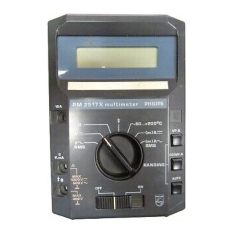
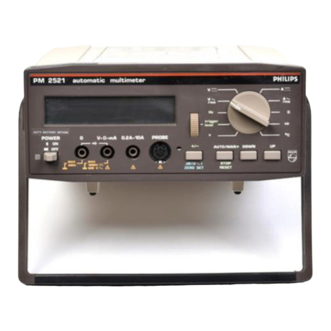
Philips pm2521 User manual

Automatic
Multimeter
PM2521
Operating
Manual/Gebrauchsanleitung/Notice
d’Emploi
<**•
9499
470
17901
830630
/
02
/,.
PHILIPS
Industrial
&
Electro-acoustic
Systems
PHILIPS

Automatic
Multimeter
PM2521
Operating
Manual/Gebrauchsanleitung/Notice
d’Emploi
9499
470
17901
830630
/
02
/.
.
ST
3523
PHILIPS

2
IMPORTANT
In
correspondence
concerning
this
instrument,
please
quote
the
type
number
and
serial
number
as
given
on
the
type
plate.
NOTE:
The
design
of
this
instrument
is
subject
to
continuous
development
and
improvement.
Consequently,
this
instrument
may
incorporate
minor
changes
in
detail
from
the
information
Acontained
in
this
manual.
ft
s
SAFETY
INSTRUCTIONS.
This
equipment
had
been
built
and
tested
according
to
safety
specifications
for
electronic
measuring
equipment
laid
down
by
DIN
57411
part
1/2.80,
VDE
0411
Part
1/2.80,
I
EC
348-11,
and
has
left
the
factory
in
perfect
condition
from
a
safety
point
of
view.
In
order
to
maintain
this
condition
and
to
ensure
the
safe
operation,
the
user
must
follow
the
instructions
and
warning
notices
contained
in
the
directions
for
use.
Prior
to
use
after
storage
and
transport,
the
equipment
should
first
be
examined
for
any
mechanical
faults.
If
there
is
any
doubt
that
the
safety
measures
are
no
longer
adequate,
their
effectiveness
should
be
checked.
If
its
safety
can
no
longer
be
quaranteed,
the
equipment
should
be
taken
out
of
service
and
safeguarded
against
further
use.
Before
opening,
the
equipment
should
be
disconnected
from
all
electrical
sources.
Service
and
repair
work
should
only
be
carried
out
by
experienced
qualified
personnel
and
by
following
the
standard
safety
procedure.
This
equipment
belongs
to
safety
class
110.
Only
the
approved
fuses
must
be
used.
Tlhe
use
of
repaired
fuses
and
the
shorting
of
the
fuse
holder
is
not
permitted.
WICHTIG
Bei
Schriftwechsel
fiber
dieses
Gerat
wird
gebeten,
die
genaue
Typenbezeichnung
und
die
Geratenummer
anzugeben.
Diese
befinden
sich
auf
dem
Leistungsschild.
BEMERKUNG:
Die
Konstruktion
und
Schaitung
dieses
Gerats
wird
standig
weiterentwickelt
und
verbessert.
Deswegen
kann
dieses
Gerat
von
deh
in
dieser
Anleitung
stehenden
Angaben
abweichen.
SICHERHEITSHINWEISE.
Dieses
Gerat
ist
gemass
DIN
57411
Teil
1/2.80,
VDE
0411
Teil
1/2.80,
IEC
348-11,
Schutzmassnahmen
fur
elektronische
Messgerate,
gebaut
und
geprijft
und
hat
das
Werk
insicherheitstechnisch
einwandfreiem
Zustand
verlassen.
Um
diesem
Zustand
zu
erhalten
und
einen
gefahrlosen
Betrieb
sicher
zu
stellen;
muss
der
Anwender
die
Hinweise
und
Warnmerke
beachten,
die
in
dieser
Gebrauchsanleitung
enthalten
sind.
Vor
der
Inbetriebnahme
nach
Lagerung
und
Transport
ist
darauf
zu
achten,
dass
das
Gerat
keine
me-
chanischen
Schaden
aufweist.
Besteht
der
Verdacht,
dass
die
Schutzmassnahmen
nicht
mehr
ausreichend
wirksam
sind,
ist
deren
Wirksamkeit
zu
prufen.
Ist
der
Schutz
nicht
mehr
sichergestellt,
so
ist
das
Gerat
ausser
Betrieb
zu
nehmen
und
gegen
Inbetriebnahme
zu
sichern.
Das
Gerat
ist
vor
dem
Offnen
von
alien
Spannungs-
quellen
zu
trennen.
Wartungs-
und
Uberholungsarbeiten
diirfen
nur
unter
Beachtung
der
gebotenen
Vorsichts-
massnahmen
durch
eingearbeitete
Fachleute
ausgefiihrt
werden.
Dieses
Gerat
ist
ein
Gerat
der
Schutzklasse
11,0.
Es
diirfen
nur
die
vorgeschriebenen
Sicherungen
verwendet
werden.
Die
Verwendung
reparierter
Sicherungen
und
das
Kurzschliessen
des
Sicherungshalters
sind
nicht
zulassig.
IMPORTANT
RECHANGE
DES
PIECES
DETACHEES
(Reparation)
Dans
votre
correspondance
et
dans
vos
reclamations
se
rapportant
a
cet
appareil,
vetyllez
TOUJOURS
indiquer
le
numero
de
type
et
le
numero
de
serie
qui
sont
marques
sur
la
plaquette
de
caracteristiques.'
REM
A
ROUES:
Cet
appareil
est
Tobjet
de
developpemen
ts
et
ameliorations
continuels.
En
consequence,
certains
details
mineurs
peuvent
differer
des
informations
donnees
dans
la
presente
notice
d'emploi
et
d'entretien.
REGLES
DE
SECURITE.
Cet
appareil
a
ete
construit
et
teste
suivant
les
normes
DIN
57411,
premiere
partie
/2.80,
VDE
0411,
premiere
partie
/2.80,
IEC
348-11
mesures
de
protection
pour
appareils
electroniques
de
mesure,
et
il
a
quitte
I'usine
dans
un
etat
impeccable
du
point
de
vue
de
la
technique
de
securite.
Pour
maintenir
cet
etat
et
s'assurer
d'un
functionnement
sans
danger,
I'utilisateur
doit
prender
en
consideration
les
instructions
et
les
avertissements
qui
sont
contenus
dans
le
present
mode
d'emploi.
Avant
sa
mise
en
service
a
la
suite
de
I'entreposage
et
du
transport,
il
convient
de
veiller
a
ce
que
1‘appareil
ne
presente
aucun
endommagement
mecanique.
Si
I'on
soupponne
que
les
mesures
de
protection
ne
sont
plus
suffisamment
efficaces,
il
y
a
lieu
de
verifier
leur
efficacite.
Au
cas
ou
la
protection
n'est
plus
assuree,
I'appareil
doit
etre
mis
hors
service
et
des
dispositions
doivent
etre
prises
pour
garantir
qu'il
ne
sera
pas
utilise.
Avant
d'etre
ouvert,
I'appareil
doit
etre
isole
de
toute
source
de
tension.
Les
travaux
d'entretien
et
de
remise
en
etat
ne
doivent
etre
executes
qu'en
respectant
les
mesures
de
precaution
proposees
par
un
personnel
competent.
Cet
appareil
est
un
appareil
de
la
classe
de
protection
II,
0
.
Seuls,
les
fusibles
presents
peuvent
etre
utilises.
L'utilisation
de
fusibles
repares
et
le
courtcircuitage
du
porte-fusibles
sont
interdits.
©
N.V.
PHILIPS'
GLOEILAMPENFABRIEKEN
-
EINDHOVEN
-
THE
NETHERLANDS
-
1982
PRINTED
IN
THE
NETHEFV^pS

3
CONTENTS
Page
1.
INTRODUCTION
13
2.
TECHNICtfLDATA
14
2.1.
Measuring
performance.
14
2.1.1.
Direct
voltage
measurements.14
2.1.2.
Alternating
voltage
measurements.15
2.1.3.
Direct
current
measurements
.16
2.1.4.
Alternating
current
measurements.
17
2.1.5.
dB
measurements.
18
2.1.6.
Resistance
measurements.19
2.1.7.
Diode
measurements.20
2.1.8.
Temperature
measurements
.20
2.1.9.
Frequency
measurements.21
2.1.10.
Time
measurements
.22
2.1.11.
Trigger
level.23
2.2.
General
data
.
2
4
2.2.1.
Conversion
characteristics
(ADC).24
2.2.2.
Visual
representation
of
the
display.24
2.2.3.
Operation
conditions.^.24
2.2.3.1.
Climatic
conditions.24
2.2.3.2.
Mechanical
conditions.24
2.2.4.
Mains
supply
conditions.25
2.2.4.1.
Mains
supply
voltage.25
2.2.4.2.
Mains
supply
frequency.25
2.2.4.3.
Power
consumption
.
2
5
2.2.5.
Input
terminals
arrangement.25
2.2.6.
Time
function
(ADC)
.25
2.2.7.
Calibration
.25
2.2.8.
Mechanical
.25
2.2.9.
Safety
.25
3.
Accessories
26
3.1.
Accessories
supplied
with
the
PM2521
.’..26
3.2.
Optional
available
accessories.26
3.2.1.
Summary
.26
3.2.2.
Specifications
of
the
optional
accessories
.26
3.2.2.1.
High
Tension
(HT)
probe
PM9246
.
26
3.2.2.2.
Shunt
PM9244
and
Current
transformer
PM9245
.
26
3.2.2.3.
Data
Hold
probe
PM9263
.‘..
.
27
3.2.2.4.
Pt-100
temperature
probe
PM9249
.
27
3.2.2.5.
High
frequency
probe
PM9210
and
accessory
set
PM9212
.28
3.2.2.6.
Dimensions
of
19
inch
rackmounting
set.28

4
Page
4.
PRINCIPLE
OF
OPERATION
29
4.1.
Analog
section.29
4.1.1.
Measuring
voltages,
currents,
resistances
and
diodes.29
4.1.2.
Measuring
time
and
frequency.29
4.1.3.
Measuring
temperatures.29
4.1.4.
**
dB
measurements.29
4.1.5.
Measurements
in
relative
reference
mode.29
1
4.1.6.
Control
of
the
analog
section
.29
4.1.7.
ADC
.29
4.2.
Control
section
.30
4.3.
Display
section.30
5.
INSTALLATION
31
*
5.1.
Mains-supply.31
5.1.1.
Safety
instructions.31
5.1.2.
Replacing
the
mains
fuse
.31
5.1.3.
Adaption
to
the
mains
voltage.31
5.1.4.
Adaption
to
the
mains
frequency
....-•
.31
6.
OPERATION
'
32
6.1.
Switching-on.32
6.2.
Controls.32
6.2.1.
Front
panel.32
6.2.2.
Rear
panel.34
6.3.
Zero
setting.
*
.
3
4
6.4.
Measuring.35
6.4.1.
Standard
measurements.35
6.4.1.1.
Direct
voltage
measurements
(V—
)
.35
6.4.1.2.
Alternating
voltage
measurements
(V~
rms)
.36
6.4.1.3.
Decibel
measurements
(dB)
.37
6.4.1.4.
Direct
current
measurements
(A.-r-O.38
t
6.4.1.5.
Alternating
current
measurements
(A
~
rms)
.39
6.4.1.6.
Resistance
measurements
(£7
).40
6.4.1.7.
Diode
measurements
(
)..41
6.4.1.8.
Temperature
measurements
(°C).42
6.4.1.9.
Frequency
measurements
(Hz)
.43
6.4.1.10.
Time
measurements
(s)
.45
6.4.1.11
.Peak
voltage
measurements.48
6.4.2.
Extended
capabilities
(optional)
.50
6.4.2.1.
High
tension
measurements
.50
6.4.2.2.
High
current
measurements
(Arrr
and
A
~
rms)
.".51
6.4.2.3.
Data
Hold
measurements.52
6.4.2.4.
High
frequency
measurements.53

Page
LIST
OF
FIGURES
Fig.
1.
Accessories
supplied
with
the
PM2521
.
126
Fig.
2.
HT
probe
PM9246
.
126
Fig.
3.
Shunt
PM9244
.
.
.
!.
126
Fig.
4.
Current
transformer
PM9245
.
126
Fig.
5.
Data
Hold
probe
PM9263
.
126
Fig.
6.
Pt-10(ftemperature
probe
PM9249
.
126
Fig.
7.
HF
probe
PM9210
.
130
Fig.
8.
Accessory
set
PM9212.
130
Fig.
9.
Dimensions
for
19
inch
rackmounting
set.
130
Fig.
10.
Basic
built-up
of
PM2521
.
134
Fig.
11.
Block
diagram
of
PM2521
.
134
Fig.
12.
Removing
the
top
cover.
138
Fig.
13.
Adapting
the
mains
transformer
.
138
Fig.
14.
dB
measurements.
37
Fig.
15.
Temperature
pcobe
connection.
42
Fig.
16.
Trigger
level
selection
in
function
Hz.
44
Fig,
17.
Normal
mode
trigger
level
selection
in
function
s
.
45
Fig.
18.
Special
mode
trigger
level
selection
in
function
s.
45
Fig.
19.
Data
hold
connection
.
47
Fig.
20.
Trigger
level
selection
in
peak
voltage
measurerrjent
mode
.
49
Fig.
21.
Peak
voltage
measurements.
49
Fig.
22.
Front
panel.
142
Fig.
23.
Rear
panel.
142
Fig.
24.
Measuring
set-up
for
HT
probe
PM9246
.
146
Fig.
25.
Measuring
set-up
for
shunt
PM9244
.
146
Fig.
26.
Measuring
set-up
for
current
transformer
PM9245
.
150
Fig.
27.
Measuring
set-up
for
data
hold
probe
PM9263
.
150
Fig.
28.
Measuring
set-up
for
high
frequency
probe
PM9210
.
150

6
INHALT
Seite
1.
EINLEITUNG
55
2.
TECHIMISCHEJ5ATEN
56
«
:
2.1.
Messleistung
.56
2.1.1.
Gleichspannungsmessungen
.56
2.1.2.
Wechselspannungsmessungen
.57
2.1.3.
Gleichstrommessungen
.58
2.1.4.
Wechselstrommessungen
.59
2.1.5.
dB
Messungen
.60
2.1.6.
Widerstandsmessungen..61
2.1.7.
Diodenmessungen.62
2.1.8.
Temperaturmessungen.62
2.1.9.
Frequenzmessungen
.63
2.1.10.
Zeitmessungen.64
2.1.11.
Triggerpegel.65
2.2.
Allgemeine
Daten.66
2.2.1.
Analog-Digital
Umsetzung
(ADC)
.
6
6
2.2.2.
Sichtanzeige
.66
2.2.3.
Betriebsbedingungen.66
2.2.3.1.
Klimatische
Bedingungen.!.66
2.2.3.2.
Mechanische
Bedingungen
.66
2.2.4.
Betriebsbedingung
Speisung
nach
IEC359
.
67
2.2.4.1.
Netzspannung
.67
2.2.4.2.
Netzfrequenz.67
2.2.4.3.
Leistungsaufnahme.67
2.2.5.
Anordnung
der
Eingangsklemmen.>.67
2.2.6.
Zeitfunktion
(ADC)
.67
2.2.7.
Kalibrierung
.67
2.2.8.
Mechanische
Daten.67
2.2.9.
Schutz.67
3.
ZUBEHOREN
68
t
3.1.
Zubehoren
im
Lieferumfang
des
PM2521
enthalten.68
3.2.
Wahlweise
erhaltliches
Zubehor.'.68
3.2.1.
Zusammenfassung.68
3.2.2.
Spezifikationes
des
Wahlzubehors.68
3.2.2.1.
Hochspannungs-Messkopf
PM9246.
68
3.2.2.2.
Shunt
PM9244
und
Stromwandler
PM9245
.
68
3.2.2.3.
Messkopf
PM9263
mit
"Data-hold".69
3.2.2.4.
Pt-100
Temperaturmeszfuhler
PM9249
.-.
69
3.2.2.5.
HF-Tastkopf
PM9210
und
Zubehorsatz
PM9212
.70
3.2.2.6.
Abmessungen
fur
19
inch
Gestelleinbau
.70
V

7
Seite
4.
FUNKTIONSPRINZIP
71
4.1.
Analogteil.71
4.1.1.
Messung
von
Spannung,
Strom,
Widerstand
und
Dioden.71
4.1.2.
Messung
von
Zeit
und
Frequenz
.71
4.1.3.
Messung
von
Temperaturen
.71
^1.4.
dB-Messungen
.71
4.1.5.
Messung
in
relativer
Referenz
Betriebsart
.71
4.1.6.
Steuerung
des
Analogteils.71
4.1.7.
Analog-Digital
Umsetzer
(ADC).71
4.2.
Steuerteil
.72
4.3.
Anzeigeteil
.72
5.
INBETRIEBNAHME
73
5.1.
Netzspannung.73
5.1.1.
Sicherheitsvorkehrungen
.73
5.1.2.
Ersetzen
der
Netzsicherung.73
5.1.3.
Anpassung
an
die
Netzspannung.73
5.1.4.
Anpassung
an
die
Netzfrequenz
.'.73
6.
BETRIEB
'
74
6.1.
Einschalten.74
6.2.
Bedienungselemente.74
6.2.1.
Frontplatte.74
6.2.2.
Ruckwand.76
6.3.
Nullsetzen.76
6.4.
Messen.77
6.4.1.
Standardmessungen.77
6.4.1.1.
Gleichspannungsmessungen
(V—.
)
.77
6.4.1.2.
Wechselspannungsmessungen
(V~
rms)
.78
6.4.1.3.
dB-Messungen
(dB).79
6.4.1.4.
Gleichstrommessungen
(A—
).80
*
6.4.1,5.
Wechselstrommessungen
(A~
rms)
.81
6.4.1.6.
Widerstandsmessungen.
8
2
6.4.1.7.
Diodenmessungen
(
-»-
).'.83
6.4.1.8.
Temperaturmessungen
(°C)
.84
6.4.1.9.
Frequenzmessungen
(Hz).85
6.4.1.10.
Z
eitmessungen
(s).87
6.4.1.11.Spitzenspannungsmessungen.90
6.4.2.
Erweiterte
Moglichkeiten
(wahlweise).92
6.4.2.1.
Messung
von
Hochspannungen
.92
6.4.2.2.
Messung
hoher
Strome
(A
—
und
A~
rms).93
6.4.2.3.
Messungen
mit
"Data
hold".94
6.4.2.4.
Hochfrequenzmessungen.95

8
BILDVERZEICHNIS
Seite
Abb.
1.
Mit
dem
PM2521
gelieferte
Zubehoren.
126
Abb.
2.
Hochspannungs
Messkopf
PM9246
.
126
Abb.
3.
Shunt
PM9244
.
126
Abb.
4.
Stromwandler
PM9245
.
126
Abb.
5.
MeszkopfPM9263
mit
"Data
Hold".
126
Abb.
6.
Pt-100
Temperaturfiihler
PM9249
.
126
Abb.
7.
HF
Tastkopf
PM9210.
130
Abb.
8.
Zubehorsatz
PM9212
.
130
Abb.
9.
Abmessung
fur
19
inch
Gestelleinbau.
130
Abb.
10.
Grundaufbau
des
PM2521
.
134
Abb.
11.
Blockschaltbild
des
PM2521
.
134
Abb.
12.
Abnehmen
der
Abdeckel.
138
Abb.
13.
Anpassen
des
Netztransformators
.
138
Abb.
14.
dB-Messungen
.
*.
79
Abb.
15.
Temperaturfuhler.Anschluss.
84
Abb.
16.
Triggerpegelwahl
in
Funktion
Hz.
86
Abb.
17.
Normale
Betriebsart
fur
Triggerpegelwahl
in
Funktion
s.
87
Abb.
18.
Spezielle
Betriebsart
fur
Triggerpegelwahl
in
Funktion
s.
87
Abb.
19.
Data
Hold
Anschluss.,
•.
89
Abb.
20.
Triggerpegelwahl
bei
Messung
von
Spitzenspannungen.
91
Abb.
21.
Messung
von
Spitzenspannungen.
91
Abb.
22.
Frontplatte.-.
142
Abb.
23.
Ruckwand.142
Abb.
24.
Messanordnung
fur
Hochspannungsmesskopf
PM9246
.
146
Abb.
25.
Messanordnung
fur
Shunt
PM9244
.
146
Abb.
26.
Messanordnung
fur
Stromwandler
PM9245
.
150
Abb.
27.
Messanordnung
fur
Messkopf
PM9263
mit
"Data
Hold".
150
Abb.
28.
Messanordnung
fur
Hochfrequenz
Tastkopf
PM9210.
150
t

9
TABLE
DES
MATIERES
Page
1.
INTRODUCTION
97
2.
CARACTERJSTIQUES
TECHNIQUES
98
%
2.1.
Caracteristiques
de
mesure.
98
2.1.1.
Mesures
de
tension
continue.
98
2.1.2.
Mesures
de
tension
alternative.
99
2.1.3.
Mesures
de
courant
continue.100
2.1.4.
Mesures
de
courant
alternat'd.
101
2.1.5.
Mesures
dB
.
102
2.1.6.
Mesures
de
resistance.
103
2.1.7.
Mesure
de
diode.104
2.1.8.
lyiesures
de
temperature.
104
2.1.9.
ft/lesures
de
frequence.105
2.1.10.
Mesures
de
temps.
106
2.1.11.
Niveau
de
declenchement.
107
2.2.
Donnees
generales.
108
2.2.1.
Caracteristiques
de
conversion
(OAD).
108
2.2.2.
Representation
visuelle
de
I'affichage.
108
2.2.3.
Conditions
de
fonctionnement
conforme
a
la
norme
CEI359
.
108
2.2.3.1.
Conditions
climatiques
.
.
.
.
:.
108
2.2.3.2.
Conditions
mecaniques
.
108
2.2.4.
Conditions
d'alimentation
secteur.
109
2.2.4.1.
Tension
secteur
.109
2.2.4.2.
Frequence
secteur.109
2.2.4.3.
Consommation.
109
2.2.5.
Disposition
des
bornes
d'entree.».
109
2.2.6.
Fonction
de
temps
(CAD)
.
109
2.2.7.
Etalonnage
.
109
2.2.8.
Caracteristiques
mecanique.109
2.2.9.
Securite.109
3.
ACCESSOIRES
110
4
3.1.
Accessoires
fournis
avec
le
PM2521
.
110
3.2.
Accessoires
en
option
.•.
110
3.2.1.
Sommaire.
110
3.2.2.
Specifications
des
accessoires
en
option
.
110
3.2.2.1.
Sonde
HT
PM9246
.
110
3.2.2.2.
Shunt
PM9244
et
transformateur
de
courant
PM9245
.
110
3.2.2.3.
Sonde
de
maintien
des
donnees
PM9263
.
Ill
3.2.2.4.
Sonde
de
temperature
Pt-100
PM9249
.
Ill
3.2.2.5.
Sonde
de
haute
frequence
PM9210
et
jeu
d'accessoires
PM9212
.
112
3.2.2.6.
Dimensions
de
montage
en
rack
19
inch.
112

10
Page
4.
PRINCIPE
DE
FONCTIONNEMENT
113
4.1.
Section
analogique.113
4.1.1.
Mesure
de
tensions,
courants,
resistances
et
diodes.
113
4.1.2.
Mesure
de
temps
et
de
frequence.113
4.1.3.
Mesure
de
temperatures.
113
4.1.4.
^
MesuresdB
.
113
4.1.5.
Mesures
en
mode
de
reference
relative
.
113
4.1.6.
Commande
de
section
analogique
.113
4.1.7.
Convertisseur
analogique-digital
(CAD).113
4.2.
Section
commande.
114
4.3.
Section
affichage
.114
5.
INSTALLATION
115
5.1.
Alimentation
secteur.
.
.
.
115
5.1.1.
Instruction
de
securite.
.
.
.
115
5.1.2.
Remplacement
du
fusible
secteur.
...
115
5.1.3.
Adaption
a
la
tension
secteur.
.
.
.
115
5.1.4.
Adaptation
a
la
frequence
secteur
.
.'.
...
115
OPERATION
■
'
116
6.1.
Mise
en
service.
.
.
.
116
6.2.
Commandes.
...
116
6.2.1.
Panneau
avant
.
...
116
6.2.2.
Panneau
arriere
.
...
118
6.3.
Reglage
du
zero.
...
118
6.4.
Mesure.
...
119
6.4.1.
Mesures
standard
.
.
.
.
119
6.4.1.1.
Mesures
de
tension
continue
(V—
).
.
.
.
119
6.4.1.2.
Mesures
de
tension
alternative
(V~
eff)
...
...
120
6.4.1.3.
MesuresdB.
...
121
6.4.1.4.
Mesures
de
courant
continue
(A—
)
.
...
122
*
6.4.1.5.
Mesures
de
courant
alternatif
(A~
eff)
.
.
.
.
...
123
6.4.1.6.
Mesures
de
resistance
(
£2
).
...
124
6.4.1.7.
Mesures
de
diode
(
->f-)
.
\
...
125
6.4.1.8.
Mesures
de
temperature
(°C)
.
...
128
6.4.1.9.
Mesures
de
frequence
(Hz).
...
129
6.4.1.10.Mesures
de
temps
(s).
...
133
6.4.1.11
.Mesures
de
tension
de
Crete
.
...
140
6.4.2.
Possibility
accrues
(en
option).
...
144
6.4.2.1.
Mesures
de
tension
haute
avec
sonde
HT
PM9246
.
.
,
t
.
...
144
6.4.2.2.
Mesures
de
courant
fort
(A
—
et
A~
eff)
.
...
145
6.4.2.3.
Mesures
avec
maintien
des
donnees
.
...
148
6A2.4.
Mesures
de
haute
frequence.
...
149
•
*
V

11
LISTE
DES
FIGURES
Page
Fig.
1.
Accessoires
fournis
avec
le
PM2521
.
126
Fig.
2.
Sonde
HT
PM9246
.
126
Fig.
3.
Shunt
PM9244
.
126
Fig.
4.
Transforfnateur
de
courant
PM9245
.
126
Fig.
5.
Sondfe
de
maintien
des
donnees
PM9263
.
126
•
Fig.
6.
Sonde
Pt-100
PM9249
.
126
Fig.
7.
Sonde
HF
PM9210.
130
Fig.
8.
Jeu
d'accessoires
PM9212.130
Fig.
9.
Dimensions
de
montage
en
rack
19
inch.130
Fig.
10.
Structure
de
base
PM2521
.
134
Fig.
11.
Schema
synoptique
PM2521
.
134
Fig.
12.
Depose
du
couvercle
superieur
.138
Fig.
13.
Adaption
du
transformateur
secteur.138
Fig.
14.
IVlesuresdB
.
<t.
121
Fig.
15.
Connection
de
la
sonde
temperature.
128
Fig.
16.
Selection
du
niveau
de
declenchement
en
fonction
Hz.132
Fig.
17.
Selection
du
niveau
de
declenchement
en
mode
normal,
fonction
s
.
133
Fig.
18.
Selection
du
niveau
de
declenchement
en
mode
special,
fonction
s.
133
Fig.
19.
Connection
de
maintien
des
donnees..137
Fig.
20.
Selection
du
niveau
de
declenchement
en
mode
de
mesure
de
tension
de
Crete.141
Fig.
21.
Mesures
de
tension
de
crSte
.
141
Fig.
22.
Panneau
avant..
142
Fig.
23.
Panneau
arriere
.142
Fig.
24.
Disposition
de
mesure
pour
sonde
HT
PM9246
.
146
Fig.
25.
Disposition
de
mesure
pour
shunt
PM9244
.
146
Fig.
26.
Disposition
de
mesure
pour
transformateur
de
courant
PM9245
.
150
Fig.
27.
Disposition
de
mesure
pour
sonde
de
maintien
des
donnees
PM9263
.
150
Fig.
28.
Disposition
de
mesure
pour
sonde
de
haute
frequence
PM£210.150


13
INTRODUCTION
The
PM
2521
is
a
microcomputer
controlled
digital
multimeter.
The
type
of
microcomputer
used
is
a
8035
with
a
4k
external
ROM.
Thanks
to
the
microcomputer
extra
measuring
functions
are
incorporated,
in
addition
to
the
standard
multimeter
measuring
functions.
These
extra
measuring
functions
make
it
possible
to
measure
the
standard
multimeter
measuring
signals
in
other
units.
)*
The
standard
multimeter
functions
of
the
PM
2521
are:
Alternating
voltage
(V
~
rms)
Direct
current
(A-^r-
)
Direct
voltage
(V
—)
Diodes
(
->p
)
Alternating
current
(A
~
rms)
Resistance
(Q.)
The
extra
measuring
functions
of
the
PM
2521
are:
Temperature
Pt-100
(°C)
Trigger
level
(+/—)
Frequency
{Hz}
Decibels
(dB)
Time
(s)
^
Relative
reference
(zero
set)
A
combination
of
the
trigger
level
function
and
the
time
or
frequency
function,
make
selective
measurements
possible.
The
trigger
level
function
itself
also
enables
peak
voltage
measurements.
The
relative
reference
function
offers
the
possibility
to
select
a
predetermined
relative
reference
point.
Each
subsequent
reading
will
indicate
the
positive
and
negative
deviation
of
the
relative
reference
level.
Each
measuring
function
is
subdivided
into
a
number
of
ranges.
For
range
switching
a
selection
can
be
made
between
manual
or
automatic
range
selection.
To
get
an
optimum
reading
in
the
ac
ranges
an
ac
coupled
rms
convertor
is
built
in
the
PM
2521.
The
periodical
self
calibration
of
the
PM
2521
ensures
high
accuracy
over
a
long
working
period.
The
PM
2521
is
equipped
with
a
5
digit
display.
As
display
a
liquid
crystal
display
is
used.
It
gives
a
very
clear
reading,
especially
under
strong
light
conditions.
Ordering
number
for
the
instruction
sticker
is
9499
470
16401
ST
3523

14
2.
TECHNICAL
DATA
This
apparatus
has
been
designed
and
tested
in
accordance
with
IEC
publication
348,
Safety
Requirements
for
Electronic
Measuring
Apparatus,
and
has
been
supplied
in
a
safe
condition.
The
present
instruction
manual
contains
some
information
and
warnings
which
have
to
be
followed
by
the
user
to
ensure
safe
operation
and
to
retain
the
apparatus
in
a
safe
condition.
All
values
mentioned
in
this
description
are
nominal;
those
given
with
tolerances
are
binding
and
guaranteed
by
the
manufacturer.
Manufacturer
Type
number
Designation
Measuring
quantities
NV
Philips
MIG
S&
I
PM
2521
Digital
multimeter
V
—,
V
~,
A
—,
A~,
U
-N-,
s,
Hz,
°C,
V
peak
2.1.
MEASURING
PERFORMANCE
2.1.1.
Di
rect
voltage
measu
rements
Ranges
Maximum
input
voltage
in
range
2000
V
Resolution
Number
of
representation
units
Accuracy
Temperature
coefficient
Input
impedance
Offset
current
at
input
Series
Mode
Rejection
Ratio
(SMRR)
Maximum
Series
Mode
signal
Common
Mode
Rejection
Ratio
(CMRR)
Maximum
Common
Mode
voltage
Response
time
Zero
setting
Zero
point
drift
mV
200
V
2
-20-200
2000
V
1000
V
10
pV
in
range
200
mV
21000
±
(0,03
%
of
reading
+
0,01
%
of
range)
±
0,01
%
of
reading
/°C
Range
Input
impedance
200
mV
2
V
20
MJ2//60
pF
20
V
11
MJ7//85
pF
200
V
2000
V
10
MJ2//95
pF
<20
pA
86
d.B
for
ac
signals
at
50
Hz
±
1
%
60
dB
for
ac
signals
at
60
Hz
±^j
%
2x
range
end
value
with
exception
of
range
2000
V
(1000
V)
100
dB
for
dc
signals
100
dB
for
ac
signals
of
50
Hz
or
60
Hz
±
1
%
400
V,
560
V
peak
0,7
s
without
ranging
1,5
s
including
ranging
Automatic
zero
setting
of
the
ADC
Manual
with
zero
potentiometer
at
the
front
of
the
PM
2521
5
/iV/°C
between
0
°C
and
35
°C
20
pV/°C
between
35
°C
and
45
°C
With
pushbutton
ZERO
SET
at
the
front
of
the
PM
2521
Relative
reference
setting

15
Maximum
input
voltages
In
all
ranges:
Between
Hi
and
Between
Hi
and
Between
Lo
and
Lo
1000
V
rms
earth
1000
V
rms
earth
400
V
rms
Maximum
VHz
product
10^
2.1.2.
Alternating
voltage
measurements
Ranges
Maximum
input
voltage
in
range
2000
V
Resolution
Number
of
representation
units
Accuracy
(valid
between
3
%
and
100
%
of
range)
Temperature
coefficient
Input
impedance
Common
Mode
Rejection
Ration
(CMRR)
AC
detector
Crest
factor
Response
time
Maximum
input
voltage
mV
200
V
2
20
200
2000
600
V
10
pN
in
range
200
mV
Measured
value
less
than
0,5
%
of
range
is
displayed
as
zero
21000
Range
200
mV
up
to
and
including
200
V
40
Hz-500
Hz
at
20kHz
at
100kHz
±
(0,3%
of
reading
+
0,15%
of
range)
±
(1
%of
reading
+
0,15%
of
range)
±
(5
%of
reading+
1
%of
range)
ST
3354
Range
2000
V
|
40
Hz-
60
Hz
±
(0,3%
of
reading
+
0,15%
of
range)
±
(0,03
%
of
reading
/°C
+
0,01
%
of
range
/°C)
Range
Input
impedance
200
mV
2
V
20
Mfi//60
pF
20
V
11
M£2//85
pF
200
V
2000
V
10
Mfi//95
pF
100
dB
for
dc
signals
80
dB
for
ac
signals
50
Hz
or
60
Hz
±
1
%
RMS
convertor,
ac
coupled
2
at
range
end
1,5
s
without
ranging
3
s
including
ranging
In
all
ranges:
Between
Hi
and
Lo
600
V
rms
Between
Hi
and
earth
1000
V
rms
Between
Lo
and
earth
400
V
rms
Maximum
dc
voltage
400
V
Maximum
VHz
product
10^

Direct
current
measurements
Ranges
2
20
200
mA
2
20
200
A
2
20
Maximum
input
current
in
range
20
A
10
A
Resolution
1
nA
in
range
2
/iA
Number
of
representation
units
2100
Accuracy
Temperature
coefficient
Voltage
drop
over
shunt
Response
time
Protection
±
(0,2
%
of
reading
+
0,05
%
of
range)
±
(0,02
%
of
reading
/°C
+
0,005
%
of
range
/°C)
Range
Voltage
drop
2
/iA
20
/iA
200
/iA
2
mA
<2,5
mV
20
mA
200
mA
<25
mV
2
A
,•20
A
<250
mV
0,7
s
without
ranging
1,5
s
including
ranging
Range
2
/iA
-
20
mA;
250
V
rms
Range
200
mA
-
20
A
are
not
protected
Imax.
=
20
A
for
20
seconds
Maximum
Common
Mode
voltage
Maximum
input
voltages
400
V
rms,
560
V
peak
In
all
ranges:
Between
(Hi
and
Lo
250
V
rms
Between
Hi
and
earth
400
V
rms
Between
Lo
and
earth
400
V
rms

17
2.1.4.
Alternating
current
measurements
Ranges
A
A
2
20
200
mA
2
20
200
A
2
20
Maximum
jnput
current
in
range
20
A
Resoluffon
Number
of
representation
units
Accu
racy
(valid
between
3
%
and
100
%
of
range)
Temperature
coefficient
Voltage
drop
over
shunt
AC
detector
Crest
factor
Response
time
Protection
Maximum
Common
Mode
voltage
Maximum
input
voltage
4
10
A
1
nA
in
range
2
/tA
Measured
value
less
than
0,5
%
of
range
is
displayed
as
zero
2100
40
Hz
-
200
Hz
±
(0,4%
of
reading
+0,15%
of
range)
±
(0,03
%
of
reading
/°C
+
0,01
of
range
/°C)
Range
Voltage
drop
Frequency
2
ju
A
20
ju
A
200
a
A
2
mA
<2,5
mV
50
Hz
20
mA
200
mA
<25
mV
2
A
20
A
<250
mV
RMS
convertor,
ac
coupled
2
at
range
end
1
s
without
ranging
3
s
including
ranging
Range
,
2
a
A
-
20
mA;
250
V
rms
Range
200
mA
-
20
A
are
not
protected
Imax
.
=
20A
for
20
seconds
400
V
rms,
560
V
peak
In
all
ranges:
Between
Hi
and
Lo
250
V
rms
Between
Hi
and
earth
400
V
rms
Between
Lo
and
earth
400
V
rms

dB
measurements
(valid
in
function
V~
rms)
Range
0
dB
reference
Resolution
P
A*-
Number
of
representation
units
Accuracy
Temperature
coefficient
Input
impedance
Common
Mode
Rejection
Ratio
(CMRR)
AC
detector
Crest
factor
Response
time
Relative
reference
setting
Maximum
input
voltages
-57,7
dB
.
.
.
+57,7
dB
1
mW
in
600
£1
,
0
,775
V
or
when
selecting
the
relative
reference
function
with
pushbutton
ZERO
SET
at
the
front
of
the
PM
2521
0,1
dB
Measured
value
less
than
—57,7
dB
is
displayed
as
—99,9
dB
999
Signals
Frequency
Accuracy
-31,7
dB
...
+47
dB
40
Hz-
20kHz
20kHz
-
100kHz
±
0,2
dB
±
1
dB
-50
dB
...
-31,7
dB
40
Hz-
20kHz
+
2
dB
—57,7
dB
...
—50
dB
40
Hz-
20kHz
+
3
dB
>+47
dB
40
Hz-500
Hz
+
1,5
dB
0,02
dB
/°C
Signals
Impedance
.0
V-
1,8
V
20
Mf2//60
pF
1,8V-
18
V
11
ML2//85
pF
18
V
-
600
V
10
ML2//95
pF
100
dB
for
dc
signals
80
dB
ac
signals
50
Hz
or
60
Hz
±
1
%
RMS
convertor,
ac
coupled
2
at
range
end
3s
*
With
pushbutton
ZERO
SET
at
the
front
of
the
PM
2521
In
all
ranges:
Between
Hi
and
Lo
Between
Hi
and
earth
Between
Lo
and
earth
Maximum
dc
voltage
Maximum
VHz
product
600
V
rms
1000
V
rms
400
V
rms
400
V
10
7

19
2
.
1
.
6
.
*
Resistance
measurements
Ranges
Resolutian
Number
of
representation
units
Q
200
2
20
200
2
20
10
m£2
in
range
200
£1
21000
Accu
racy
Temperature
coefficient
Measuring
current
Maximum
voltage
at
the
terminals
with
open
input
Relative
reference
selection
Polarity
of
the
input
terminals
Response
times
Protection
Maximum
input
voltages
Range
Accuracy
200
n
2
kft
'
20
kft
200
kft
±
(0,2
%
or
reading
+0,1
%
of
range)
G
G
CM
O
CM
±
(1
%
or
reading
+0,1
%
or
range)
Range
Temperature
coefficient
200
n
2
kft
20
kfi
200
kft
+
(0,02
of
reading
/°C
+
0,01
%
of
range
/°C
)
2
Mf2
20
Mfi
±
(0,05
%
of
reading
/°C
+
0,01
%
of
range
/
°C
)
Range
Measuring
current
200
n
2
kS2
20
kn
200
2
ML2
20
Mfi
1
mA
1
mA
100
/i
A
lOp
A
1
p
A
100
n
A
4
V
With
pushbutton
ZERO
SET
at
the
front
of
the
PM
2521
—
on
Hi
+
on
Lo
Range
Response
time
200
-
200
kft
0,7
s
without
ranging
2,5
s
including
ranging
G
G
CM
O
CM
2
s
without
ranging
7
s
without
ranging
265
V
rms
In
all
ranges:
Between
Hi
and
Lo
265
V
rms
Between
Hi
and
earth
400
V
rms
Between
Lo
and
earth
400
V
rms
Other manuals for pm2521
2
Table of contents
Languages:
Other Philips Multimeter manuals