Urrea UD77 Dimensions and installation guide

Multímetro Digital
Digital Multimeter
UD77
ATENCIÓN: Lea, entienda y siga las instrucciones de seguridad contenidas en este documento, antes
de operar esta herramienta.
WARNING: Read, understand and follow the safety rules in this document, before operating this tool.
Manual de Usuario y Garantía.
User’s Manual and Warranty.

ESPAÑOL
2
ADVERTENCIA:
FUENTES COMO LAS DE PEQUEÑOS RADIOS PORTÁTILES, TRANSMISORES DE ESTACIONES
DE RADIO, TELEVISIÓN, DE RADIO DE VEHÍCULO Y DE TELÉFONOS CELULARES GENERAN
RADIACIÓN ELECTROMAGNÉTICA QUE PODRÍA INDUCIR VOLTAJES EN LAS PRUEBAS
PRINCIPALES DEL MULTÍMETRO. EN ESOS CASOS LA PRECISIÓN DEL MULTÍMETRO NO ES
GARANTIZADA POR RAZONES FÍSICAS.
CONTENIDO
1. INTRODUCCIÓN 3
2. CONSIDERACIONES DE SEGURIDAD 3
3. EXPLICACIÓN DE LAS FUNCIONES E INDICADORES 4
4. PRUEBAS Y MEDICIONES ELÉCTRICAS BÁSICAS 5
4.1 Medición de voltaje
4.2 Medición de resistencia (resistencia, continuidad)
4.3 Prueba de diodos y diodos de microondas
4.4 Medición de corriente (amperaje)
5. MANTENIMIENTO Y REFACCIONES 10
5.1 Mantenimiento general
5.2 Reemplazo de batería
5.3 Prueba y reemplazo de fusible
6. ACCESORIOS 11
7. ESPECIFICACIONES 11
7.1 Especificaciones
7.2 Rangos máximos
7.3 Especificaciones generales
7.4 Límites de medición

ESPAÑOL
3
1. INTRODUCCIÓN
Este es un medidor portátil operado
por baterías, diseñado y probado de
acuerdo con la publicación IEC 1010-1 (EN
61010-1) (Categoría de sobrecarga III), la
directiva EMC (EN 50081-1 y EN 50082-
1) y otros estándares de seguridad. (vea
especificaciones).
2. CONSIDERACIONES DE
SEGURIDAD
Antes de usar el medidor, lea la siguiente
información cuidadosamente. En este
manual la palabra “ADVERTENCIA” es usada
para condiciones y acciones que ponen en
riesgo al usuario, la palabra “PRECAUCIÓN”
es usada para condiciones y acciones que
pueden dañar el medidor.
Símbolos internacionales.
ADVERTENCIA Voltaje peligroso (Riesgo
de descarga eléctrica)
Corriente Alterna (CA)
Corriente Directa (CD)
CD ó CA
Tierra (Rango de Voltaje aplicado
permitido entre la terminal de entrada
y tierra)
PRECAUCIÓN
Doble aislamiento
(Protección de clase II)
Fusible
ADVERTENCIA: OBSERVE TODAS
LAS MEDICIONES DE PRECAUCIÓN
CUANDO SE MIDAN ALTOS (AS)
VOLTAJES Y/O CORRIENTES. APAGUE
EL CIRCUITO BAJO PRUEBA, PONGA ÉL
MEDIDOR EN LA FUNCIÓN Y RANGO
DESEADO, CONECTE LAS PUNTAS DE
PRUEBA A AL MEDIDOR Y DESPUÉS
AL CIRCUITO BAJO PRUEBA. APLIQUE
ALIMENTACIÓN NUEVAMENTE, SI LA
LECTURA ES ERRÓNEA DESCONECTE
INMEDIATAMENTE Y REVISE
OTRA VEZ TODOS LOS AJUSTES Y
CONEXIONES.
Consejos de Seguridad.
Exceder los límites especificados para este
medidor es peligroso, y puede exponer
al usuario a daños serios y posiblemente
fatales. Para asegurar la seguridad y el uso
apropiado, por favor siga las indicaciones
listadas a continuación.
• No trate de medir ningún voltaje que
exceda de 750V CD o 750V CA RMS.
• Los voltajes arriba de 60V CD o 25V CA
RMS pueden crear serios riesgos de choque
eléctrico.
• No intente usar este medidor si el medidor
o las puntas de prueba han sido dañadas.
• Apagar la alimentación del circuito bajo
prueba antes de trabajar el circuito. Las
pequeñas cantidades de corriente pueden
ser peligrosas.
• Desconecte el cable de prueba energizado
antes de desconectar la punta común.
• Cuando use las puntas de prueba,
mantenga sus dedos lejos de las puntas de
contacto de los cables. Siempre coloque sus
dedos detrás de las guardas de protección
de las puntas de prueba.
Características.
•Mediciones precisas de señales CD no
filtradas (CA rectificadas).
•Pantalla digital de 3 ½ Dígitos, 2000
cuentas.
•Rango manual.

ESPAÑOL
4
•Fusibles con el rango de 10 Amps.
•Voltaje CD básico dentro de los 0,5% de
precisión.
•Retención de datos “Hold”.
•Tono “beep” de continuidad y prueba de
diodo.
•Protección de 600 Volts en medición de
resistencia.
•Indicadores de batería baja y “Hold”
(retención de datos).
•Funda de protección.
•Pantalla LCD grande (68,5mm x 32,7mm).
3. EXPLICACIÓN DE LAS FUNCIONES
E INDICADORES
1. PANTALLA DIGITAL. Las lecturas
digitales aparecen en una pantalla
de 2000 cuentas con indicador de
polaridad. La pantalla se actualiza tres
veces por segundo.
2. Selecciona la alimentación del
medidor encendido o apagado.
3. Congela la lectura digital en la
pantalla.
4. SELECTOR GIRATORIO. Describe las
funciones que son seleccionadas
utilizando el selector giratorio.
Volts CA
Volts CD
Amperes CA
Amperes CD
Resistencia
Prueba de continuidad
Prueba de Diodo
5. La máxima corriente que se puede
medir en esta terminal es de 10 Amps
CD/CA. Esta terminal está protegida por
fusible.
6. Entienda el manual de usuario antes
de usar el medidor.
7. Terminal de entrada de amperaje. La
punta de prueba roja es conectada en
esta terminal para medir corriente en
las funciones de corriente 10A CA o CD.
8. Terminal de entrada de
Miliamperes/Microamperes. La punta
de prueba roja es conectada en esta
terminal para medir mA o µA en las
funciones de corriente CA o CD.
9. El voltaje máximo que este
medidor puede registrar es 1000 V CD
o 750 V CA RMS.
10. Sea extremadamente cuidadoso
cuando se hagan mediciones de alto
voltaje. No toque las terminales o las
puntas de prueba.
11. Terminal de entrada de voltaje,
resistencia, prueba de diodo. La punta
de prueba roja es conectada en esta
terminal para todas las funciones de
V CA, V CD, resistencia, prueba de
continuidad y prueba de diodo.
12. Para evitar una descarga eléctrica
o daño al instrumento, no conecte la
terminal COM a ninguna fuente mayor
a 600 V con respecto a Tierra.
13. Terminal común. La punta de
prueba negra es conectada en esta
terminal para todas las mediciones.

ESPAÑOL
5
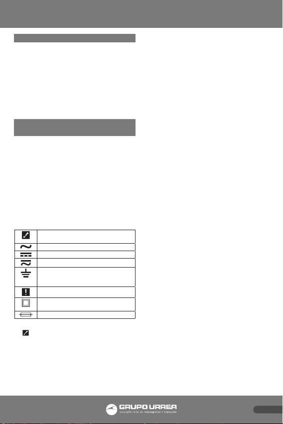
14. Aparece cuando el botón “Hold”
es activado.
15. Polaridad negativa. Indica
automáticamente la polaridad
invertida.
16. Batería baja. Indicador de que
la batería se ha agotado. Cuando
aparece por primera ocasión, restan
al menos 8 horas de vida a la batería.
Reemplace la batería inmediatamente.
Nunca deje una batería descargada o
con poca carga dentro del medidor. Aún
baterías a prueba de fisuras pueden
gotear y dañar el medidor.
17. Indicador de sobrecarga. Mostrado
en la pantalla LCD cuando la entrada es
muy grande para ser mostrada.
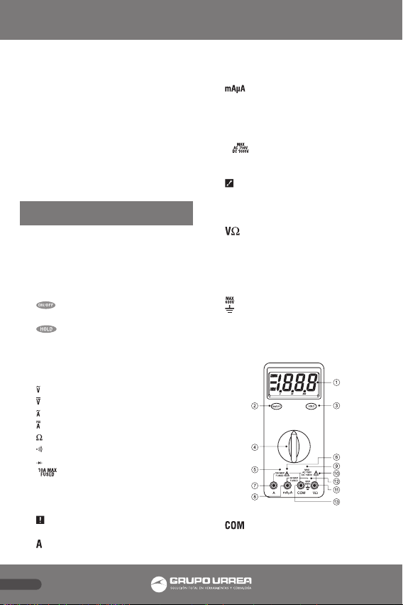
Utilizando las puntas de prueba.
Utilice únicamente el mismo tipo de puntas
de prueba como han sido proporcionadas
con el medidor. Estas puntas están
aprobadas para 1200 Volts, no trate de
medir ningún voltaje mayor a 1000 Volts CD
o 750 Volts CA.
NOTA: En algunos rangos de voltajes CA o
CD con las puntas de prueba no conectadas
en ningún circuito, la pantalla podría
mostrar lecturas fluctuantes debido a la alta
impedancia de entrada. Esto es normal.
Cuando conecte las puntas de prueba al
circuito, la medicón real aparece.
Usando la funda de protección.
El medidor viene con una funda protectora
que absorbe los golpes y protege el medidor
del uso rudo. La funda está equipada con
una base para piso.
4. PRUEBAS Y MEDICIONES
ELÉCTRICAS BÁSICAS
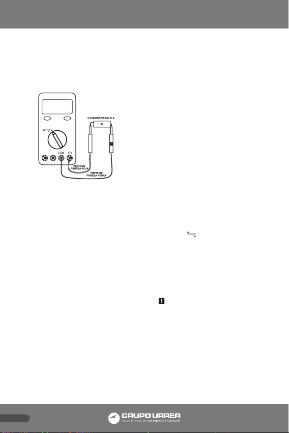
4.1 Medición de voltaje.
ADVERTENCIA: PARA EVITAR EL RIESGO
DE UNA DESCARGA ELÉCTRICA O DAÑO
AL APARATO, LOS VOLTAJES NO DEBEN
EXCEDER 1000V CD O 750V CA (RMS).
NO INTENTE TOMAR MEDICIONES EN
NINGÚN VOLTAJE DESCONOCIDO QUE
PUEDA EXCEDER LOS 1000V CD O 750V
CA (RMS). ESTE MEDIDOR ESTA DISEÑADO
PARA MEDIR CORRIENTE EN CIRCUITOS DE
BAJA ENERGÍA. NO LO USE PARA MEDIR
CIRCUITOS DE ALTA ENERGÍA (LÍNEAS DE
POTENCIA EN FÁBRICAS Y POR LO TANTO
CON GRAN CAPACIDAD DE CORRIENTE).
RESULTA PELIGROSO UTILIZARLO EN
CIRCUITOS DE ALTA CORRIENTE, DEBIDO A
QUE LOS FRECUENTES PICOS DE VOLTAJE
EXCEDEN LA CAPACIDAD DEL APARATO.
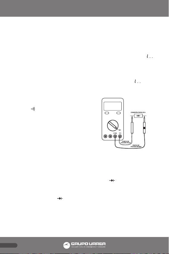
NOTA: Cuando se tomen mediciones de
voltaje, este medidor debe ser conectado en
PARALELO con el circuito o el elemento de
circuito bajo prueba.
•En el rango de 200mV el valor mostrado
puede fluctuar cuando se desconectan las
terminales de entrada. Esto es normal.
•El circuito de medición de voltaje CA
de este medidor es un sistema de valor
medio, por lo tanto una forma de onda
CA diferente a una onda senoidal causa
errores.
•Para mejorar la precisión en las mediciones
de voltajes CD tomadas en presencia de
voltajes CA (como al medir el voltaje CD
“offset” de un amplificador en presencia
de una señal de CA) Mida el voltaje

ESPAÑOL
6
CA primero. Observe el rango del valor
de voltaje CA que se acaba de medir y
seleccione el rango de voltaje CD. Este
método mejora la precisión de voltaje
CD previniendo que la protección de los
circuitos se dispare.
Siga estos pasos para medir voltaje CD (o
de CA):
1. 1. Ponga el selector de función y rango
deseados para V CD o (V CA). Si no sabe
el valor del voltaje a ser medido, siempre
empiece con el rango más alto y reduzca
el rango como lo requiera hasta obtener
una lectura satisfactoria.
2. 2. Conecte la punta de prueba roja en
“VΩ” y la punta de prueba negra en la
terminal COM del instrumento.
3. 3. Desconecte la alimentación del circuito
bajo prueba.
4. Aplique las puntas de prueba al circuito
bajo prueba.
5. Aplique alimentación de nuevo al
circuito, el voltaje medido será mostrado
en la pantalla del instrumento.
6. Si la punta de prueba roja es conectada
en el lado negativo (o de menor voltaje)
del circuito, un signo negativo aparecerá
en la pantalla, en la parte izquierda.
7. Desconecte la alimentación del circuito
antes de desconectar las puntas de
prueba del circuito.
Voltajes trifásicos de AC.
Este medidor está diseñado para medir
voltaje CA doméstico. Cuando se miden
circuitos trifásicos de línea a línea, el valor
del voltaje es de hecho mayor que el voltaje
trifásico medido de línea a Tierra.
Es muy importante que no exceda la
capacidad máxima CA (RMS) de este
medidor, 750 V CA. Para encontrar el
voltaje RMS de línea a línea en una línea
de potencia trifásica, multiplique el voltaje
medido de línea a tierra por la raíz cuadrada
de 3 (aprox. 1,732).
Por ejemplo, si usted conecta este medidor
a una línea trifásica de 480 Volts (i.e. 480 V
de línea a Tierra), el valor total disponible de
voltaje de línea a línea es aproximadamente
832 V CA ( 480 x 1,732). En este caso
puede ocurrir una descarga eléctrica o daño
severo al equipo, debido a que este valor
excede su capacidad.
4.2 Medición de resistencia (resistencia,
continuidad).
PRECAUCIÓN: DESCONECTE LA
ALIMENTACIÓN Y DESCARGUE TODOS LOS
CAPACITORES DEL CIRCUITO QUE SERÁ
PROBADO ANTES DE INTENTAR MEDIR
RESISTENCIAS QUE ESTÉN DENTRO DE UN
CIRCUITO. SI NO SE HACE LO ANTERIOR,
PUEDE GENERAR DAÑOS AL EQUIPO
(Y/O INSTRUMENTOS). EL CIRCUITO
DE MEDICIÓN DE RESISTENCIA APLICA
UN VALOR CONOCIDO DE CORRIENTE
CONSTANTE A TRAVÉS DE LA RESISTENCIA
DESCONOCIDA Y MIDE DESPUÉS EL VOLTAJE
QUE FLUYE POR LA RESISTENCIA. POR LO

ESPAÑOL
7
TANTO, REMUEVA TODA LA ALIMENTACIÓN
DEL CIRCUITO BAJO PRUEBA CUANDO SE
HAGAN MEDICIONES DE RESISTENCIA. SI
CUALQUIER VOLTAJE ESTÁ PRESENTE EN EL
CIRCUITO DE PRUEBA, SE OBSERVARÁ UNA
LECTURA ERRÓNEA. ÉSTE MEDIDOR PUEDE
DAÑARSE SI UN VOLTAJE MAYOR A 600 V
CA ESTÁ PRESENTE.
NOTA: Cuando se miden valores
despreciables de resistencia, junte los cables
de prueba y guarde la lectura. Reste esta
lectura de cualquier medición adicional para
obtener el valor con mayor precisión.
•Cuando se miden resistencias grandes, la
lectura puede ser inestable debido al ruido
eléctrico inducido por el ambiente. En
este caso conecte el resistor directamente
a las terminales de entrada del medidor
o proteja el resistor al potencial de la
terminal de entrada COM para obtener
una lectura estable.
•Para resistencias mayores a 1 M Ω, la
pantalla tomará algunos segundos en
estabilizarse. Esto es normal para estos
casos.
•El medidor cuenta con un circuito para
proteger el rango de resistencia de un
sobrevoltaje (600V CA). Sin embargo, para
prevenir excesos accidentales en el rango
del circuito de protección y para asegurar
una medición correcta, NUNCA CONECTE
LAS PUNTAS DE PRUEBA A UNA FUENTE
DE VOLTAJE cuando el selector giratorio se
encuentre en las funciones Ω o .
•La corriente aplicada durante la medición
de resistencia puede dañar algunos
dispositivos. La siguiente tabla enlista
los voltajes de prueba y la corriente
disponible para cada rango de medición de
resistencia. (Todos los valores son típicos).
NOTA: (A) Es el voltaje de prueba de circuito
abierto en las terminales de entrada, en
Volts. (B) Es la caída de voltaje a través de la
resistencia igual al valor de escala completo.
(C) Es la corriente a través de un corto
circuito en las terminales de entrada.
RANGO VOLTAJE DE
CIRCUITO
ABIERTO (A)
VOLTAJE
DE ESCALA
COMPLETA (B)
CORRIENTE
DE CORTO
CIRCUITO (C)
200 Ω
2 KΩ
20 KΩ
200 KΩ
2 MΩ
20 MΩ
< 1,2 V
< 150 mV
< 550 mV
< 700 mV
< 750 mV
< 800 mV
< 800 mV
< 695 µA
< 470 µA
< 95 µA
< 10,5 µA
< 1,1 µA
< 0,2 µA
4.2.1 Medición de resistencia.
Cuando se mide resistencia, asegúrese de
que el contacto entre los cables de prueba y
el circuito bajo prueba sea bueno. Suciedad,
aceite, pasta de soldadura u otros materiales
extraños pueden afectar seriamente el valor
de la lectura.
1. Ponga el selector de función en la
posición “Ω”.
2. Inserte la punta de prueba negra en la
terminal de entrada “COM” y la punta
de prueba roja en la terminal de entrada
“VΩ”
3. Aplique las puntas de prueba al circuito

ESPAÑOL
8
que será medido.
4. La resistencia medida será mostrada en
la pantalla LCD.
4.2.2 Prueba de continuidad.
Este modo le ayuda a revisar circuitos
eléctricos, tales como cableados, cables de
bocina, conexiones, selectores o relevadores
para circuito cerrado o circuito abierto. En
prueba de continuidad, un valor medido
de aproximadamente 150 Ohms o menos
provoca que el medidor emita un tono
continuo.
Siga estos pasos para checar continuidad:
1. Ponga el selector de función en la
posición “ ”.
2. Inserte la punta de prueba negra en la
terminal de entrada “COM” y la punta
de prueba roja en la terminal de entrada
“VΩ”.
3. Aplique las puntas de prueba al circuito
que será medido.
4. Este medidor emitirá un tono continuo
para resistencias menores a 150 Ohms.
4.3 Prueba de diodos y diodos de
microonda.
La prueba de diodo le permite checar
diodos, transistores y otros semiconductores
en operación normal, en corto o abierto.
NUNCA CONECTE LOS CABLES DE PRUEBA A
UNA FUENTE DE VOLTAJE cuando el selector
giratorio esté en la posición “ ”.
En la prueba de diodo la caída de voltaje en
polarización directa es mostrada cuando el
diodo es polarizado de esta manera. Para un
diodo de Germanio la caída de voltaje típica
es aproximadamente 0,4 volts y en el caso
de un diodo de Silicio, de aproximadamente
0,6 volts.
Evalúe el dispositivo semiconductor como
sigue:
Si la lectura digital en una dirección
muestra un valor y la lectura en dirección
contraria muestra una sobrecarga “ ”, el
dispositivo es bueno.
Si la lectura digital es la misma en ambas
direcciones, el dispositivo probablemente
esté corto.
Si en la pantalla se lee en ambas
direcciones, el dispositivo está
probablemente abierto.
4.3.1 Prueba de diodo.
Siga estos pasos para evaluar un diodo:
1. Ponga el selector de función en la
posición “ ”.
2. Inserte la punta de prueba negra en la
terminal de entrada “COM” y la punta
de prueba roja en la terminal de entrada
“VΩ”.
3. Ponga en contacto la punta de prueba
roja con el ánodo (lado positivo, terminal
sin banda) y la punta de prueba negra
con el cátodo (lado negativo, terminal
con banda).
4. Si el diodo es bueno, la lectura debe

ESPAÑOL
9
indicar entre 0.3 y 0.8 Volts en la pantalla
LCD.
5. Invierta las puntas roja y negra en el
diodo. Si la lectura en la pantalla LCD
indica ( signo de sobrecarga), el diodo
se encuentra en buenas condiciones.
NOTA: Un diodo defectuoso leerá (signo
de sobrecarga) o 0,00 no importa cómo se
conecten las puntas de prueba.
4.3.2 Diodos de microonda.
La mayoría de los diodos de microonda no
pueden ser probados por un DMM con la
función de prueba de diodo. Esto es porque
el DMM no provee suficiente potencia
para encender estos diodos. Se requieren
puntas de prueba que amplifiquen la
potencia de salida, de este modo los
diodos de microonda pueden ser probados
adecuadamente.
4.4 Medición de corriente (amperaje).
PRECAUCIÓN: LAS FUNCIONES DE
CORRIENTE ESTÁN PROTEGIDAS POR UN
FUSIBLE DE 600 V. PARA EVITAR UN DAÑO
AL INSTRUMENTO, NO MIDA FUENTES DE
CORRIENTE QUE POSEAN VOLTAJES DE
CIRCUITO ABIERTO MAYORES A 600 VCD/
VCA.
NOTA: Cuando se realizan mediciones de
corriente, este medidor debe ser conectado
en serie con el circuito (o elemento del
circuito) bajo prueba. NUNCA CONECTE
LAS PUNTAS DE PRUEBA A TRAVÉS DE UNA
FUENTE DE VOLTAJE mientras el selector
giratorio se encuentre en medición de
corriente. Esto puede causar daño al circuito
bajo prueba o a este medidor.
•Para medir corriente, abra el circuito
y conecte las puntas de prueba en dos
puntos de conexión del circuito. La
conexión debe ser en serie con la corriente.
•En medición de corriente alterna, formas
de onda diferentes a la onda senoidal
generan errores.
•Cuando se mide corriente, los resistores
de derivación internos del medidor
desarrollan un voltaje a través de las
terminales del medidor llamado “voltaje
de carga”. Esta caída de voltaje puede
afectar circuitos de precisión o mediciones.
Siga estos pasos para medir corrientes de
CA o CD:
1. Ajuste la función y rango de A CD (o
A CA) deseado. Si no conoce el valor
de la corriente que va a ser medida,
comience siempre con el rango más alto
y redúzcalo conforme lo requiera para
obtener una lectura satisfactoria.
2. Conecte la punta de prueba roja en
la terminal de entrada “mAµA” (si el
rango de 10 A está en uso, conecte la
punta de prueba roja en la terminal de
entrada A) y la punta de prueba negra
en la terminal de entrada “COM” del
instrumento.
3. Desconecte la alimentación del circuito

ESPAÑOL
10
que va a ser probado.
4. Conecte las puntas de prueba en serie
con el circuito que va a ser probado.
5. Vuelva a conectar la alimentación al
circuito, la corriente medida aparecerá
en la pantalla del instrumento.
6. Desconecte la alimentación antes de
remover las puntas de prueba del
circuito.
5. MANTENIMIENTO Y
REFACCIONES
5.1 Mantenimiento general.
ADVERTENCIA: LAS REPARACIONES O
SERVICIOS NO CUBIERTOS EN ESTE MANUAL
DEBEN SER REALIZADOS ÚNICAMENTE
POR PERSONAL CALIFICADO. PARA EVITAR
DESCARGAS ELÉCTRICAS, NO REALICE
REPARACIONES A MENOS QUE USTED ESTE
CALIFICADO PARA HACERLO.
Periódicamente limpie el estuche con
detergente y un paño húmedo; no use
abrasivos o solventes. El agua, la suciedad
o la contaminación en las terminales de
entrada “A” o “mAµA” pueden causar daño
a este medidor.
Este medidor debe ser calibrado anualmente
para mantener sus especificaciones de
mantenimiento.
5.2 Reemplazo de batería.
El medidor usa una batería 9V (NEDA
1604 o IEC 6F22). Para reemplazar la
batería, remueva los dos tornillos del
compartimiento de batería en la parte
trasera del medidor y levante la tapa del
compartimiento. Reemplace la batería.
Inserte la nueva batería, ponga de nuevo
la tapa del compartimiento y reinstale los
tornillos.
5.3 Prueba y reemplazo de fusible(s).
5.3.1 Prueba de fusible(s).
Para probar los fusibles internos de este
medidor:
1. Ponga el selector giratorio en la posición
“ ”.
2. Encienda el medidor.
3. Para probar el fusible F2 (15 A 600
V), conecte la punta de prueba en la
terminal VΩ y póngala en contacto con
la terminal de entrada “A”. La pantalla
debe leer aproximadamente 0,000 V.
Si la pantalla lee (sobrecarga),
reemplace el fusible y pruebe de nuevo.
Si la pantalla lee cualquier otro valor
lleve este medidor a reparación.
4. Para probar el fusible F1 (2 A 600 V)
ahora ponga en contacto la punta de
prueba con la terminal de entrada
“mAµA”. La pantalla debe leer 0.5 V - 0.6
V. Si la pantalla lee (sobrecarga).
Reemplace el fusible. Si la pantalla lee
cualquier otro valor, lleve este medidor
a reparación.
5.3.2 Reemplazo de fusible(s).
1. Desconecte las puntas de prueba.
Remueva la funda de protección del
instrumento.
2. Remueva los tornillos en la parte trasera
del instrumento y separe las cubiertas
trasera y delantera.
3. Reemplace el fusible con uno del mismo
tipo y tamaño del removido.
4. Junte las cubiertas trasera y delantera del
medidor y reinstale los tornillos.

ESPAÑOL
11
5. Reinstale la funda de protección.
6. ACCESORIOS
UD71TLAC - Juego de puntas de prueba y
caimanes.
NOTA: Cuando se le proporcione
mantenimiento al medidor use únicamente
las refacciones especificadas.
7. ESPECIFICACIONES
7.1 Especificaciones.
Laprecisiónestádadacomo±([%delalectura]
+ [ número de dígitos menos significativos]).
Entre 18 °C y 28 °C con humedad relativa de
80% por un período de un año posterior a
la calibración.
Función
Volts CD
Rango Resolución Precisión
200 mV
2 V
20 V
200 V
1000 V
100 µV
1 mV
10 mV
0,1 V
1 V
0,5 %+1 dgt
Impedancia de entrada 10 MΩ
Función
Volts CA
(45Hz a 450 Hz)
Rango Resolución Precisión
200 mV
2 V
20 V
200 V
100 µV
1 mV
10 mV
0,1 V
0,8 %+3 dgts
750 V 1 V 1,2%+3 dgts
Impedancia de entrada 10 MΩ
Función
Ampers CD
Rango Resolución Precisión Caída de
Voltaje
200 µA
2 mA
20 mA
200 mA
2 A
0,1 µA
1 µA
10 µA
100 µA
1 mA
0,8 %+1 dgts
1 mV/µA
100 mV/µA
10 mV/mA
1,2 mV/mA
0,28 V/A
10 A 10 mA 2,0%+10 dgts 0,22 V/A
Función
Ampers CA
(45Hz a 450 Hz)
Rango Resolución Precisión Caída de
Voltaje
200 µA
2 mA
20 mA
200 mA
2 A
0,1 µA
1 µA
10 µA
100 µA
1 mA
1,0 %+3 dgts
1 mV/µA
100 mV/µA
10 mV/mA
1,2 mV/mA
0,28 V/A
10 A 10 mA 3,0%+10 dgts 0,22 V/A
Función
Resistencia
Rango Resolución Precisión
200 Ω 0,1 Ω 0,5 %+10 dgt
2 KΩ
20 KΩ
200 KΩ
2 MΩ
1 Ω
10 Ω
0,1 KΩ
1 KΩ
0,5 %+1 dgts
20 MΩ 10 KΩ 1,0%+2 dgts
Voltaje de circuito
abierto < 1,2 V
Continuidad: EL VOLTAJE DE PRUEBA
DEL CIRCUITO ABIERTO: < 1,2 V UMBRAL
APROXIMADAMENTE: < 150 Ω.
Verificación de diodo: VOLTAJE DE PRUEBA
DEL CIRCUITO ABIERTO: < 3 V MAX
CORRIENTE DE PRUEBA: 1 mA.

ESPAÑOL
12
NOTA:
V CD: RAZÓN DE RECHAZO EN MODO
NORMAL: >46 dB a 50 Hz o 60 Hz.
RAZÓN DE RECHAZO EN MODO COMÚN:
104 dB a CD, 50 Hz o 60 Hz.
V CA: RAZÓN DE RECHAZO EN MODO
COMÚN: >80 dB a CD hasta 620 Hz
PROTECCION DE FUSIBLES: µA or mA : 2 A
600 V fusible RÁPIDO
A : 15 A 600 V fusible RÁPIDO.
Con < 10000 A rango de interrupción.
7.2 Rangos máximos.
Función
Terminales de
Entrada Entrada
Máxima
Punta
roja
Punta
negra
V Ω COM 1000 V
V Ω COM 750 V
V Ω COM 600 V
V Ω COM 600 V
V Ω COM 600 V
A COM 10 A / 600 V
mAμA COM 2 A / 600 V
7.3 Especificaciones generales.
Pantalla digital:
2000 cuentas, 3 actualizaciones por
segundo.
Protección del fusible:
“mA” o “µA”: 2 A, 600 V Alta tensión /
fusible rápido.
“A”: 15 A, 600 V Alta tensión / fusible
rápido.
Temperatura de almacenamiento:
-20 °C a 60 °C (-4 °F a 140 °F).
Temperatura de operación:
0 °C a 45 °C (32 °F a 113 °F).
Altitud:
2 000 m (6,562 pies).
Humedad relativa:
0% a 80% (0 °C a 35 °C, 32 °F a 95 °F).
0% a 70% (0 °C a 35 °C; 45 °F a 95 °F).
Coeficiente de temperatura:
0,1 x (precisión especificada) (-18 °C o - 28
°C; -64 °F o 82 °F).
Tipo de batería:
9 V, NEDA 1604 o IEC 6LR61.
Vida de batería:
350 horas típicamente (alcalina).
Peso:
Sin funda: 380g.
Con funda: 655g.
Dimensiones (A x A x L):
Sin funda: 4 cm x 8,5 cm x 19 cm.
Con funda: 5,4 cm x 10,3 cm x 20,8 cm.
Vibración, impacto:
Diseñado a MIL-T28800 para un
instrumento clase II.
Estuche de protección:
IEC 529 IP30.
Estándares de seguridad:
Diseñado por ambos IEC 1010-1 (categoría
de sobrevoltaje III) y la directiva EMC, UL
1244, CSA C22.2 No 231 e ISA-DS82.
7.4 Límites de medición.
Voltaje CD: 0,1 mV a 1000 V.
Voltaje CA: 0,1 mV a 750 V.
Amperes CD: 0,1 uA a 10 A.
Amperes CA: 0,1 µA a 10 A.
Resistencia: 0,1 Ω a 20 MΩ.
Prueba de continuidad: Umbral aprox. <150
Ω en el rango de 200 Ω.

ENGLISH
13
WARNING:
SOURCES LIKE SMALL HAND HELD RADIO TRASCEIVERS, FIXED STATION RADIO AND
TELEVISION TRANSMITTERS, VEHICULE RADIO TRANSMITTERS AND CELLULAR PHONES
GENERATE ELECTROMAGNETIC RADIATION THAT MAY INDUCE VOLTAGES IN THE TEST
LEADS OF THE MULTIMETER. IN THOSE CASES, ACCURATE READINGS CAN NOT BE
GUARANTEED DUE TO PHYSICAL REASONS.
CONTENIDO
1. INTRODUCTION 14
2. SAFETY CONSIDERATIONS 14
3. EXPLANATION OF CONTROLS AND INDICATORS 14
4. BASIC ELECTRICAL TESTS AND MEASUREMENTS 16
4.1 Voltage measuring
4.2 Resistance measuring (resistance, continuity)
4.3 Diode test & microwave diodes
4.4 Current Measuring (amperage)
5. MAINTENANCE AND REPLACEABLE PARTS 20
5.1 General maintenance
5.2 Battery replacement
5.3 Fuse(s) test and replacement
6. ACCESSORIES 21
7. SPECIFICATIONS 21
7.1 Specifications
7.2 Maximum ranges
7.3 General specifications
7.4 Measurement limits

ENGLISH
14
1. INTRODUCTION
This Meter is a hand-held and battery
operated instrument that is designed and
tested according to IEC Publication 1010-
1 (EN 61010-1) (Overvoltage Category III),
the EMC Directive (EN 50081-1 and EN
50082-1) and other safety standards (see
“Specifications”).
2. SAFETY CONSIDERATIONS
Before using this Meter, read the following
safety information carefully. In this manual,
the word “WARNIING” is used for conditions
and actions that pose hazard(s) to the user;
the word “CAUTION” is used for conditions
and actions that may damage this Meter.
International Symbols.
WARNING Dangerous Voltage (Risk of
electric shock)
Alternating Current (AC)
Direct Current (DC)
Either DC or AC
Ground (Allowable applied voltage range
between the input terminal and Ground)
CAUTION. Refer to the user’s manual
before using this Meter
Double Insulation (Protection Class II)
Fuse
WARNING: OBSERVE ALL SAFETY
PRECAUTIONS WHEN MEASURING HIGHER
VOLTAGES AND/OR CURRENTS. TURN-
OFF POWER TO THE CIRCUIT UNDER
TEST. REAPPLY POWER. IF AN ERRONEOUS
READING IS OBSERVED, DISCONNECT
POWER IMMEDIATELY AND RECHECK ALL
SETTINGS AND CONNECTIONS.
Safety Tips.
• Do not try to measure any voltage greater
than 1000V DC or 750V AC RMS.
• Voltages above 60V DC or 25V AC RMS
may constitute a serious shock hazard.
• Do not attempt to use this Meter if either
the Meter or the test leads have been
damaged.
• Turn-off power to the circuit under test
before cutting, unsoldering or breaking
the circuit. Small amounts of current can be
dangerous.
• Disconnect the live test lead before
disconnecting the common test lead.
• When using the test leads, keep your
fingers away from probe contacts. Always
grip behind the finger guards on the probes.
• Use a current clamp if measuring any
current above 10 Amps.
Features.
•Accurate measurements of non-filtered
(rectified AC) DC signals.
•3 ½ digit, 2000 count digital display.
•Manual ranging.
•Fused 10 Amps range.
•DC voltage basic accuracy within 0.5%.
•Data hold.
•Continuity beeper and diode test.
•600 Volt input protection at resistance
range.
•Hold and Low-battery annunciators.
•Rubber boot (or Safety holster).
•Large LCD display (68.5mm x 32.7mm).
3. EXPLANATION OF CONTROLS
AND INDICATORS
1. DIGITAL DISPLAY. Digital readings are
displayed on a 2000 count display with
polarity indication. The display updates
three times per second.

ENGLISH
15
2. Selects meter’s power ON or
power OFF.
3. Freezes reading in digital display.
4. ROTARY SWITCH. Describes functions
that are selected by setting the rotary
switch:
Volts AC
Volts DC
Amperes AC
Amperes DC
Resistance
Continuity Test
Diode Test
5. The maximum current that you
can measure at this terminal is 10 Amps
DC/AC. This terminal is fused.
6. Refer to the user’s manual before
using this Meter.
7. Amperes Input Terminal. The red test
lead is plugged into this terminal for
measuring current on the 10A AC or DC
current functions.
8. Milliamp / Microamp input
Terminal. The red test is plugged into
this terminal for measuring mA or μA
on either AC or DC current functions.
9. The maximum voltage measuring
capability is 1000V DC or 750 AC RMS.
10. Be extremely careful when making
high-voltage measurements; Do not
touch terminals or test lead probe ends.
11. Volt, resistance or diode test input
terminal. The red test lead is plugged
into this terminal for all AC V, DC V,
resistance, continuity test and diode
test functions.
12. To avoid electrical shock or
instrument damage, do not connect the
COM input terminal to any source of
more than 600V with respect to Ground.
13. Common terminal. The black test
lead is plugged into this terminal for all
measurements.
14. Displayed when the HOLD button
has been pressed.
15. Negative Polarity. Automatically
indicate negative inputs.
16. Low Battery. Battery run-out
warning. When is first displayed,
at least 8 hours of battery life remain.
Replace the battery immediately. Never
leave a weak or dead battery in the
Meter. Even leak-proof types can leak
and damage the Meter.
17. Overload Indication. Displayed
on the LCD when input is too large to
display.
Using Test Leads.
Use only the same type of test leads as
the ones supplied with the Meter. These
leads are rated for 1200 Volts, do not try
to measure any voltage greater than 1000

ENGLISH
16
Volts DC or 750 Volts AC.
NOTE: In some DC and AC voltage ranges
with test leads not connected to any circuits,
the display might show fluctuating readings
due to the high input impedance. This is
normal. When you connect the test leads to
a circuit, a real measurement appears.
Using Holster and Stand.
The Meter comes with a protective holster
that absorbs shocks and protects the
Meter from rough handling. The holster is
equipped with a stand rest.
4. BASIC ELECTRICAL TESTS AND
MEASUREMENTS
4.1 Voltage measuring.
WARNING: TO AVOID THE RISK OF
ELECTRICAL SHOCK AND INSTRUMENT
DAMAGE, INPUT VOLTAGES MUST NOT
EXCEED 1000V DC OR 750V AC (RMS). DO
NOT ATTEMPT TO TAKE AN UNKNOWN
VOLTAGE MEASUREMENT GREATER THAN
1000V DC OR 750V AC (RMS). THIS METER
IS DESIGNED TO WORK WITH WEAK
CURRENT CIRCUITS. DO NOT USE IT FOR
STRONG CURRENT CIRCUITS (POWER LINE
IN FACTORIES AND SO ON HAVING LARGE
CURRENT CAPACITY). USE IN STRONG
CURRENT CIRCUITS IS VERY DANGEROUS
BECAUSE SURGE VOLTAGE IS OFTEN
APPLIED AND IT EXCEEDS THE METER
CAPACITY.
NOTE: When taking voltage measurements,
this Meter must be connected in PARALLEL
with the circuit, or circuit element under
test.
• In 200mV range, displayed value may
fluctuate when disconnecting input
terminals. This is normal.
• AC voltage measuring circuit in this
Meter is of mean value system so an AC
waveform other than a sine wave causes
error.
• To improve the accuracy of DC voltage
measurements taken in the presence of
AC voltages (such as, measuring the DC
offset voltage of an amplifier in the
presence of an AC signal), measure the
AC voltage first. Note the just measured
AC voltage range and select a DC voltage
range. This method improves the DC
voltage accuracy by preventing the input
protection circuits from being activated.
Follow these steps to measure DC (or AC)
Volts:
1. Set function and range switch to the
desired DC V (or AC V) range. If you do
not know the value of the voltage to
measure, always start with the highest
range and reduce the setting as required
to obtain a satisfactory reading.
2. Plug the red test lead into the “VΩ”
input the terminal and the black lead
into the “COM” input terminal of the
instrument.
3. Disconnect the power from the circuit to
be tested.

ENGLISH
17
4. Connect the test leads to the circuit to
be tested.
5. Reapply power to the circuit, the
measured voltage will appear on the
display of the instrument.
6. If the red test lead is connected to the
negative (or lower voltage) side of the
circuit, a minus sign will appear on the
display, at the left side.
7. Disconnect power to the circuit before
removing the test leads from the circuit.
Three-Phase AC Volts:
This Meter is designed to primarily measure
household AC voltage. When measuring
THREE-PHASE circuits line-to-line, the value
of the voltage is actually higher than the
rated line-to-ground 3-phase voltage.
It is very important that you do not exceed
the maximum AC (RMS) rating of this
Meter, which is 750V AC. To find the RMS
voltage line-to-line on a 3-phase power line,
multiply the rated line-to-ground voltage by
the square root of 3 (approx. 1.732).
For example, if you connect this Meter to
a 480 Volts 3-phase line (i.e. 480 V line-to-
ground), the total available line-to-line
voltage is about 832 V AC ( 480 V x 1.732).
Severe damage and a dangerous shock
hazard could result because this exceeds the
rating of this Meter.
4.2 Measuring resistance measuring
(resistance, continuity).
CAUTION: TURN-OFF POWER AND
DISCHARGE ALL CAPACITORS ON CIRCUIT TO
BE TESTED BEFORE ATTEMPTING IN-CIRCUIT
RESISTANCE MEASUREMENTS. FAILURE TO
DO SO MAY END UP IN EQUIPMENT (AND/
OR INTRUMENT) DAMAGE. THE RESISTANCE
MEASURING CIRCUIT APPLIES A KNOWN
VALUE OF CONSTANT CURRENT THROUGH
THE UNKNOWN RESISTANCE AND THEN
MEASURES THE VOLTAGE DEVELOPED
ACROSS IT. THEREFORE, REMOVE ALL
POWER TO THE CIRCUIT UNDER TEST WHEN
MAKING RESISTANCE MEASUREMENT. IF
ANY VOLTAGE IS PRESENT IN THE TEST
CIRCUIT, AN ERRONEOUS READING WILL
RESULT. THIS METER MAY BE DAMAGED
IF VOLTAGE GREATER THAN 600 V AC IS
PRESENT.
NOTE: When measuring critically low
resistance values, touch tips of test
leads together and record the reading.
Subtract this reading from an additional
measurement to obtain the most accurate
value.
•When measuring large resistances, reading
may be unstable due to environmentally
induced electrical noise. In this case,
directly connect the resistor to input
terminals of the Meter or shield the resistor
at potential of the COM input terminal to
obtain stable reading.
For resistance above 1 MΩ, the display
might take a few seconds to stabilize. This
is normal for high-resistance readings.
•The Meter has a circuit to protect the
resistance range from over-voltage (600V
AC). However, to prevent accidentally
exceeding the protection circuit’s rating

ENGLISH
18
and to ensure a correct measurement,
NEVER CONNECT THE TEST LEADS TO A
SOURCE OF VOLTAGE when the rotary
switch is set to Ω or ( ) functions.
•The current applied during resistance
measurements could damage some
devices. The table below lists the test
voltage and current available for each
resistance measurement range. (All values
are typical).
NOTE: (A) is the open circuit test voltage
at the input terminals in Volts. (B) is the
voltage drop across a resistance equal to full
scale value. (C) is the current through a short
circuit at the input terminals.
RANGE OPEN CIRCUIT
VOLTAGE (A) FULL SCALE
VOLTAGE (B) SHORT CIRCUIT
CURRENT (C)
200 Ω
2 KΩ
20 KΩ
200 KΩ
2 MΩ
20 MΩ
< 1,2 V
< 150 mV
< 550 mV
< 700 mV
< 750 mV
< 800 mV
< 800 mV
< 695 µA
< 470 µA
< 95 µA
< 10,5 µA
< 1,1 µA
< 0,2 µA
4.2.1 Measuring resistance.
When measuring resistance, make sure that
the contact between the test leads and the
circuit under test leads is good. Dirt, oil,
solder flux or other foreign matter seriously
affect the read value.
Follow these steps to measure resistance:
1. Set the function switch to the desired
“Ω” position.
2. Insert the black test lead into the “COM”
input terminal and the red test lead into
the “VΩ” input terminal.
3. Connect the test leads to the circuit to
be measured.
4. The measured resistance will be
displayed on the LCD.
4.2.2 Continuity Test.
This mode helps you checking electrical
circuits, such as wiring, speaker cables,
connections, switchers, or relays for short or
open circuits. In continuity test, a measured
value of approx. 150Ω or less causes the
Meter to emit a continuous tone.
Follow these steps to check continuity:
1. Set the Function switch to the “ ”
position.
2. Insert the black test lead into de “COM”
input terminal and the red test lead into
the “VΩ” input terminal.
3. Connect the test leads to the circuit to
be measured.
4. This Meter will emit a continuous tone
for resistances of less than 150 Ohms.
4.3 Diode test & microwave diodes.
Diode test lets you checking diodes,
transistors and other semiconductors for
opens, shorts and normal operation. NEVER
CONNECT THE TEST LEADS TO A SOURCE OF
VOLTAGE when rotary switch is set to “ ”.
In diode test. Drop voltage in the forward
direction is displayed when diode is
connected in this mode. For a Germanium
diode, the typical forward voltage is about
0.4V and in case of a Silicon diode , about
0.6V.
Judge the semiconductor device as follows:
If the digital reading in one direction shows
a value and the reading in reverse direction
shows an overload “ ” the device is
good. If the digital reading is the same

ENGLISH
19
in both directions, the device is probably
shorted. If the display reads “ ” in both
directions, the device is probably opened.
4.3.1 Diode test.
Follow these steps to check a diode:
1. Set the Function switch to the “ ”
position.
2. Insert the black test lead into the “COM”
input terminal and the red test lead into
de “VΩ” input terminal.
3. Touch the red test lead to the Anode
(“+” side, non-banded end) and the
black test lead to the Cathode (“-” side,
banded end).
4. If the diode is in good conditions, the
reading should indicate 0.3V to 0.8V on
the LCD.
5. Reverse the red and black leads on the
diode. If the LCD reads (the overload
sign) the diode is in good conditions.
NOTE: A detective diode will read (the
overload sign) or 0.00 no matter how the
test leads are connected.
4.3.2 Microwave Diodes.
Most microwave diodes can not be tested by
a DMM with a diode test function. This is
because the DMM does not supply enough
power to turn these diode on. A different
kind of test leads that boost the power
output are needed, so that microwave
diodes can be adequately tested.
4.4 Measuring Current (Amperage).
CAUTION: THE CURRENT FUNCTIONS ARE
PROTECTED BY A 600-VOLT RATED FUSE.
TO AVOID DAMAGE TO THE INSTRUMENT,
CURRENT SOURCES HAVING OPEN CIRCUIT
VOLTAGES GREATER THAN 600 VOLTS DC
OR AC, MUST NOT BE MEASURED.
NOTE: When taking current measurements,
this Meter must be connected in SERIES with
the circuit (or circuit element) under test.
NEVER CONNECT THE TEST LEADS ACROSS
A VOLTAGE SOURCE while the rotary switch
is set to Amps. This may damage the circuit
under test or this Meter.
•To measure current, you must break the
circuit and connect the test leads to two
circuit connection points. The connection
must be in series with the current.
•In alternating current measurement,
waveforms other than sine wave cause
errors.
•When measuring current, the Meter’s
internal shunt resistors develop a voltage
across the meter’s terminals called “burden
voltage”. This voltage drop may affect

ENGLISH
20
precision circuits or measurements.
Follow these steps to measure DC (or AC)
Amperage:
1. Set function and range switch to the
desired DC A (or AC A) range. If you do
not know the value of the current to be
measured, always start with the highest
range and reduce the setting as required
to obtain a satisfactory reading.
2. Plug the red test lead into the “mAμA”
input terminal (if the 10A range is
being used, plug the red lead into the
“A” input terminal) and the black lead
into the “COM” input terminal of the
instrument.
3. Disconnect the power from the circuit to
be tested.
4. Connect the test leads in series to the
circuit to be tested.
5. Reapply power to the circuit, the
measured current will appear on the
display of the instrument.
6. Disconnect power to the circuit before
removing the test leads from the circuit.
5. MAINTENANCE AND
REPLACEABLE PARTS
5.1 General Maintenance.
WARNING: REPAIRS OR SERVICING NOT
COVERED IN THIS MANUAL SHOULD ONLY
BE PERFORMED BY QUALIFIED PERSONNEL.
TO AVOID ELECTRICAL SHOCK RISK, DO
NOT SERVICE UNLESS YOU ARE QUALIFIED
TO DO SO.
Periodically wipe the case with a damp
cloth and detergent; do not use abrasives or
solvents. Water, dirt or contamination in the
“A” or “mAμA” input terminals may harm
this Meter.
Calibrate this Meter once a year to maintain
its performance specifications.
5.2 Battery Replacement.
The Meter uses a 9V battery (NEDA 1604
or IEC 6F22). To replace the battery remove
the two screws of the battery compartment
from the back of the Meter and lift off the
cover of the compartment.
Replace the battery. Reattach the battery
compartment to the back of the Meter and
reinstall the screws.
5.3 Fuse(s) Test and Replacement.
5.3.1 Fuse(s) Test.
To test the internal fuses of this Meter:
1. Set the rotary switch to “ ” position.
2. Turn this Meter on.
3. To test F2 fuse (15 A, 600V), plug a test
lead into the VΩ input terminal and
touch the probe to the A input terminal.
The display should read about 0.000V. If
the display reads (overload), replace
the fuse and test again. If the display
reads any other value, have this Meter
serviced.
4. To test F1 fuse (2 A 600V), move the
probe from the “A” input terminal to
the “mAμA” input terminal. The display
should read between 0.5 V and 0.6V. If
the display reads (overload), replace
the fuse and test again. If the display
reads any other value, have this Meter
serviced.
5.3.2 Fuse(s) Replacement.
1. Unplug the test leads. Remove the
rubber boot from the instrument.
2. Remove the screws in the rear of the
Table of contents
Languages:
Other Urrea Multimeter manuals