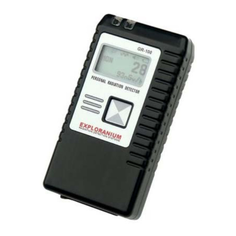
Exploranium KT-9 User manual

1
KT-9 Kappameter
User’s Guide
264 Watline Avenue, Mississauga
(Toronto), Ontario, Canada, L4Z 1P4
Tel (905) 712 3100 • Fax (905) 712 3105
Rev. 1
1
KT-9 Kappameter
User’s Guide
264 Watline Avenue, Mississauga
(Toronto), Ontario, Canada, L4Z 1P4
Tel (905) 712 3100 • Fax (905) 712 3105
Rev. 1

Notice
EXPLORANIUM makes no warranty of any kind with regard to
this material, including, but not limited to, the implied
warranties of merchantability and fitness for a particular
purpose.
EXPLORANIUM shall not be liable for errors or omissions in the
supplied information.
The software supplied as KAPPA1, KAPPA2, CALIB, SCAN7C,
SCAN7 and STICK is provided as is with no implied
warranties.
This document contains proprietary information which is
protected by copyright. All rights are reserved. No part of
this publication may be reproduced, stored in a retrieval
system or transmitted, in any form, or by any means, elec-
tronic, mechanical, photo-copying, recording or otherwise,
without the prior consent of Exploranium G.S. Limited.
© Copyright 1997 Exploranium G.S. Limited
Revision 1
August, 1997
Manual designed, written and produced by GEO F/X

Table of Contents
PREFACE: General information
Introduction, iii
Getting help, iii
Conventions, iv
CHAPTER 1: The KT-9 Kappameter
Features, 1
Design, 4
Controls, 6
Displays, 9
Operating principle and Theory, 10
CHAPTER 2: Using the KT-9
Battery installation, 11
Power ON or OFF,12
Menus, 13
Configuring for right or left-handed use, 15
Selecting mode of operation, 16
Taking measurements, 19
Data handling and memory, 35
If something goes wrong, 38

ii
CHAPTER 3: External sensors, maintenance and
options
External sensors, 39
Maintenance and handling, 42
Batteries and maintenance, 43
CHAPTER 4: Technical reference
Specifications, 47
Parts list and accessories, 48
Display symbols, 49
Error messages, 50
Warranty and repair, 51
CHAPTER 5: Operating the KT-9 from a computer
CALIB —calibration program, 54
KAPPA1—simple data transfer, 57
SCAN7C—PC recording of data from a
manually operated KT-9, 57
SCAN7—remote control & data storage, 59
STICK — scan control from STICK device, 64
APPENDIX A: Technical Notes
KT-5 vs. KT-9 operational differences, 71
PIN vs. NO-PIN modes — comments, 74
INDEX:77

Preface
General information
Introduction
Congratulations on purchasing the KT-9 KAPPAMETER
, the most
advanced, easiest-to-use hand-held susceptibility meter
available today.
This manual provides both instructional and reference material
to help you get the most from your KT-9.
Getting help
If you should encounter a problem with either the KT-9, the
optional external sensors, the applications software or applying
the instrument to a particular problem, please contact
EXPLORANIUM technical support, Monday to Friday from 0900 to
1700 (Eastern Standard Time) at the following numbers:
Telephone: (905) 712-3100
Fax: (905) 712-3105

iv Conventions
Conventions
To help you quickly find information, the KT-9 documentation
follows these conventions:
Symbols Symbol Meaning
Indicates a note of interest, a default or
special condition, or specific critical
information.
Indicates a tip, helpful hint or an
alternate way of doing a task.
Indicates a cautionary note. You should
pay attention to this and proceed
appropriately.
Indicates things you should not do with,
or to, the equipment. Pay special
attention to these items.
You must read this item. It indicates a
critical condition. Please follow the advice
listed.
Indicates a maintenance tip or how to fix
a problem.

Instrument control buttons v
Instrument control buttons
The KT-9 has two control buttons on either side and a
removable push-pin button on the sensor face. The side control
buttons are referred to as the RIGHT or LEFT buttons when you
are looking at the display screen with the sensor facing
upwards.
One of the features of the KT-9 allows you to re-assign the
functions of the buttons depending upon whether you prefer
to hold the instrument in your right or left hand. All the
operations will be described from the point of view of right-
handed use. However, the following special icons will show
when a function is available in the re-mapped modes.
Symbol Meaning
Indicates the physical LEFT button at all
times.
Indicates the physical RIGHT button at
all times.
Indicates the removable PIN on the
sensor face.
Indicates the LEFT button when the
KT-9 is in the right-hand mode (solid
character). Alternatively, this button
can be re-mapped to be the RIGHT
button in the left-hand mode (outline
character).
Indicates the RIGHT button when the
KT-9 is in the right-hand mode (solid
character). Alternatively, this button
can be re-mapped to be the LEFT
button in the left-hand mode (outline
character).

vi Conventions
Instrument display screen
The KT-9 display screen is a five character liquid-crystal display
(LCD). When an action or instructional sequence is being
described, the appropriate display from the instrument will be
shown. A sample screen looks like this:
Type styles
18:888
LoBAT
Style Meaning
Italics 1. A new term is being introduced.
2. An item of importance is being
emphasized.
Bold An action that you are required to
perform.
SMALL CAPS Descriptive or proper name for a mode,
instrument, etc.
Monospaced A filename, environment variable,
directory, menu selection, or any
computer command entered through a
keyboard.
KeyCaps
..
The keys you are required to press
while running an optional computer
program. If these key symbols are not
separated by commas, you must press
all the keys simultaneously.

Chapter 1
The KT-9 Kappameter
The KT-9 KAPPAMETER is the state-of-the-art, hand-held field
magnetic susceptibility meter for obtaining accurate and
precise measurements from outcropping rocks, drill cores and
rock samples. Special design features make the KT-9 superior in
measuring uneven rock surfaces and well suited to automated
drill-core logging with digital recording.
Figure 1 The KT-9 Kappameter
Features
The KT-9 has many unique features over it’s predecessor (the
KT-5 — see also “KT-5 vs. KT-9 operational differences” on
page 71), as well as other commercially available units. These
features include:

2Features
Easy to use – A special measuring pin protrudes from the
centre of the measuring head. In order to take a reading, you
simply press the pin against the sample to be measured. When
you remove the KT-9, it automatically displays the true
measured susceptibility of the sample in SI units.
Hi-sensitivity – The maximum sensitivity of the KT-9 (in com-
mon with the KT-5) is 1x10⁻⁵ SI units. The largest value that can
be read is 999x10-3 SI units. The autoranging capability of the
unit gives it the best sensitivity range available.
True susceptibility – Unlike all other current commercial
instruments, which measure the APPARENT susceptibility, the
KT-9’s automated correcting routines display the TRUE suscepti-
bility. In older instruments, the measured apparent susceptibil-
ity differs significantly from the real susceptibility in the higher
ranges. Users of these instruments would then have to manually
correct the measured data to obtain a true value.
Long battery life – The special power saving techniques used
by the KT-9 allows you to take up to 10,000 readings (under
normal conditions) using a single 9-volt battery.
Uneven samples – The measurement of magnetic susceptibil-
ity is dependent upon the volume of material being sampled.
The presence of an uneven surface (as is the case in most practi-
cal situations) creates air space gaps due to the sensor sitting up
on bumps. This causes serious errors in the measured suscepti-
bility of all other currently available commercial units.
The KT-9 overcomes this problem by spacing the sensor a fixed
distance away from the sample by means of a PIN. The average
of repeated measurements (placing the pin in different loca-
tions) averages the errors due to the bumps to provide the true
reading of the magnetic susceptibility.
There is no reduction in the effective sensitivity of the KT-9 due
to the air gap, because of the automatic compensation built
into the unit.

3
Drill-core samples – Similar to the problem for uneven
samples, the curvature of the drill-core samples creates large
geometric errors to the measured susceptibility in older
instruments. You would have to correct the data manually using
special tables calculated for various drill-core diameters.
The KT-9 automatically corrects the reading since you select the
appropriate core diameter prior to taking measurements.
Fast scanning – The KT-9 has an automatic SCAN mode to
allow larger areas to be scanned quickly for changes in suscepti-
bility. The scan rate is three readings per second—that’s three
times faster than the KT-5!
Variable audio – In the scan mode, the KT-9 has a variable
audio tone that is directly proportional to the measured suscep-
tibility—the higher the tone, the greater the susceptibility. This
allows you to quickly scan a rock surface and visually correlate
areas of varying susceptibility.
Data storage – Up to 10 readings can be stored in the KT-9’s
internal memory. This data is retained even if the unit is pow-
ered off!
Data averaging – The average of up to the 10 stored read-
ings can also be displayed. This allows for very accurate mea-
surement of uneven surfaces while in the PIN mode, as well as
improved data quality for smoother surfaces while in the NO-PIN
mode.
External sensors – The design of the KT-9 permits the con-
nection of various external sensors to the unit via a special con-
nector. When an external sensor is connected, then the internal
sensor is automatically disconnected.
Digital output to a computer – The KT-9 can be connected
to a computer via the serial port and a special cable. The KT-9
can then be completely controlled from the computer in a spe-
cial REMOTE mode. In this mode, the computer can start the KT-9
and store the measured values in a file. This permits core logging

4Design
operations to produce a complete profile of the core in the SCAN
mode.
Soil monitoring – A special stick with the an external sensor
can be connected to the KT-9 to facilitate ground level suscepti-
bility measurement of soils and rocks without you having to
continuously crouch or bend over.
Design
The KT-9 was specially designed to be an easy to use, one-
handed, rugged field instrument.
Rain and dust proof – To this end, the slim instrument case
consists of two isolated compartments. The front compartment
(containing all the electronics, the measuring coil, touch
switches and display) is rainproof and dustproof. The measuring
pin used in the PIN mode, is covered with a rubber shield. When
the pin is removed for the NO-PIN mode, a replacement stud is
installed that maintains the moisture and dust seal to the upper
compartment.
The rear compartment contains the battery and connectors for
the external sensors and computer. The connectors are
protected with special rubber plugs to prevent dirt and water
damage.
Simple one-handed operation – The KT-9 is totally con-
trolled by only two touch switches conveniently located on the
right and left side of the unit. This allows you to use either your
thumb or fore-finger to control the measurements while com-
fortably holding the unit in the palm of your hand. Further, the
KT-9 can be configured to reverse the functionality of the
switches to accommodate both right and left-handed users.
Large LCD display and audio alerts – A simple 5 character
liquid-crystal display with half-inch (12 mm) characters is used.

5
Simple beeps confirm operations when configuring the KT-9 for
the various modes of operation.
In the scan mode, a continuous audio tone that is directly pro-
portional to the measured susceptibility is heard. This facilitates
heads-up operation.
Economical operation – By utilizing the latest technology
CMOS VLSI circuitry, very low power consumption takes place in
the KT-9. Consequently, a single 9-volt battery is usually suffi-
cient for a full season (up to 10,000 readings under normal con-
ditions).
Storage and transportation – A robust leather case is sup-
plied with the KT-9. The case can be either carried over the
shoulder on a strap or worn on a belt to facilitate transporta-
tion in the field. The case has a moulded bottom to accommo-
date the sensor head with the pin in order to prevent the KT-9
from sliding around. Consequently, the unit should be stored
sensor down in the case when not in use.
There is also a small compartment under the lid of the carrying
case for storing a spare battery and some accessories, such as a
spare rubber PIN cover, a PIN assembly or a replacement stud.
Even though the KT-9 has been designed to be a rugged
instrument, it still can be damaged by severe impacts. Also,
please note that the KT-9 is only moisture proof, not water
proof. Consequently, total immersion in water (i.e. falling
into a river, etc.) or long exposure in heavy rains is not advis-
able for either the instrument or the operator.

6Controls
Controls
Figure 2 The controls and features of the KT-9.
1
2
3
5
67
8
4
9
10
6Controls
Controls
Figure 2 The controls and features of the KT-9.
1
2
3
5
67
8
4
9
10

7
TABLE 1: KT-9 controls and features
# Item Description
1LCD Display Up to 5 large characters can
be displayed making it easy
to read under a variety of
conditions
2Right Button Multiple functions:
– main control
– mappable to LEFT function
– ON switch
– referred to by these icons:
3Left Button Multiple functions:
– menu selections
– mappable to RIGHT function
- OFF switch, when pressed at
the same time with the RIGHT
– referred to by these icons:
4Sensor Head This is the active face of the
instrument when using the
internal sensor coil.

8Controls
5Pin This removable measuring
pin is located in the centre
of the top coil assembly. For
ease of use, it behaves as
the RIGHT button for taking
readings. It is referred to by
this icon:
6Computer
connector
The cable to a personal
computer plugs into this
connector.
7Battery compart-
ment screw
This screw secures the cover
to the battery compart-
ment.
8External sensor
connector
External sensors plug into
this connector.
9Battery connector A standard 9-volt battery
connector.
10 Battery extractor
strip
A textile strip to facilitate
battery removal from the
case.
TABLE 1: KT-9 controls and features
# Item Description
The RIGHT and LEFT buttons must be pressed slowly (at least a
one half-second [0.5 sec] push) for proper operation. The
KT-9 is programmed to reject fast button activation as a
means to prevent accidental activation.

9
Displays
The characters that the KT-9 displays are summarized as follows
Character(s) Meaning Description
A: Access: Indicates the mode of mea-
surement can be set
C: Control: Indicates that you can change
from right-handed to left-
handed operation
Cor: Core: The measurement mode is set
for CORE samples
Cdd: Core
Diameter:
Core sample measurement set
for a diameter of “dd” cm
d: Diameter: Core diameter in centimetres
EC: External Coil An external coil is connected
and will be used
ErrX Error: Error number “X” occurred.
See “Error messages” on
page 38.
F: Full: The data memory is full, i.e. ten
readings have been stored
o: Average: The displayed value is the aver-
age of all the data in memory
P: Pin: The measurement mode is set
for the PIN mode
nP: No-Pin: The measurement mode is set
for operation without the pin
in place

10 Operating principle and Theory
Operating principle and Theory
Theory
Magnetic susceptibility is defined as the degree to which a
substance can be magnetized. In mathematical terms, this the
ratio Kof the intensity of the magnetization Ito the magnetic
field Hthat is responsible for the magnetization, i.e.
From Ampere’s law, it is known that a current (i.e. a moving
electrical charge) generates a magnetic field. The inverse
corollary to this is that a magnetic field can also influence a
moving electrical charge. Therefore, put in simple terms, an
oscillating EM field will be influenced to varying degrees by
magnetically susceptible material.
Operating principle
The KT-9 uses a 10 kHz LC oscillator and an inductive coil to
measure the susceptibility. The sequence required to obtain a
measurement of susceptibility is:
1. The frequency of the oscillator is measured in free space.
2. The oscillator frequency is next measured when the coil is
placed on the material for which the susceptibility is
required.
3. The frequency difference is directly proportional to the
materials susceptibility.
4. The susceptibility is calculated from this frequency difference
and takes into account geometric corrections to determine
the true susceptibility.
kH I=

Chapter 2
KT-9
Using the KT-9
Battery installation
The KT-9 is powered by a single 9-volt alkaline battery (type
6F22, IEC standard). The battery compartment is accessed from
the bottom of the instrument by removing the single screw. The
battery compartment is shown in the following figure.
Figure 3 KT-9 battery compartment
Procedure:
1Remove the screw from the bottom cover.
2Remove the bottom cover lid.
3Pull on the fabric tab to free the old battery from the case.
4Detach the old battery from connector

12 Power ON or OFF
5Attach new battery to connector (the design of the con-
nector allows only the correct orientation).
6Insert the new battery into the cavity, ensuring that the
fabric pull tab is behind the battery (for easy removal next
time).
7Replace the cover.
8Insert and tighten the screw.
Power ON or OFF
The RIGHT and LEFT buttons are used to turn the KT-9 ONor OFF.
Power ON
1Press the RIGHT button.
When the KT-9 powers on, the following test display is shown
for about a second:
After this the display will change to last mode that was used.
This convenience allows you to immediately continue opera-
tions where you left off.
If you are going to store your KT-9 for a longer term (over
thirty days), please remove the battery from the unit to pre-
vent damage from electrolyte leakage. It is also recom-
mended that you visually inspect the battery after any long
storage interval.
18:888
LoBAT
Table of contents
Other Exploranium Measuring Instrument manuals
Popular Measuring Instrument manuals by other brands

Huvitz
Huvitz HRK-1 user manual

metrotek
metrotek ETS-1000 Operation manual

Pfeiffer Vacuum
Pfeiffer Vacuum PPT 200 operating instructions

Dwyer Instruments
Dwyer Instruments VP2 Specifications-installation and operating instructions

Veris Industries
Veris Industries E51C2A installation guide

Trotec
Trotec BC 20 operating manual