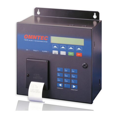
Omntec FuelCheck Installation instructions

F
FU
UE
EL
LC
CH
HE
EC
CK
K
®
®

i
OMNTEC MFG., INC.
FuelCheck
®
Installation &Operating Manual
Document 600300 rev1-1.doc
Revised 11-07-2011
OMNTEC Mfg., Inc.
1993 Pond Road
Ronkonkoma, NY 11779 USA
Phone (631) 981-2001 • Fax (631) 981-2007
www.innovative-sensor.com

2
TABLE OF CONTENTS
System Overview _____________________________________________________________________________________________ 3
Principle of Operation _________________________________________________________________________________________ 4
FuelCheck®Probe ____________________________________________________________________________________________ 5
Probe Construction ________________________________________________________________________________________ 5
Probe Location Considerations_______________________________________________________________________________ 6
Probe Insertion and retraction________________________________________________________________________________ 7
Initial FuelCheck®SAE (standard) probe Installation ____________________________________________________________ 9
FUELCHECK®PROBE REMOVAL WITH (LINE PRESSURE < 300 PSI)__________________________________________ 13
FUELCHECK®PROBE REINSERTION with (PRESSURE <300 PSI)______________________________________________ 15
Fiberoptic Interconnect Cable __________________________________________________________________________________ 17
FuelCheck®Controller________________________________________________________________________________________ 21
System Calibration___________________________________________________________________________________________ 25
Fluid Temperature Correction __________________________________________________________________________________ 28
FuelCheck®System Specifications ______________________________________________________________________________ 30
FuelCheck®Probe________________________________________________________________________________________ 30
FuelCheck®Controller ____________________________________________________________________________________ 30
Optional Equipment Installed in Controllers with Serial Numbers______________________________________________________ 31
APPENDIX A Warranty and Disclaimer__________________________________________________________________________ 35
APPENDIX B Acromag Series 611T/612T SIGNAL CONDITIONER _________________________________________________ 37
APPENDIX C OMEGA CN132 TEMPERATURE CONTROLLER ___________________________________________________ 38
APPENDIX D Acromag BusWorks® Model 952N-4012 Modbus TCP/IP Industrial I/O Module __________________________ 39
APPENDIX E Fiberoptic Connectorizing Kit ______________________________________________________________________ 40
APPENDIX F UV Resistant Cable Additional Documentation ________________________________________________________ 41

3
System Overview
FuelCheck®is a totally fiberoptic process refractometry system designed to
provide accurate interface discrimination in product pipelines.
FuelCheck®Is comprised of 3 basic components; namely:
1. FuelCheck®Probe
Part No. FU-PR-24
2. Fiberoptic interconnect cable
Part No. FU-C2-CC (conduit cable) FU-C2-DB (direct burial) FU-C2-UV (UV resistant)
3. FuelCheck®Controller
Part No. FU-CT-*I (* represents number of channels up to 3, ie. FU-CT-1I)
FuelCheck®is designed for easy installation, convenient calibration, and very low maintenance.
The following chapters will describe the principle of operation, installation considerations, and
system calibration and operation.
Figure 1
FuelCheck System Architecture
Chapter
1

4
Principle of Operation
FuelCheck®is a totally fiberoptic system for measuring the index of refraction of fluids in petro-
leum pipelines.
The FuelCheck®Controller incorporates an extremely stable fiberoptic light source and detector.
This stability is provided by maintaining the source and detector circuitry at a constant tempera-
ture. Light from the infrared LED light source is coupled into the source fiber of the fiberoptic in-
terconnect cable. The FuelCheck®Probe reflects light from the source fiber to the detector fiber.
Some of the light is refracted into the fluid in which the probe lens is immersed. The amount of
light that is refracted (lost) from the lens is directly proportional to the index of refraction of the
fluid in which the probe lens is immersed. Thus, the higher the fluid’s index of refraction, the less
amount of light is returned to the detector in the FuelCheck®Controller.
5 mm
1. Sensor is a 5 mm diameter
sapphire hemisphere.
2. Optical fibers are very precisely
fused onto the flat side of the lens.
3. An LED is used to provide
constant intensity light to the lens
through either of the fibers. (LED
located in the FuelCheck
Controller, up to 2 km away from
sensor)
4. The inner surface of the lens acts
as a mirror: some of the light
reflects inside the lens; however,
some light refracts out of the lens
into whatever fluid is wetting the
lens. The amount of light lost to
refraction is directly proportional
to the refractive index of the fluid
wetting the lens.
5. Whatever light is not lost to
refraction returns to the
FuelCheck Controller via the other
fiber where its intensity is
precisely measured and converted
to a scaled value.
reflected
light
refracted
light
fiberoptic length
up to 2 km
FuelCheck
FuelCheck Operating Principle
Figure 2
Principle of Operation

5
FuelCheck®Probe
Part No. FU-PR-24
The FuelCheck®Probe is readily installed into the pipeline through a full opening valve. Its in-
stallation should ensure constant contact with fluids to ensure instantaneous and positive inter-
face detection.
Probe Construction
The FuelCheck®Probe, part number FU-PR-24, is constructed of heavy-wall ½” OD stainless
steel tubing. Standard probe length is 24” giving an insertion length of 16” from the top of the
valve to the ID of the pipeline. With probe and insertion tool changes, the Probe can be made in
virtually any length so as to
accommodate almost any
installation requirement.
The maximum operating
pressure and temperature
are 1,500 PSI @ 200°F.
The materials of construc-
tion allow for use in all petro-
leum fuels with all known
additives, including MTBE.
The sapphire lens is ex-
tremely resistant to both
chemicals and abrasion.
The sensor element incor-
porates an o-ring seal with a
Teflon backup seal. The
sensor element cannot be
replaced therefore replacing
the probe will be required if
the probe is moved or
crimped at the wrong loca-
tion on the probe body. The probe incorporates a safety stop which is an 11/16” OD upset
welded onto the probe body to prevent the probe from passing through the process insertion fit-
ting.
Chapter
2
FuelCheck®Probe
process insertion fitting
insertion tool adapter
pipeline access valve
(>= 1” full-opening)
threadolet (>=2”)
flexible armor
probe body
conduit J-box
Figure 3
FuelCheck Probe installed in pipeline

6
The process insertion fitting is a specially modified bored-through Swagelok tubing adapter. An
internal o-ring groove incorporating a back-up ring has been machined into the fitting to provide a
pressure seal with the probe body during process insertion and retraction. The process insertion
fitting is an integral part of the FuelCheck®probe and cannot be removed in the field.
The Insertion Tool adapter en-
ables the use of the high pressure
probe Insertion Tool in the event
that the probe must be inserted or
removed from the process at
pressures exceeding 300 PSI.
Even if the process pressure is
never expected to exceed 300
PSI, it is recommended that this
adapter be used as a safety fea-
ture so that the probe could be
removed in the event of an emer-
gency.
The top end of the probe is at-
tached to a length of 3/8” OD
stainless steel flexible conduit
(“armor”) providing protection for
the fiberoptic probe lead. Stan-
dard length is 120”. This armor is
terminated in a ½” MNPT conduit
fitting which is attached to the
probe junction box. The fiberoptic
leads are terminated with ST type
fiberoptic connectors which attach
to the fiberoptic interconnect cable
leading to the FuelCheck®Con-
troller.
A fiberglass junction box (J-Box) is
provided to protect the fiberoptic
connection between the probe and the fiberoptic interconnect cable. This J-box is normally the
terminus of a rigid or EMT conduit installed to protect the fiberoptic interconnect cable.
Probe Location Considerations
FuelCheck®probes can be installed through any full-opening valve with an inside diameter (ID)
of 1” or larger; however, several considerations should be observed in order to provide optimum
performance. It is strongly recommended that the probe be installed such that its tip not protrude
past the inside wall of the pipeline. If the probe extends into the pipeline, damage to the pipeline
and probe can result by pigging the line without removal of the probe. If the probe location is not
to be pigged, the probe can be installed into the pipeline to the desired length but fluid velocity
Figure 4
Process Insertion O-Rings

7
and fluid density should be considered to insure any type of harmful harmonics are produced
(Call ISS Ltd for harmonic calculation if required).
When the probe is to be installed flush with the ID of the pipeline so as to accommodate pigging,
several factors must be considered. First, it is recommended that the fixture (i.e., weldolet) in
which the tip of the probe (i.e., the sensor element) will reside be of sufficient diameter and suit-
able location such that fluid turbulence will provide adequate sampling. If this fixture is too small,
fluid stagnation could occur resulting in a failure of the system to detect the interface. It is there-
fore recommended that the probe inser-
tion weldolet be at least 1” in diameter
so that adequate mixing takes place
thus allowing for very rapid interface
detection. It is also important that the
weldolet bit size be as large as possi-
ble. Too often, it has been observed
that a large weldolet was installed but
that the hole bored through the pipeline
was very small.
The location and orientation of the
probe insertion weldolet is also impor-
tant. Placing the probe near an elbow
in the line will provide greater turbu-
lence and more rapid interface detec-
tion. Insertion of the probe in the top of
the pipeline should be avoided since a
vapor pocket could develop in the wel-
dolet. Insertion from 45° from vertical to the side is preferable, though care must be taken to
provide sufficient clearance for convenient installation and removal.
Some general recommendations for probe location and orientation are as follows:
1. Try to mount the FuelCheck probe in a location where the pipe is always full, even when
the line is not flowing.
2. NEVER mount the FuelCheck probe on a densitometer loop.
3. Never mount the probe on the top of the pipe since vapor can get trapped there.
4. Never mount the probe on the bottom of the pipeline because the threadolet can become
filled with dirt, rust, or other particles from the pipeline.
Probe Insertion and retraction
The FuelCheck®Probe has been designed to be safely inserted into and retracted from the
process. These instructions must be followed to prevent injury and damage to the equipment.
Figure 5
Suggested Probe Installation Method

8
Appropriate safety equipment should always be used (i.e., safety glasses, and fire-retardant
clothing).
The probe should always be installed in close proximity to a reliable pressure gauge or the pres-
sure must be known when performing these operations. When installing a FuelCheck®Probe
for the first time, the following procedures must be followed. It is imperative that all client safety
procedures be followed explicitly, and that engineering specifications (i.e., threaded connection
compounds, sealants, tightening torque, etc.) be strictly adhered to. Probe installation, removal,
insertion, retraction, etc. should only be undertaken by qualified and authorized personnel.
These procedures require 2 people to perform the operation.
Note - Probe Insertion and Retraction instructions included in this manual are for low (<300 PSI)
and high pressure (>300 PSI) applications. Select correct procedure for operation desired. Each
procedure has its on tools and operating instructions and will require special training before per-
forming operation.
Figure 6
Low Pressure Insertion

9
Initial FuelCheck®SAE (standard) probe Installation
Low Pressure Installation
IMPORTANT: Note line pressure. If over 300 PSI (2000 kPa) follow instructions for high-
pressure installation.
NOTE - Make Initial measurement “A” before starting to install probe into pipeline.
1. Use Teflon tape or required sealing compo-
nents on the Insertion Tool Adapter and in-
stall Adapter on the Valve. Measure precise
length from pipeline to the to top of Insertion
Tool Adapter (Figure 3). Record this length
as measurement “A”.
2. Use ½ of the wall thickness on the pipeline to
ensure the tip of the probe is not intruding
into the pipeline. Calculate and record Probe
o-ring groove
machined into fitting
sensor element
safety stop
access valve
Insertion Tool Adapter
ENLARGED
CUTAWAY
Process Insertion Fitting
SAE/MS STRAIGHT THREAD
Insertion Tool
Adapter
Valve
A
Figure 7
Probe Alignment
Figure 8
Insertion Valve measurement

10
Insertion Length (L) as follows:
L = A + ½ wall thickness
3. Clean and lubricate exposed probe body using light machine oil or a grease to avoid damag-
ing o-ring seals.
4. Tighten the Hex cap on the Process Insertion Fitting. Move the Process Insertion Fitting up
the probe body until the exact distance calculated in Step 2 is reached. This distance L, will
be from the bottom of the probe body to the bottom of the Hex nut on the Process Insertion
Fitting. Make a mark on probe body at the top of the hex cap (Figure 4) using an indelible
marker.
5. Apply a lubricant to the probe body. Slide the
Process Insertion Fitting down the Probe Body
until it touches the safety stop and install in the
Insertion Tool Adapter.
6. Secure the Insertion Tool Adapter from turning
while tightening the Process Insertion Fitting,
(Figure 5).
Figure 6
Need new picture
L
Mark probe body
here
Figure 9
Marking Insertion Length on Probe
Figure 10
Tightening the process insertion fitting

11
7. Verify Process Insertion Fitting is snug against safety stop by
pulling upward on the probe body.
8. Open valve slowly and check for leaks.
9. Using low-pressure probe insertion handle, push probe
into pipeline (figure 6) until indelible mark is aligned
with top of the Process Insertion Fitting. Tighten Hex
nut on the fitting exactly 1¼ turns.
Figure 9
Pull
Upward
Figure 11
Safety stop
Figure 12
Check for leaks
Figure 13
Push probe into
pipeline

12
10. Again, check entire fixture for leaks and attach Warning Placard (Figure 9) to valve handle
and probe body using cable tie.
WARNING
WARNING
•DO NOT CLOSE VALVE
•DO NOT LOOSEN FITTINGS
FuelCheck™ Probe installed through valve
please refer to FuelCheck™ Operating Manual
before attempting to remove FuelCheck™ Probe
Figure 14
Warning Placard

13
FUELCHECK®PROBE REMOVAL WITH (LINE PRESSURE < 300 PSI)
Positively ascertain line pressure is less than 300 PSI or 2000 KPA.
NOTE: At 300 PSI, the upward force on the probe will be about 60 lb. Attach low pressure inser-
tion handle to probe. Hold inward force on handle without standing in line with the probe axis.
1. Another person must loosen the Process Insertion Fitting
nut while holding a backup wrench on the process inser-
tion fitting.
2. When the Process Insertion Fitting Nut is free, the person
holding the probe handle should allow the process pres-
sure to gradually allow the probe to be retracted until the
safety stop comes to rest against the insertion fitting
(probe fully retracted).
3. Close the valve slowly and completely.
Figure 17
Loosen fitting
Figure 15
Ease probe out
Figure 16
Close valve

14
4. Place a backup wrench on the Insertion Tool Adapter.
Remove the Process Insertion Fitting from the Insertion
Tool Adapter taking care not to spill any process fluid. The
use of hydrocarbon absorbing padding is suggested to
prevent environmental contamination. Be sure to dispose
of contaminated padding properly.
Figure 18
Remove probe

15
FUELCHECK®PROBE REINSERTION with (PRESSURE <300 PSI)
Positively ascertain line pressure is less than 300 PSI or 2000 KPA.
1. Make sure probe is fully retracted (safety stop
against bottom of insertion fitting). Install probe
onto Process Insertion Fitting and tighten insertion
fitting to valve. Make sure Swagelok nut is hand-
tight.
2. Open valve slowly and fully. Again, carefully check for
leaks and repair as needed.
3. Clean and lubricate exposed probe body with light ma-
chine oil or a grease to avoid damaging o-ring seals.
4. When certain of a no-leak status, attach low-
pressure probe insertion handle to probe. Push
probe into pipeline.
Figure 19
Attach probe
Figure 20
Open valve
Lubricate probe
Figure 21
Insert probe into
pipeline

16
5. Tighten Hex nut until snug.
6. Again, check entire fixture for leaks.
7. Reattach Warning Placard to valve han-
dle and probe body using cable tie.
Figure 18
Figure 22
Tighten Swagelok
Check for leaks
WARNING
WARNING
•DO NOT CLOSE VALVE
•DO NOT LOOSEN FITTINGS
FuelCheck™ Probe installed through valve
please refer to FuelCheck™ Operating Manual
before attempting to remove FuelCheck™ Probe
Figure 23
Reattach warning placard

17
Fiberoptic Interconnect Cable
Part No. FU-C2-CC (conduit cable) FU-C2-DB (direct burial) FU-C2-UV (UV resistant)
Thefiberoptic interconnect cableis used toprovide a stableopticalconnectionbetween the
Probeand the FuelCheck®Controller
If the fiberoptic interconnect cable is to be installed into a rigid or EMT conduit, the inexpensive
zipcord fiberoptic cable may be employed. The specifications for this cable are shown on the fol-
lowing page.
When installing the fiber, several rules must be followed to avoid damaging it.
1. Do not pull the fiber around sharp obstructions which may cut the fiber…
2. Never step on the fiber.
3. Do not kink the fiber when installing it: make certain to unspool the fiber rather than allowing
it to spin off the end of the spool, which can result in twists and kinks in the fiber.
4. Do not exceed the maximum pulling stress of the fiberoptic cable. On long runs, it is recom-
mended that a suitable lubricant be employed.
5. Do not exceed the minimum bend radius (~ 1”).
6. Do not install when the temperature is below -20°F.
7. IMPORTANT: In areas where winter temperatures are extremely cold, precautions
must be taken to prevent water from entering conduit runs as the force exerted by ice
formation can seriously damage the fiberoptic cable. If such precautions aren’t feasi-
ble or practical, use of the PE jacked fiberoptic cable should be strongly considered.
8. On short fiber runs to be undertaken inside conduit deemed to be in good condition and not
containing any other cables, the fiberoptic cable can be supplied pre-connectorized. It is rec-
ommended that the conduit run be carefully measured and that sufficient excess be allowed
for easy connection to the FuelCheck®Controller.
Chapter
3

18
9. If the fiberoptic connectors are to be installed after the fiber is pulled into the conduit, it is im-
perative that sufficient excess (<10 ft) be left on each end so that the connectors can be at-
tached conveniently.
10. The procedures for installation of the fiberoptic connectors on the fiberoptic cable is specific to
the cable type and the connector type, and must be performed by a trained technician.
These instructions assume the fiberoptic cable has already been performed.
11. Due to possible wide temperature changes, a stabilizer is required over the connectors and
mating sleeve located in the probe conduit j-box. The following steps will perform this re-
quirement..
a) Spread open the slit and place the stopper over the fiberoptic interconnect cable and the
FuelCheck®probe cable as shown. Attach the ST mating sleeve to the ST connector on
the interconnect cable.
b) Attach stabilizer tube to stopper as shown leaving the connector protruding from the end.
c) Apply a small dab of optical gel to the tips of the Probe ST connector by dipping it into the
optical gel container. Be careful not to allow any dirt to get into the gel.
Figure 24
Insert fiber in stopper
Figure 25
Attach Stabilizer Tube
Figure 26
Apply optical gel
FU-FO-CN
(fiberoptic connector) FU-FO-MS
(fiberoptic mating sleeve)

19
d) Connect the probe’s ST connector to the mating sleeve.
e) Draw the stabilizer tube assemble together by carefully pulling the interconnect cable fiber
through the holes in the stopper. Make sure the stoppers are snug in the stabilizer tube
and the fibers are straight.
f) Complete steps a thru e on the second set of ST connectors.
g) Using the cable ties secure the longer tube to the shorter tubes. The longer tube is used
as a support to eliminate excessive force being applied to the fiber. Place the three tubes
in the junction box and coil fiber to fit, while watching bend radius.
Figure 27
Attach mating sleeve to FO connectors
Figure 28
Make up stabilizer tubes
Figure 29
Secure stabilizer tubes with cable ties
Table of contents
Other Omntec Measuring Instrument manuals