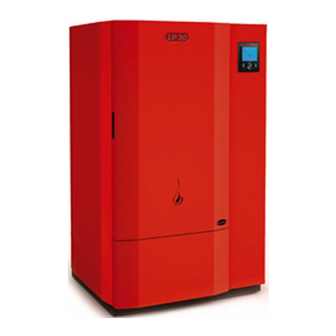
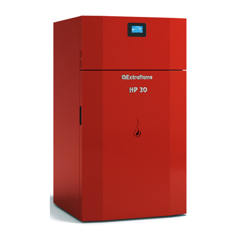
Extraflame TERMOPELLET TC30 User guide

TERMOPELLET TC30
Read the instructions carefully before installation, use and maintenance.
The installation must be carried out by qualied sta.
The instruction book is an integral part of the product.
Installer manual
PELLET AND WOOD BOILERS

2

3
Index
Chapter 1
SUPPLY CONDITIONS ............................................................................................................................... 5
Chapter 2
TRANSPORT AND STORAGE .................................................................................................................... 7
Chapter 3
MOUNTING PHASES ................................................................................................................................. 8
POSITIONING THE BOILER BODY.......................................................................................................................................8
MOUNTING THE REAR COVERING.....................................................................................................................................9
INSTALLATION................................................................................................................................................................. 11
CONNECTION TO THE SMOKE EVACUATION SYSTEM..................................................................................... 12
CHIMNEY OR INDIVIDUAL FLUE............................................................................................................................... 13
APPLIANCE CONNECTION TO THE FLUE AND FUEL PRODUCTS EVACUATION.................................... 15
CHIMNEY CAP ................................................................................................................................................................. 15
CONNECTION TO EXTERNAL AIR INLETS ............................................................................................................. 16
INSULATION, FINISHINGS, COVERING AND SAFETY RECOMMENDATIONS .......................................... 16
NATIONAL, REGIONAL, PROVINCIAL AND TOWN COUNCIL REGULATIONS.......................................... 16
Chapter 4
HYDRAULIC PLANT CONNECTION ........................................................................................................17
OPEN VESSEL PLANT........................................................................................................................................................... 17
GENERALITY..................................................................................................................................................................... 17
OPEN EXPANSION VESSEL.......................................................................................................................................... 17
SAFETY PIPE AND LOAD PIPE ................................................................................................................................... 18
CLOSED VESSEL PLANT FOR MANUAL AND AUTOMATICMANUAL FEEDING APPLIANCES................. 18
SAFETY VALVE................................................................................................................................................................. 19
CLOSED EXPANSION VESSEL..................................................................................................................................... 19
GENERALITY.............................................................................................................................................................. 19
CLOSED EXPANSION VESSEL CONNECTION ................................................................................................ 20
MOUNTING OF HEAT DISCHARGE VALVE NOT SUPPLIED................................................................................. 20
AUTOMATIC THERMOSTATIC VALVE.............................................................................................................................. 21
INSTALLATION AND SAFETY DEVICES ......................................................................................................................... 21
STORAGE TANK DIMENSIONING..................................................................................................................................... 22
COMMISSIONING CHECKS................................................................................................................................................ 22
FEEDING WATER FEATURES.............................................................................................................................................. 22
FILLING THE PLANT.............................................................................................................................................................. 22
Chapter 5
CONNECTION TO ELECTRICAL PLANT .................................................................................................. 37
ELECTRONIC BOARD FUSES............................................................................................................................................. 41
Chapter 6
MOUNTING THE COVERING ...................................................................................................................42
Chapter 7
POSITIONING AND MOUNTING THE SILO............................................................................................ 46
MOVING THE ELECTRONIC BOARD............................................................................................................................... 48
MOVING THE SILO ................................................................................................................................................................ 51

4
Chapter 8
BOILER MOBILE ACCESSORIES.............................................................................................................. 52
Chapter 9
FINAL CHECK ...........................................................................................................................................54

SUPPLY CONDITIONS 5
Chapter 1Chapter 1
SUPPLY CONDITIONS
The boiler is delivered after having been mounted with all its electrical and mechanical components and
tested in factory, including a complete start-up, functioning and switch-o cycle.
The boiler is packaged delivered on a wood pallet, with the insulating mattress to be mounted, without
the shell and front door which are packaged inside a cardboard box positioned at the side of the same
boiler.
gure 1.1
The pellet supply including its cover, the feeding motor reducer unit and star valve tank is packaged on
another pallet which is usually shipped together with the boiler, coupled with a reference code.
gure 1.2

SUPPLY CONDITIONS
6
Chapter 1
Packages description:
Boiler with mounted accessories, packaged on pallet, protected by wood case and without covering
shell.
Cardboard package containing the covering panels and front door: A, B, C and D (the side protection
carter is optional and will have to be ordered and mounted only in case a feeding system without side
tank is used).
Pellet tank (silo) with control, motor, driving unit and star valve display mounted
Loose accessories (positioned inside the boiler), and in particular:
F) Inside deector M) 4 temperature probes
G) Stainless steel burner N) Board protection carter
H) Large ash drawer O) Grate shaker unit protection carter
I) Small ash drawer P) Side handle
J) Screws bag Q) Rear door
K) Irons-Scraper R) Smoke motor protection carter
L) Irons S) Large re-wall for combustion chamber
A
B
R
Q
O
P
C
D
F
G
HI
K
M
L
gure 1.3
S
N

TRANSPORT AND STORAGE 7
Chapter 2Chapter 2
TRANSPORT AND STORAGE
The boiler must always be moved vertically, by means of manual or mechanical trolleys, which can hoist
the pallet on which it is packaged or the boiler itself, after having removed the packaging, inserting them
under the base.
For the eventual hoisting for load/unload or for transport on dierent oors, the boiler is also provided
with 1 upper hook ring which allows the safe anchoring of the metal structure through hooks, chains or
ropes.
Once the protective packaging has been removed, be very careful not to damage the electrical or
mechanical parts, with impacts or water splashes.
The storing and transporting of the boiler and tank should happen avoiding exposure to rain or persistent
humidity which can damage the unprotected electrical or metal parts.
gure 2.1
UPPER
RING

MOUNTING PHASES
8
Chapter 3Chapter 3
MOUNTING PHASES
POSITIONING THE BOILER BODY
After having prepared the electrical and hydraulic attachment on behalf of specialised sta, free the boiler
body from the factory packaging and position it in the provided place.
Use suitable tools to remove the wood axes and the boiler packaging elements and ensure
that polluting and potentially dangerous elements (cardboard, nails, axes, polystyrene,
nylon bags, etc.) are adequately disposed of as waste according to the local regulations
and are not left within the reach of children or disabled persons.
Check there are the spaces foreseen for side and rear access to the boiler, necessary for maintenance,
compulsory air inlet, and in particular that the inspection door for routine cleaning can be opened at 90°
without obstructions and that the power supply plug can be accessed after the boiler has been installed
according to the manual.
Also check that the pellet feeding into the side silo is easy.
The boiler can be directly rested on the oor (which must be ideal for the features and weight ow rate)
and adjusted in height, through the appropriate feet, in order to be perfectly levelled to the side to side
feeding silo.
It is a good rule to provide an adequate cement or iron base in very humid rooms or those with possible risk
of ooding, which lifts both the boiler and the silo from the ground, keeping the electrical and mechanical
parts safe. The base height varies in relation to the ooding risk.
Adjusting
feet
Silo
Boiler
gure 3.1

MOUNTING PHASES 9
Chapter 3
MOUNTING THE REAR COVERING
Before connecting the hydraulic plant, it is necessary to mount the boiler rear covering.
The panel will be supplied with an already attached insulating layer, as illustrated in gure 3.2.
Cut the insulator (gure 3.3) where necessary to obtain the result illustrated in gure 3.4.
The cable gland holes indicated in gure 3 allow the passage of all electrical connections between boiler
and plant. The cables passing these holes to be connected to the boiler, will also have to be xed inside the
metal support of the electronic board, by means of a plastic band.
The rear covering will only momentarily be positioned as it will be subsequently xed to the other covering
parts.
Cable gland holes
gure 3.2 gure 3.3
gure 3.4

MOUNTING PHASES
10
Chapter 3
CONNECTION TO CHIMNEY
The installation must be in compliance with:
UNI 10683 (2005) heat generators fed with wood and other solid fuels: installation.
The chimneys have to be in compliance with:
UNI 9731 (1990) chimneys: classication based on thermal resistance.
EN 13384-1 (2006) chimneys thermal and uid-dynamics calculation method.
UNI 7129 point 4.3.3 Fire Department dispositions, local rules and prescriptions.
UNI 1443 (2005) chimneys: general requisites.
UNI 1457 (2004) chimneys: terracotta and ceramic inside pipes.
UNI 10412-2 (2006): hot water heating plants: safety requisites.
Glossary
CLOSED HEARTH APPLIANCE
Heat generator which opening is only allowed through the loading of the fuel during use.
BIOMASS
Biological material, excluding the material incorporated in geological formation and transformed in fossil.
BIOFUEL
Fuel produced directly or indirectly by biomass.
CHIMNEY
Vertical pipe with the aim to collect and expel, at a convenient height from the ground, the fuel products
coming from only one appliance.
SMOKE CHANNEL OR CONNECTION
Pipe or connecting element between heat generator appliance and chimney to evacuate fuel products.
INSULATION
Together of devices and materials used to prevent the transmission of heat through a wall which separates
rooms with dierent temperature.
CHIMNEY CAP
Device positioned at chimney peak to ease the dispersion of fuel products in the atmosphere.
CONDENSATION
Liquid products which form when the fuel gas temperature is lower or equal to the water dew point.
HEAT GENERATORS
Appliance which allows to produce thermal energy (heat) through the rapid transformation, through
combustion, of the chemical energy of the same fuel.

MOUNTING PHASES 11
Chapter 3
GATE VALVE
Mechanism to amend the fuel gas dynamic resistance.
SMOKE EVACUATION SYSTEMS
Smoke evacuation plant independent from the appliance constituted by a connection or smoke channel,
chimney or individual ue, and chimney cap.
FORCED DRAUGHT
Air circulation by means of the fan activated by electric motor.
NATURAL DRAUGHT
Draught which determinates in a chimney/ue for eect of the volume mass dierence existing between
smoke (hot) and surrounding atmosphere air, without any mechanical suction aid installed inside it or at
its peak.
RADIATION AREA
Area immediately near the furnace in which the heat caused by combustion is diused, where there must
be no fuelling materials .
REFLUX AREA
Area where leaking of the fuel products is veried, from the appliance towards the installation room.
INSTALLATION
The installation must be preceded by checking the chimneys, ues or unload terminals positioning of
appliances similarly to:
No installation
Legal distances
Limitations disposed by local administrative regulations or particular authority prescriptions.
Conventional limitations deriving from apartment building, constraints or contracts.
Allowed installations
Only appliances working softly respect to the room or which do not place the room in depression respect to
the external environment, can exist or be installed in the room where the heat generator will be installed.
Only in rooms for kitchen use are appliances for cooking food and relative
hoods without extractor allowed.
Installations not allowed
In the room where the heat generator will be installed the following must not pre-exist or be
installed:
- hoods with or without extractor
- collective type ventilation pipes.
Shouldtheseappliancesbeinrooms adjacent,communicating with theinstallationroom, thesimultaneous
useoftheheat generator isforbidden,wherea risk existsofone of the tworoomsbeing placedindepression
respect to the other.

MOUNTING PHASES
12
Chapter 3
CONNECTION TO THE SMOKE EVACUATION SYSTEM
Smoke channel or connections
To mount the smoke channels, non inammable elements will have to be used, ideal for resisting fuel
products and their eventual condensing.
The use of exible metal and asbestos cement pipes to connect the appliances to the ue is forbidden,
even for pre-existing smoke channels.
There must be continuity between the smoke channel and the ue so that the ue does not lean on the
generator.
The smoke channels must not cross rooms where the installation of the combustion appliances is not
allowed.
The mounting of the smoke channels must be carried out in order to guarantee smoke seal for the
appliance functioning conditions, limit the forming of condensate and avoid it being transported towards
the appliance.
The mounting of horizontal routes must be avoided.
For appliances where ceiling or wall non coaxial discharges respect to the appliance smoke outlet have to
be reached, the direction changes will have to realised using open elbows not higher than 45° (see gures
below).
INSULATION
FLUE
INSPECTION
For the heat generator appliances equipped with electro-ventilation for expelling smoke, i.e. all Extraame
products, the instructions below will have to be followed:
The horizontal routes will have to have a minimum upward slope of 3%
The length of the horizontal route must be minimal and, however, not higher than 3 meters
The number of direction changes including the one for eect of using the “T”element
must not be more than 4 (if 4 bends are used, use double wall piping with an internal diameter of 130
mm).
In any case, the smoke channels must seal the fuel and condensing products and be insulated if they pass
externally to the installation room.
The use of counterslope elements is forbidden.
The smoke channel must allow the recovery of soot or be brushed.
The smoke channel must be at constant section. Any section changes are only allowed at the ue
coupling.
It is forbidden to have other air supply channels and pipes for plant engineering, especially if over-sized,
transit inside the smoke channels.The mounting of manual draught adjustment devices on forced draught
appliances is forbidden.
gure 3.5 gure 3.6

MOUNTING PHASES 13
Chapter 3
CHIMNEY OR INDIVIDUAL FLUE
The chimney or individual ue must respond to the following requisites:
seal the fuel products, waterproof and adequately insulated similarly to the use conditions;
be realised with materials which resist the normal mechanical stresses, heat, action of the fuel products
and any condensing;
have mainly vertical progress with deviations from the axis not higher than 45°;
be adequately distanced from fuel or ammable materials through air space or opportune
insulation;
A
B
CEDF
AB
CEDF
REFERENCES MEASUREMENTS
A = left wall 250 mm
B = rear 500 mm
C = front 650 mm
D = tank width 618 mm
E = total width with tank 1446 mm
F = Right wall 300 mm
must have a minimum natural depression of at least 0.5 – 2.5 mmH2O (0.05 – 0.25 mbar)
have preferably circular internal section: the square or rectangular sections must have round corners
with a radius not lower than 20 mm.
have constant internal section, free and independent.
have rectangular section with max. ratio between the sides of 1.5.
It is recommended that the smoke pipe be equipped with a collection chamber for solid materials and
any condensing situated under the smoke channel inlet, so that it can be easily opened and inspected
from airtight door.
gure 3.7 gure 3.8

MOUNTING PHASES
14
Chapter 3
3 m max.
Inspection
3 - 5 %
Windproof
chimney cap
Flue
Inspection
Insulated
external
pipe
Inspection
3 m max.
45° Flue
Inspection
gure 3.9 gure 3.10
gure 3.11 gure 3.12

MOUNTING PHASES 15
Chapter 3
APPLIANCE CONNECTION TO THE FLUE AND FUEL PRODUCTS EVACUATION
The ue must receive the discharge from only one heat generator. The direct discharge towards closed
spaces is forbidden, even with clear sky.
The direct discharge of the fuel products must be at roof and the smoke pipe must have the features
provided in the“Chimney or individual ue” section.
CHIMNEY CAP
The chimney cap must comply with the following requisites:
have an internal section equivalent to that of the chimney;
have useful outlet section not lower than double the chimney internal section;
be built in order to avoid rain, snow, foreign bodies penetrating the chimney and in order that, in case
of winds in any direction and inclination, the discharge of the fuel products is assured.
be positioned in a way to guarantee an adequate dispersion and dilution of the fuel products and,
however, outside the reux area in which the formation of counter-pressure occurs.
Such area has dierent dimensions and conguration depending on the covering inclination angle, it is
therefore necessary to adopt the minimum heights indicated in the gure layouts below.
The chimney cap must not have mechanical suction means.
FLAT ROOF
SLOPING ROOF
50 cm
50 cm
< 5 m < 5 m
> 5 m
distance < A
H min
50 cm over the ridge
REFLUX AREA
reux area height
ß
gure 3.13
gure 3.14

MOUNTING PHASES
16
Chapter 3
CHIMNEY CAPS, DISTANCES AND POSITIONING
Roof inclination Distance between the
ridge and the chimney
Minimum chimney height
(measured from outlet)
ß A (m) H (m)
15° < 1,85 0,50 m over the ridge
> 1,85 1,00 m from roof
30° < 1,50 0,50 m over the ridge
> 1,50 1,30 m from roof
45° < 1,30 0,50 m over the ridge
> 1,30 2,00 m from roof
60° < 1,20 0,50 m over the ridge
> 1,20 2,60 m from roof
CONNECTION TO EXTERNAL AIR INLETS
The appliance must be able to use the necessary air to guarantee regular functioning through external
air inlet. The air inlets must comply with the following requisites:
a) have a total free section of at least 80 cm.
b) must be protected by grates, metal net or suitable protections as long as they do not reduce the
minimum section of which at point a) and positioned in order to avoid them being obstructed.
The air ow can also be obtained from an adjacent room to the installation one, as long as the ow can
happen freely through permanent openings communicating with the outside.
The adjacent room, respect to the installation one, must not be put in depression respect to the external
environment by means of reverse draught caused by the presence of another used appliance or suction
device in such room.
The permanent openings in the adjacent room must comply with the above-described requisites.
The adjacent room cannot be set up as garage, storage for fuelling material or activity with danger of re.
INSULATION, FINISHINGS, COVERING AND SAFETY RECOMMENDATIONS
The coverings, independently from the materials with which they are made, must constitute a self-
supporting construction respect to the heating block and not be in contact with it.
The wooden or fuelling materials beam and nishings must be positioned outside the hearth radiation
area or adequately insulated.
In case coverings in fuelling material or sensible to heat exist in the space above the generator, an
insulating and non fuelling protection diaphragm must be inserted.
Elements in fuelling or inammable material like wooden furniture, curtains, etc., directly exposed to the
hearth radiation, must be positioned at a safe distance.
The appliance installation must guarantee easy access for cleaning the same appliance, discharge gas
pipe and ue.
NATIONAL, REGIONAL, PROVINCIAL AND TOWN COUNCIL REGULATIONS
It is necessary to bear in mind all laws and national, regional, provincial and town council normatives
present in the country the appliance has been installed.

HYDRAULIC PLANT CONNECTION 17
Chapter 4Chapter 4
HYDRAULIC PLANT CONNECTION
Certain concepts referring to Italian normative UNI 10412-2 (2006) are described in this chapter. As
previously described, when installing, all national, regional, provincial and town council normatives in
force provided by the country in which the appliance has been installed must be complied with.
Type of system
There are two dierent types of plant: Open vessel plant and closed vessel plant.
The TC30 boiler can work with both types of plant.
OPEN VESSEL PLANT
Plant where the water contained therein is in direct or indirect communication with the atmosphere,
equipped with open expansion vessel, positioned at the peak of the plant, in communication with the
atmosphere through appropriate venting pipe.
GENERALITY
Plants with open expansion vessel must be equipped with:
Open expansion vessel
Safety pipe
Feed pipe
Pump control thermostat (excluded for natural circulation plants)
Circulation system (excluded for natural circulation plants)
Acoustic alarm activation device
Acoustic alarm
Temperature indicator
Pressure indicator
Automatic circuit breaker switch (block thermostat)
The temperature safety sensors must be in place on the machine at a distance no greater than 30 cm from
the ow connection.
Whenever the generators lack a device, those missing can be installed on the generator ow pipe, within
a distance no greater than 1m from the machine.
OPEN EXPANSION VESSEL
The expansion vessel must have useful capacity (meaning the volume included between the water level
with inactive plant and the water level in correspondence to the lower generator of the too full orice) not
lower than the expansion volume.
The plant water content must result from the project.
The expansion vessel must be constituted by a covered recipient, located above the highest point reached
by water, at a height sucient to ensure a higher pressure of the atmospheric pressure in such point,
during the normal functioning of the plant.
The expansion vessel must be equipped with a venting pipe communicating with the atmosphere of a
section at least equal to that of the safety pipe.The too full pipe must have a visible discharge and progress
with downwards slope.

HYDRAULIC PLANT CONNECTION
18
Chapter 4
The too full pipe can be used as venting pipe, as long as it has a section not lower than that of the safety pipe.
For visible discharge it is intended any system which makes the same discharge easily safely identiable.
The expansion vessels, the safety pipes, the loading pipes and the too full pipes must be protected
against freezing. The expansion vessels can be located outside where there isn’t danger of freezing or be
conveniently protected.
The freezing protection modalities of the expansions, venting pipes and the too full ones, must be explicitly
reported, where necessary, in the project.
SAFETY PIPE AND LOAD PIPE
The safety pipe must connect the highest part of the generator with the atmosphere and not present
counterslopes, save for the route destined to ow in the upper part of the expansion vessel.
The load pipe must connect the lowest part of the generator with the lowest part of the expansion vessel
and not present counterslopes able to prevent circulation due to gravity in the circuit, constituted by safety
and load pipes, from the generator and the expansion vessel.
A connection between the safety pipes and the load pipe can be provided to ensure circulation for
gravity. The load pipe must allow the rapid lling of the heat generator with water coming from the
vessel. The use of an individual safety pipe at the service of more generators is allowed. In such case, the
safety pipes routes which connect the individual generators to the common pipes, must be dimensioned
depending on the power of the generator to which they are connected, whilst the common pipes must
be dimensioned depending on the useful thermal power of the total hearth. In case of more generators
with an individual safety pipe, should the generators be separated, a three-way cut-o cock can be applied
on the connection pipes of each generator safety pipe, with a passage section not lower than that of the
safety pipe pertaining to the same generator, in order to ensure the connection, in any position, of the
generator to the atmosphere, through a safety pipe or venting pipe attached to the third way.
The diameter of the venting pipe must be at least equal to that of the safety pipe.
CLOSED VESSEL PLANT FOR MANUAL AND AUTOMATICMANUAL FEEDING
APPLIANCES
Plants with closed expansion vessel must be equipped with:
safety valve
heat discharge valve or thermal safety discharge (positive safety)
closed expansion vessel
pump control thermostat
acoustic alarm activation thermostat
acoustic alarm
temperature indicator
pressure indicator
circulation system
Temperature safety sensors must be in place on the machine at a distance no greater than 30 cm from the
ow connection of the generator.

HYDRAULIC PLANT CONNECTION 19
Chapter 4
Whenever the generators lack a device, those missing can be installed on the generator ow pipe, within
a distance no greater than 1m from the machine.
Domestic type heating appliances with manual or manual-automatic feed inserted in closed vessel heating
plant, must be equipped with an internal cooling circuit prepared by the appliance manufacturer, activated
by a thermal safety valve which does not require auxiliary energy and such to guarantee that the limit
temperature set by the Standard is not exceeded. The connection between the power supply unit and the
valve must be free from interceptions; interception is allowed if the valve is activated by a specic tool.
Cooling circuit upstream pressure must be at least 1.5 bar.
SAFETY VALVE
The load capacity of the safety valve must allow the discharge of a quantity of vapour, not lower than:
Q/0.58 [kg/h]
where:
Q Dis the useful outlet power to the generator water expressed in kilowatt.
The diameter of the minimum net transversal section of the valve inlet must not be lower than 15 mm. The
valve load pressure, equal to the calibration pressure, increased by the overpressure, cannot exceed the
maximum exercise pressure of the heat generator.
The designer must check that the maximum pressure existing in every point of the plant, does not exceed
the maximum exercise pressure of its every component .
The safety valve must be connected to the highest part of the heat generator or outlet pipes, immediately
near the generator. The length of the pipes route included between the attachment to the generator and
the safety valve must not be higher than 1 m.
The connection piping of the safety valve to the heat generator must not be traceable and must not
present, in any point, section lower to the inlet of the safety valve or the sum of the inlet sections in case of
more valves under the individual pipe.
The discharge piping of the safety valve must be realised in order not to alter the regular functioning of the
valves and not to cause damages to persons; the discharge must ow immediately near the safety valve
and be accessible and visible.
The diameter of the discharge piping must not however be lower than that of the outlet connection of the
safety valve. For diameter of outlet connection it is intended the minimum internal diameter on the valve
outlet upstream of the eventual internal threading.
CLOSED EXPANSION VESSEL
GENERALITY
The vessel maximum exercise pressure must not be lower than the calibration pressure of the safety valve,
increased by overpressure, characteristic of the same valve, bearing in mind the eventual level dierence
between vessel and valve and the pressure generated by the functioning of the pump.
The capacity of the expansion vessel/s is valued depending on the total plant capacity as results from the
project. The closed expansion vessels must comply with the legislation in force regarding the planning,
manufacturing, evaluation of conformity and use for pressure appliances.

HYDRAULIC PLANT CONNECTION
20
Chapter 4
CLOSED EXPANSION VESSEL CONNECTION
The appliance must be connected directly to the vessel of plant expansion vessels unit through a pipe with
internal diameter not lower than 18 mm.
Intercepting objects nor practical section decreases must be inserted on the connection piping, which can
be constituted by plant portions. The insertion of a three-way intercepting valve which allows connection
between the vessel and the atmosphere for maintenance operations, is allowed. Such device must be
protected against accidental manoeuvres. The connection pipe must be realised in order not to present
scales or deposits storage points.
In case of more heat generators which feed the same plant or the same secondary circuit, each heat
generator must be connected directly to the expansion vessel or plant expansion vessels unit, altogether
dimensioned for the total volume of water contained in the same plant or the same independent circuit.
Where it is necessary to separate the individual heat generator from the vessel or expansion vessels unit,
a three-way tap must be applied on the connection piping between the generator and the vessel, in
order to ensure, in every position, the connection of the generator with the expansion vessel or with the
atmosphere.
MOUNTING OF HEAT DISCHARGE VALVE NOT SUPPLIED
The solid fuel heat generators must be installed with safety devices determined by laws in force. For this
purpose, the boiler TC 30 is equipped with a safety exchanger.
The safety exchanger must be connected on one side to the water network (A) and the other to the drainage
network (C). The heat discharge valve (compulsorily supplied by the installer for closed vessel plant for
manual and automatic-manual feeding appliances), which bulb will be connected to attachment B, once
the safety temperature is reached enables the cold water to enter the copper coil contained in the boiler,
discharging the thermal excess through pipe C towards a conveniently installed discharge. The pressure
upstream from the cooling circuit must be at least 1.5 MPa (1.5 bar).
A
C
B
gure 4.1 gure 4.2
gure 4.3
Table of contents
Other Extraflame Boiler manuals
Popular Boiler manuals by other brands

Riello
Riello Array AR 800 Installation and operation manual

ECR International
ECR International 95M-200 User's manual and troubleshooting guide

Ideal Boilers
Ideal Boilers Harrier GTS user guide

Baxi
Baxi Combi 130 HE User operating instructions

Ferroli
Ferroli Atlas D 42 KI 100 Instructions for use, installation and maintenance

Marco
Marco marco 1000821 installation guide

Delta
Delta FV 50 Installation, operating and servicing instructions

Glowworm
Glowworm 170sxi Installation and servicing

Glowworm
Glowworm Ultimate 24h Instructions for use

RED-RING
RED-RING POWERSTREAM ASCARI PSA 12 installation guide

Glowworm
Glowworm Ultracom 24cxi Instructions for use

AER
AER Benchmark BMK 5000 user manual