ExtraHop IDS 8280 User manual

© 2023 ExtraHop Networks, Inc. All rights reserved.
Deploy the IDS 8280 sensor
Published: 2023-03-22
Intrusion Detection System (IDS) sensors integrate with packet sensors to generate detections based on
industry-standard IDS signatures. This guide explains how to install the rack-mounted IDS 8280 sensor.
Installation prerequisites
To install the sensor, your environment must meet the following requirements:
Sensor
1U of rack space and electrical connections for 2 x 750 W power supplies.
Management
One 10/100/1000 BASE-T network port for sensor management.
Monitoring (capture)
High performance interfaces: One to two network ports for connection to 25 GbE or 10 GbE sources
of packet data.
Management + monitoring interfaces: One to three network ports for connection to 1 GbE sources
of packet data.
Network Access
Ensure that administrators can access the Administration settings on the sensor over TCP port 443.
For more information about the interfaces on the ExtraHop system, see the ExtraHop Hardware FAQ .
Rear panel ports
EDA 8280
• One iDRAC interface port
• One RS-232 serial port to connect a console device
• One VGA port to connect an external display
• Two USB 3.0 ports to connect input devices such as a keyboard and mouse
• Two power ports to connect the sensor to an AC power source
• Four 10/100/1000 BASE-T network ports. Port 1 is the primary management port. Ports 2 - 4 are the
management + monitor ports.
• Two 25 GbE-capable ports on two network adapters. Ports 5 and 6 are the high performance
monitoring (capture) interfaces.

Deploy the IDS 8280 sensor 2
Supported packet source connectivity
The IDS 8280 can accept packets through monitoring ports 2 through 6. The ports can be connected
according to the table below.
IDS 8280 Connector Peer Connector for
Packet Source
Customer-Supplied
Cabling
Supported Operating
Speeds
Transceiver-based Connectivity
25 GbE SFP28 SR
transceiver
Multi-mode fiber
LC connectors
25 Gbps, 10 Gbps25 GbE SFP28 SR
transceiver
10 GbE SFP+ SR
transceiver
Multi-mode fiber
LC connectors
10 Gbps
Direct Attach Connectivity
Customer-supplied SFP28 DAC cable, such as the Mellanox MCP2M00-Axxx
series
25 Gbps
Customer-supplied RJ45 Ethernet cable 1 Gbps
Traffic distribution guidelines
• Packets from the same flow should be received on the same interface, or on interfaces of the same
network interface card (NIC).
• The ingest on each NIC should not exceed 75% of the rated analysis throughput for the sensor to
ensure that traffic is balanced across system resources.
• If your data feed does not require both interfaces on the NIC, disable the unconfigured interfaces in
the Administration settings. For example, configure the EDA 10200 with a single interface to ingest
50 Gbps on each NIC port. Disable the extraneous ports on each NIC. This configuration optimizes
performance for 100 Gbps.
• A single high-performance ERSPAN target is expected to process 20 to 30 Gbps. On larger sensors,
distribute ERSPAN traffic to more interfaces to scale traffic ingest.
Set up the sensor
1. Rack mount the sensor.
Install the sensor in your data center with the included rack-mounting kit. The mounting kit supports
most four-post racks with either round or square holes.
Orient the hardware to ensure proper airflow. The cold air intake is through the front of the sensor.
2. Connect port 1 to your management network.
The IDS 8280 sensor has four 10/100/1000 BASE-T network ports. With a network patch cable,
connect the management port on the sensor to your management network. Port 1 is the default
management port.
3. Connect the monitoring port.
Important: To ensure the best performance for initial device synchronization, connect all
sensors to the console and then configure network traffic forwarding to the
sensors.

Deploy the IDS 8280 sensor 3
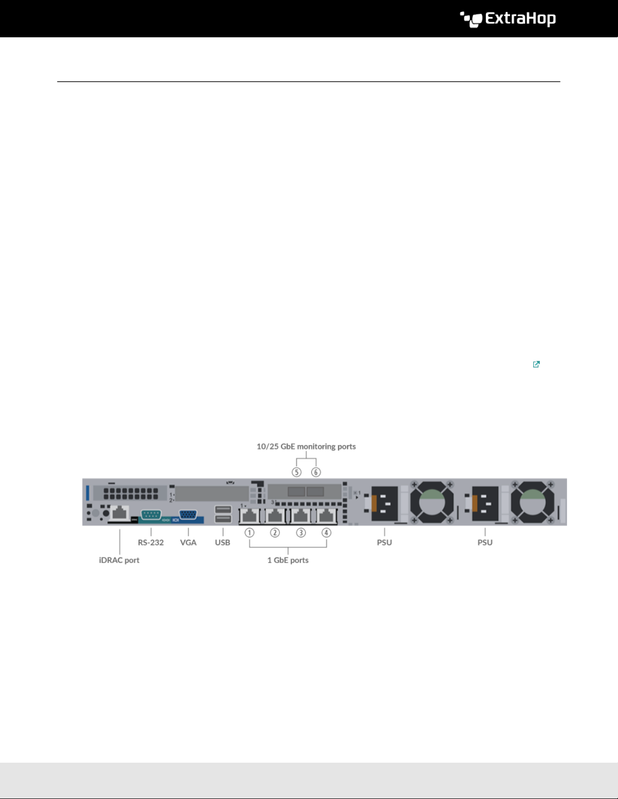
With the appropriate network cable, connect a monitoring port on the sensor to a network tap or
mirror port on the switch.
Important: The IDS 8280 requires a duplicate feed of the traffic that is sent to the packet
sensor.
Note: The link lights on the monitoring interface ports do not illuminate until you register the
ExtraHop sensor, recordstore, or packetstore with your product key.
4. Optional: Connect the iDRAC port.
To enable remote management of the sensor, connect your management network to the iDRAC port
with a network patch cable.
5. Install the front bezel.
You must install the front bezel if you want to configure the sensor through the LCD display.
Insert the USB connector on the right side of the bezel into the USB port on the front of the sensor.
Press and hold the release button on the left end of the bezel and push the bezel flush with the sensor
until it snaps into place.
6. Connect the power cords.
Connect the two supplied power cords to the power supplies on the back of the sensor, and then plug
the cords into a power outlet. If the sensor does not power on automatically, press the power button
on the front-right of the sensor.
Configure the management IP address
DHCP is enabled by default on the ExtraHop system. When you power on the system, interface 1 attempts
to acquire an IP address through DHCP. If successful, the IP address appears on the home screen of the
LCD.
If your network does not support DHCP, you can configure a static IP address through the LCD menu on
the front panel or through the command-line interface (CLI).
Important: We strongly recommend configuring a unique hostname . If the IP address on the
sensor is changed, the console can re-establish connection easily to the sensor by
hostname.
Configure a static IP address through the LCD
Complete the following steps to manually configure an IP address through the front bezel LCD controls.
1. Make sure that the default management interface is connected to the network and the link status is
active.
2. Press the select button (#) to begin.
3. Press the down arrow button to select Network, and then press the select button.
4. Press the down arrow to select Set static IP, and then press the select button.
5. Press the left or right arrows to select the first digit to change, and then press the up or down arrows
to change the digit to the desired number. Repeat this step for each digit you need to change. After
you configure the desired IP address, press the select button.
6. On the Network mask screen, press the left or right arrows to select the first digit to change, and
then press the up or down arrows to change the digit to the desired number. Repeat this step for each
digit you need to change. After you configure the desired network mask, press the select button.
7. On the Default gateway screen, press the left or right arrows to select the first digit to change, and
then press the up or down arrows to change the digit to the desired number. Repeat this step for each
digit you need to change. After you configure the desired default gateway, press the select button.

Deploy the IDS 8280 sensor 4
8. Confirm your modified network settings on the Settings saved screen, and then press any button
to return to the Network Menu.
9. Press the down arrow and scroll to Set DNS servers, and then press the select button.
10. Press the left or right arrows on the DNS1 screen to select the first digit to change, and then press the
up or down arrows to change the digit to the desired number. Repeat this step for each digit you need
to change, and then press the select button to continue to the DNS2 screen.
11. Configure a second DNS server.
12. Confirm the DNS settings on the Settings saved screen, and then press any button to return to the
Network Menu.
13. Press the down arrow twice until ← Back appears, and then press the select button.
14. Press the down arrow twice to select iDRAC. Configure the iDRAC DHCP, IP, mask, gateway, and DNS
in the same manner as the IP address.
15. Press the X button to return to the main menu.
Configure an IP address through the CLI
You can access the CLI by connecting a USB keyboard and SVGA monitor to the appliance or through an
RS-232 serial (null modem) cable and a terminal emulator program. Set the terminal emulator to 115200
baud with 8 data bits, no parity, 1 stop bit (8N1), and hardware flow control disabled.
1. Establish a connection to the ExtraHop system.
2. At the login prompt, type shell and then press ENTER.
3. At the password prompt, type the system serial number and then press ENTER. The serial number is
printed on a label on the back of the appliance. The serial number can also be found on the LCD display
on the front of the appliance in the Info section.
4. Enable privileged commands:
enable
5. At the password prompt, type the serial number, and then press ENTER.
6. Enter configuration mode:
configure
7. Enter the interface configuration mode:
interface
8. Run the ip command and specify the IP address and DNS settings in the following format: ip ipaddr
<ip_address> <netmask> <gateway> <dns_server>
For example:
ip ipaddr 10.10.2.14 255.255.0.0 10.10.1.253 10.10.1.254
9. Leave the interface configuration section:
exit
10. Save the running config file:
running_config save
11. Type y and then press ENTER.

Deploy the IDS 8280 sensor 5
Configure the system
Perform the following procedures to configure the IDS sensor.
1. Register your ExtraHop system .
2. Connect to ExtraHop Cloud Services .
3. Connect your console to the sensor.
• To connect to a self-managed console, see Connect an ExtraHop console to an ExtraHop sensor .
• To connect to Reveal(x) 360, see Connect to Reveal(x) 360 from self-managed sensors .
4. Join the IDS sensor to a site.
• For Reveal(x) Enterprise
1. On the Manage Connected Appliances page of the console, click Actions next to the IDS
sensor and then click Join Site from the Appliance Actions drop-down list.
2. From the Associated Site drop-down list, click the name of the site you want to join. You must
join a site that has the same network feed as the IDS sensor.
3. Click Join Site.
• For Reveal(x) 360
1. On the Reveal(x) 360 Administration > Sensors page, select the checkbox next to the name
of the IDS sensor.
2. On the Sensor Details pane, select the name of the site you want to join from the Associated
Site drop-down list. You must join a site that has the same network feed as the IDS sensor.
3. Click Join Site.
5. Complete the recommended procedures in the post-deployment checklist .
Table of contents