Extreme Networks BlackDiamond X8 Series User manual

BlackDiamond X8 Installation
Manual

Copyright ©

1Installing a BlackDiamond X8 Series
Chassis
Unpacking the Chassis
Checking Pre-Installation Requirements
Rack-Mounting the Chassis
Grounding the Chassis
Installing Power Supplies
Connecting Power Cords
Before you install the BlackDiamond X8 Chassis, read the information in Safety Information on page
29. Installing the BlackDiamond X8 chassis requires two people to maneuver the switch and attach
mounting hardware. Make sure there is adequate space behind the rack to provide access for installing
power supplies, cables, and modules.
The chassis should be installed before the modules and module blanks are installed. The chassis is
designed to fit into a standard 19-inch equipment rack. Optional mid-mount brackets allow you to
install the chassis in a mid-mount position.
Unpacking the Chassis
Use this procedure to safely remove the chassis from the box.
Caution
An unpopulated BlackDiamond X8 chassis weighs approximately 152 pounds (69 kg) as
shipped. Lifting the BlackDiamond X8 chassis safely requires a minimum of two people or
appropriate lifting equipment.
Note
Save all packaging, bolts, and washers, as well as the box and pallet, for future use in the
event that the chassis must be moved to another location or returned to Extreme Networks.
Refer to the illustrations printed on the BlackDiamond X8 shipping container and unpack the chassis
and accessories.
BlackDiamond X8 Installation Manual 3

1 Cut the straps around the box.
Figure 1: Unstrapping the Box
2 Slide the box up and off the chassis and interior packing foam.
Figure 2: Removing the Box
3 Remove the inside corner braces.
4 Remove the support brackets and boxed accessories and set them aside until you need them.
5 Lift off the upper packing foam.
Installing a BlackDiamond X8 Series Chassis
BlackDiamond X8 Installation Manual 4

6 Pull apart the keyed corner of the lower packing foam and remove the lower packing foam from
around the chassis.
Figure 3: Removing the Accessories and Foam
7 On each side, remove the restraining bolts from the shipping brackets at the front and middle of the
chassis.
Figure 4: Unbolting the Chassis
8 Remove all the fan trays, one at a time.
a Completely loosen the retaining screws at the top and bottom of the fan tray.
b Holding both handles, pull straight outward on the fan tray to disconnect the internal connector.
Installing a BlackDiamond X8 Series Chassis
BlackDiamond X8 Installation Manual 5

c Set the fan tray aside in a safe place.
Figure 5: Removing the Fan Trays
9 Open the accessory box and locate the four lifting handles.
Caution
Never use the handles on the fan assemblies to lift the chassis. The handles and the fan
assemblies are not designed to hold the weight of the chassis.
10 On each side of the chassis, set the pegs on the lifting handles into the mounting holes.
Figure 6: Preparing to Lift the Chassis from the Pallet
11 Verify that the following items are included in the shipping carton:
•BlackDiamond X8 chassis with installed front shipping cover and MM slot cover
•Power cord retainer
•Two 19-inch support brackets
Installing a BlackDiamond X8 Series Chassis
BlackDiamond X8 Installation Manual 6

Checking Pre-Installation Requirements
In addition to the support brackets that are shipped with the chassis, you need the following tools and
equipment to install a chassis:
•Mid-mount bracket kit (model number 48020, ordered separately from the chassis)
•# 2 Phillips screwdriver for attaching the mid-mount brackets to the middle of the chassis sides
•Rack-mount screws appropriate for your organization’s rack system, as follows:
•4 screws to attach each support bracket to the rack
•12 screws to secure the chassis in the rack
The screw size will vary based on your organization’s rack system; screws are not provided.
•Screwdriver appropriate for the selected rack mounting screws
•Chassis grounding materials as listed in Grounding the Chassis on page 10.
Rack-Mounting the Chassis
Note
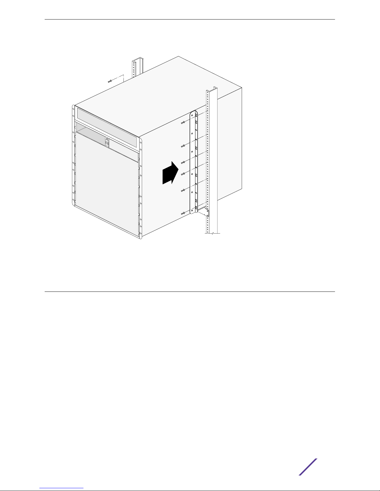
The chassis provides three possible locations on each side for the mid-mount brackets,
labeled A, B, and C. When you attach the brackets, make sure you use the same position on
each side.
A
B
C
ABC
Figure 7: Locating Possible Mid-mount Bracket Points
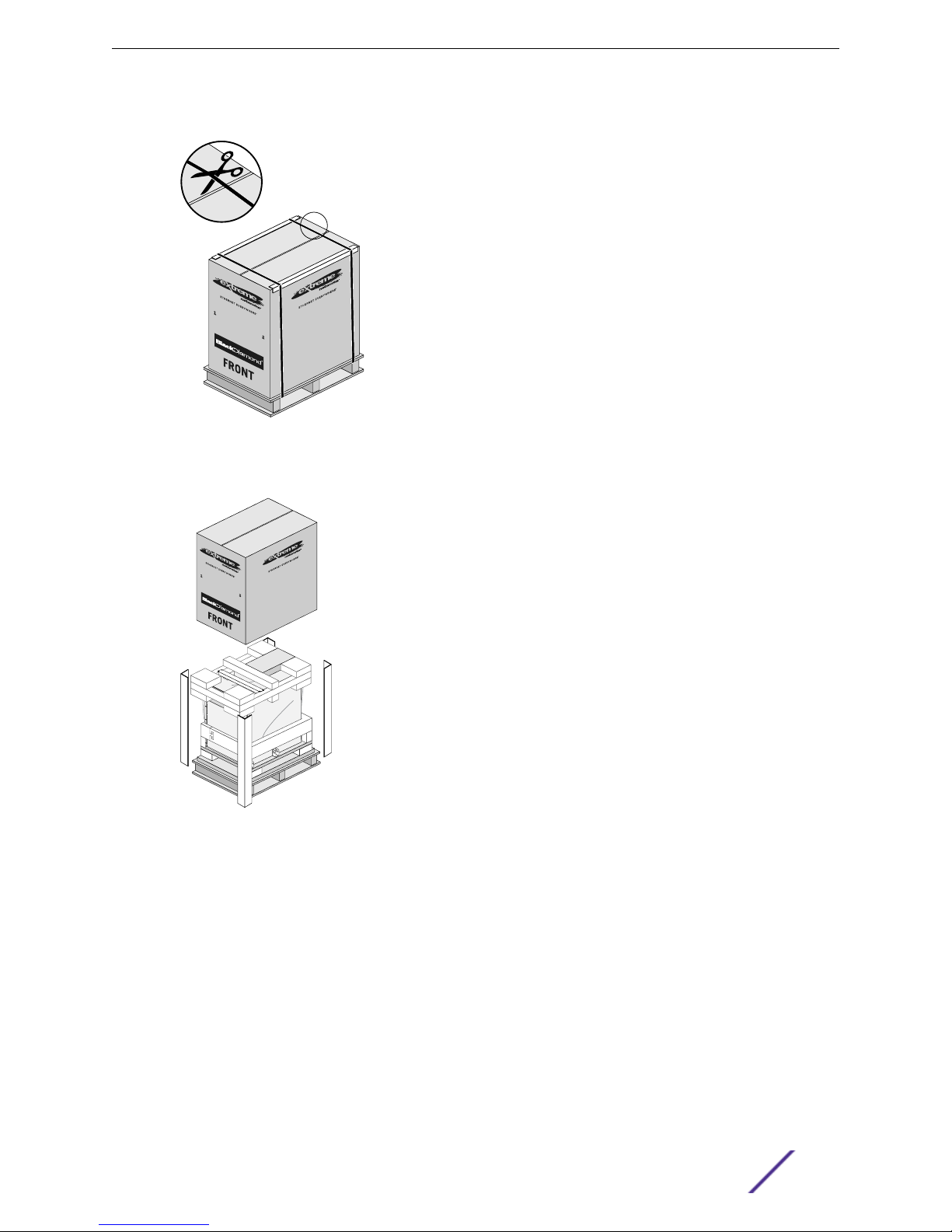
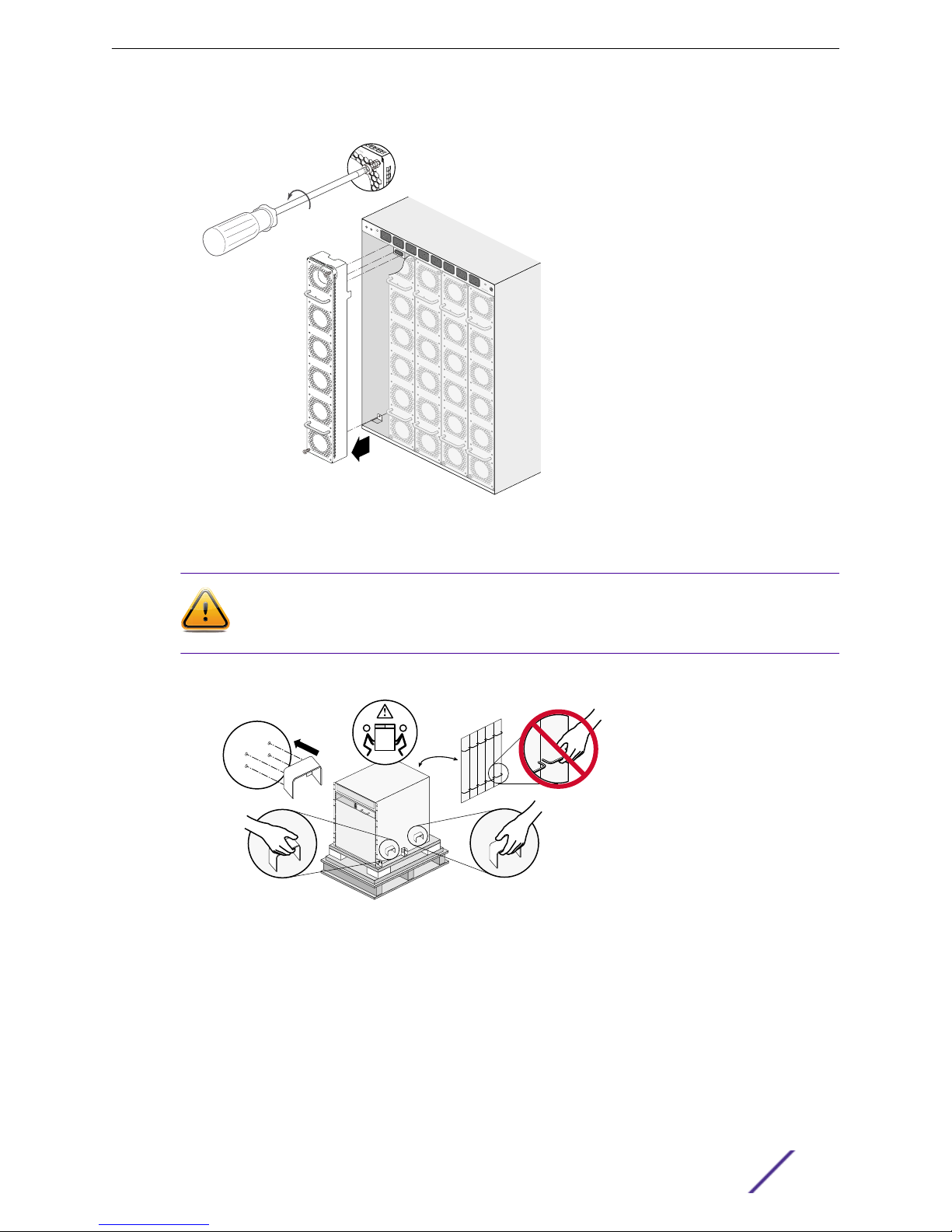
Before you install the chassis, verify that none of the modules or power supplies have been pre-
installed. Because of the weight of the chassis, it should be empty when you install it.
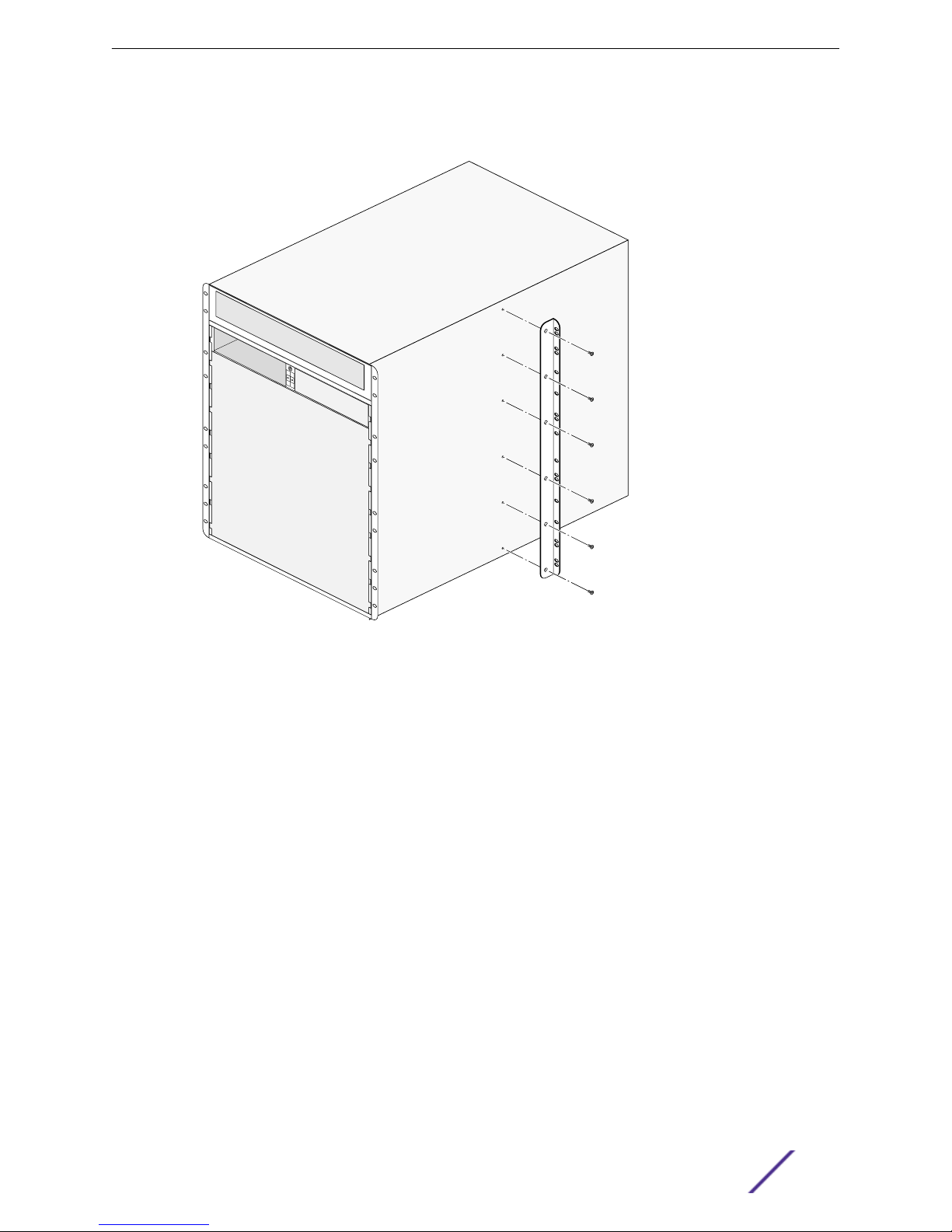
1 Attach mid-mount brackets to the sides of the chassis.
a On each side of the chassis, align a mid-mount brackets with its mounting holes on the chassis
sheet metal.
Installing a BlackDiamond X8 Series Chassis
BlackDiamond X8 Installation Manual 7

b Using a #2 Phillips screwdriver, insert and tighten the mounting screws to secure the bracket to
the chassis.
Figure 8: Attaching Mid-mount Brackets (position "C" shown)
2 Identify the rack location where the chassis will be installed.
Installing a BlackDiamond X8 Series Chassis
BlackDiamond X8 Installation Manual 8

3 Using four rack mounting screws, attach the support bracket to the equipment rack immediately
below the intended chassis location.
Screws are not provided.
To provide wider support for the chassis as you install it, you can attach the second support bracket
on the other side of the rack post.
Figure 9: Attaching the Support Bracket
4 If necessary, attach the lifting handles to each side of the chassis.
5 From the front of the rack, lift the back of the empty chassis onto the support bracket.
6 If attached, remove the lifting handles from both sides of the chassis.
7 Slowly guide the chassis into the equipment rack until the mounting brackets are flush against the
rack uprights.
8 Secure the chassis to the equipment rack using six rack mounting screws.
Screws are not provided.
Installing a BlackDiamond X8 Series Chassis
BlackDiamond X8 Installation Manual 9

9 Check to ensure screws are secure.
Figure 10: Securing the Chassis to the Rack
10 After the chassis is secured to the equipment rack, ground the chassis.
Grounding the Chassis
Although grounding the chassis is optional, it is recommended to do so. You must provide the following
materials to ground the chassis:
•Two 10-24 screws
•One copper, standard barrel 2-hole compression grounding lug with 0.63-inch hole spacing, type
LDC, equivalent to Panduit part number LCD4-14A-L or Thomas & Betts part number: LCN4-14
•# 14 AWG stranded copper wire
The rear panel of the chassis provides a grounding pad with threaded holes for attaching a ground
cable.
1 Identify the grounding pad on the back of the chassis.
Installing a BlackDiamond X8 Series Chassis
BlackDiamond X8 Installation Manual 10

Figure 11: Grounding Pad on the Chassis
1 = Grounding pad
2 Strip 0.5 inch (1.2 cm) of insulation from the stranded copper wire cable.
3 Insert the stripped wire into the cable lug.
4 Crimp the lug securely onto the cable.
5 Insert the screws through the lug and into the grounding pad on the back of the chassis.
6 Connect the other end of the wire to a known reliable earth ground point at your site.
After the chassis is grounded, install two or more power supplies.
Installing Power Supplies
You need the following tools and equipment to install an AC power supply:
•# 2 Phillips screwdriver.
•AC power cord rated for 100-120/200-240 VAC.
Warning
Be sure to read Safety Information on page 29 before you begin this procedure.
An AC power cord is not included with the chassis. You must obtain a power supply cord that meets
the requirements listed under Selecting Power Supply Cords on page 33.
1 Remove the power supply ventilation cover.
a Loosen the retaining screws at the top corners of the cover panel.
b Pull outward on the retaining screws to tilt the cover panel away from the front of the chassis.
Installing a BlackDiamond X8 Series Chassis
BlackDiamond X8 Installation Manual 11

c Lift the cover panel away from the chassis.
Figure 12: Removing the Power Supply Ventilation Cover
2 Identify the power supply bay where you will install the power supply.
Power supply bays are numbered from 1A to 8B. To establish an N+N redundant power
configuration, install power supplies in both the upper and lower rows.
Figure 13: Power Supply Bay Numbering on the Chassis
3 On the front of the power supply, push the release button to unlatch the insertion/ejector lever.
Installing a BlackDiamond X8 Series Chassis
BlackDiamond X8 Installation Manual 12

4 Slide the power supply into the chassis until the lever starts to engage.
Figure 14: Installing a Power Supply
5 Rotate the lever toward the front of the power supply to fully seat the power supply in the chassis.
6 Repeat steps to install other power supplies as required by your system configuration.
7 Replace the power supply ventilation cover.
a Set the lower edge of the cover in place so that the tabs on the edge fit into the matching slots
in the chassis frame.
b Rotate the top of the cover into place against the front of the chassis frame.
Installing a BlackDiamond X8 Series Chassis
BlackDiamond X8 Installation Manual 13

c Align and tighten the retaining screws.
Important
Do not operate the BlackDiamond X8 chassis without the power supply cover in place.
This cover is required to maintain proper EMI levels for the switch.
Figure 15: Installing the Power Supply Ventilation Cover
Connecting Power Cords
Warning
Be sure to read Safety Information on page 29 before you begin this procedure.
Warning
Do not apply power to the chassis until you have finished installing all modules, fan trays, and
module blanks. To apply power and access the chassis, see Applying Power and Accessing
the Chassis for the First Time on page 27
Use the following procedure to connect the AC power cords and the cord retainer.
Installing a BlackDiamond X8 Series Chassis
BlackDiamond X8 Installation Manual 14

1 At the back of the chassis, connect an AC power cord to the power input socket that corresponds to
each installed power supply.
Power input sockets are numbered from 1A to 8B from left to right, as you face the chassis back.
Figure 16: Numbers for Power Connectors
2 After all the power cords have been connected, set the power cord retainer over the power cord
connectors and against the back of the chassis.
3 Align and tighten the captive retaining screws on the power cord retainer.
Figure 17: Installing the AC Power Cord Retainer
Installing a BlackDiamond X8 Series Chassis
BlackDiamond X8 Installation Manual 15

2Installing BlackDiamond X8 Series
Modules
Initial System Installation and Module Installation Order
Required Tools
Installing Fabric Modules
Installing Management Modules
Installing I/O Modules
Applying Power and Accessing the Chassis for the First Time
The following sections describe how to install the modules and module blanks into the BlackDiamond
X8 chassis.
Note
The BlackDiamond X8 chassis should already be installed before you install any modules into
the chassis. See Installing a BlackDiamond X8 Series Chassis on page 3 for chassis installation
procedures.
Warning
Do not apply power to the chassis until you have finished installing all modules and module
blanks.
Initial System Installation and Module Installation Order
After the chassis is installed, you can install the modules and module blanks. For an initial system
installation, the recommended order for installing modules and module blanks into the chassis is:
1 Install all management modules (MMs). See Installing Management Modules on page 20.
2 Install MM blanks in any unoccupied slot. See Installing a Management Module Blank on page 22.
3 Install all fabric modules (FMs). See Installing Fabric Modules on page 17.
4 Install I/O modules. See Installing I/O Modules on page 22.
5 Install I/O blanks in any unoccupied slot. See Installing I/O Module Blanks on page 24.
6 Apply power to the chassis. See Applying Power and Accessing the Chassis for the First Time on
page 27.
Required Tools
You need the following tools and equipment to install modules:
•ESD-preventive wrist strap
•#2 Phillips screwdriver for the retaining screws on the fan tray and locking screws on management
and I/O modules
BlackDiamond X8 Installation Manual 16

•5/16-inch flat-tip screwdriver for the retaining screws on the fabric module
Installing Fabric Modules
Install all the fabric modules before you install I/O modules.
The slots for fabric modules are numbered 1 through 4, from left to right. If you are installing only three
fabric modules, use slots 1 through 3.
1 Attach the ESD-preventive wrist strap to your bare wrist.
2 If it is not already connected, connect the metal end to the receptacle at the right of the power input
connectors.
3 Remove the fan tray from each location where you will install a fabric module.
Figure 18: Removing a Fan Tray
4 Install each fabric module.
Installing BlackDiamond X8 Series Modules
BlackDiamond X8 Installation Manual 17

a Loosen the screws on the insertion/extraction levers and open the levers.
Caution
To prevent ESD damage, hold the module by the metal rail and front panel only. Never
touch the components on the PCB or the pins on any of the connectors.
Figure 19: Installing a Fabric Module
b Align the circuit board with the guides at the top and bottom of the chassis and slide the module
into the chassis.
Installing BlackDiamond X8 Series Modules
BlackDiamond X8 Installation Manual 18

c When the levers start to engage, push them toward the module to seat the module in the
chassis.
d Align and tighten the retaining screws to fasten the module in place.
Figure 20: Securing a Fabric Module
5 Repeat these steps to install additional fabric modules.
6 Re-install the removed fan trays.
a Set each fan tray into the chassis and push it firmly into place.
Installing BlackDiamond X8 Series Modules
BlackDiamond X8 Installation Manual 19

b Align and tighten the retaining screws.
Figure 21: Installing a Fan Tray
Installing Management Modules
Slots for management modules are labeled A and B. Install the first management module in slot A.
1 Attach the ESD-preventive wrist strap to your bare wrist.
2 If it is not already connected, connect the metal end to the receptacle between the management
module slots.
3 If necessary, remove the cover from the unoccupied slot.
4 Remove the module from the antistatic packaging.
Caution
To prevent ESD damage, hold the module by the metal rail and front panel only. Never
touch the components on the PCB or the pins on any of the connectors.
5 Verify that the injector/ejector handle is in the open position.
Keep the injector/ejector handle in the open position as you slide the module into the chassis slot.
6 Carefully slide the module into the slot (starting with slot A) until the injector/ejector handle
engages the edge of the chassis and begins to rotate toward the module.
Installing BlackDiamond X8 Series Modules
BlackDiamond X8 Installation Manual 20
Other manuals for BlackDiamond X8 Series
3
Table of contents
Other Extreme Networks Chassis manuals