2
XTP II CrossPoint Series • Setup Guide (Continued)
Mounting
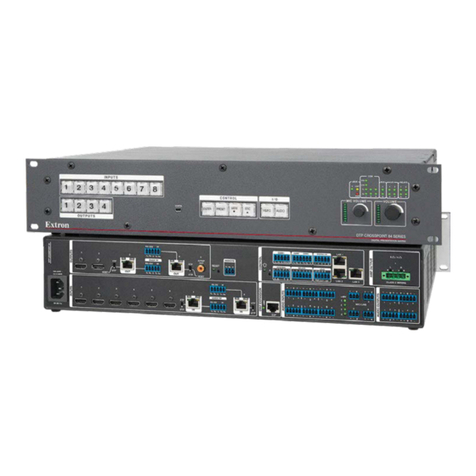
Use screws on each side of the matrix switcher to attach the front panel to a rack (see the XTP II CrossPoint Series User Guide at
www.extron.com for more mounting information).
Rear Panel Features
CRemote RS-232 and RS-422 connector (see figure 1 on the previous page)
— For RS-232 or RS-422 serial control of the matrix switcher, connect a host
device to the 9-pin HD connector. Wire the connector for RS-232 or RS-422
communication as shown to the right.
DEthernet LAN connector — For 10/100BASE-T, half duplex or full duplex
Ethernet control of the matrix switcher, connect a host device, LAN, or WAN
to the RJ-45 connector with crossover or patch cable.
Default protocol for this port:
• IP address = 192.168.254.254
• Subnet mask = 255.255.0.0
• Gateway address = 0.0.0.0
EReset button and LED — Hold the recessed reset button in to perform various resets (see the XTP II CrossPoint Series User
Guide for more information about reset modes).
FPower connector — Connect a power source to the AC power connector.
• AC Power — Connect a 100 VAC to 240 VAC, 50-60 Hz power source to this connector with a standard
IEC power cord.
• Attached AC power (XTP II CrossPoint 6400 only)
• North America — Connect the power cord into a NEMA L6-20 220VAC, 60 Hz power outlet.
• Other regions — Have a licensed electrician install a 200-240 VAC power connector. Then, connect
the power cord into a 200-240 VAC, 50-60 Hz power outlet. Ensure the wiring is in accordance with
electrical codes.
ATTENTION: Extron recommends that this procedure be performed by a licensed electrician only (see the
XTP II CrossPoint Series User Guide).
Board Connections
The available connectors depend on the board models. The following connector information represents potential connectors
included with input and output boards.
XTP interconnection connectors
XTP twisted pair, 4K twisted pair, and fiber boards may include the following connectors:
• XTP twisted pair input connectors — Connect a shielded twisted pair cable between the XTP input connector on the input
board and the XTP output connector on an XTP twisted pair device (see Twisted pair recommendations on the next page).
• XTP twisted pair output connectors — Connect a shielded twisted pair cable between the XTP output connector on the
output board and the XTP input connector on an XTP twisted pair device (see Twisted pair recommendations).
• XTP fiber input connectors — Connect a fiber optic cable between the XTP input connector on the input board and the XTP
output connector on an XTP fiber device (see Fiber communication on page 4).
• XTP fiber output connectors — Connect a fiber optic cable between the XTP output connector on the output board and the
XTP input connector on an XTP fiber device (see Fiber communication on page 4).
• Pass-through LAN connectors — Connect a control device or device to control to the RJ-45 connector with crossover or
patch cable to pass 10/100BASE-T Ethernet communication.
• RS-232 and IR Over XTP — To pass bidirectional serial or infrared signals to a control
device or device to control, connect the device to the RS-232 and IR Over XTP connector.
Wire the connector as shown to the right.
North America
Hot Y: Hot
G
X
Y
Pin RS-232 RS-422
RS-232 FunctionPin Function
1
2
3
4
5
6
7
8
9
—
TX
RX
—
Gnd
—
—
—
—
Not used
Transmit data
Receive data
Not used
Signal ground
Not used
Not used
Not used
Not used
—
TX–
RX–
—
Gnd
—
RX+
TX+
—
Not used
Transmit data (–)
Receive data (–)
Not used
Signal ground
Not used
Receive data (+)
Transmit data (+)
Not used
RS-422
1
5
1
2 Tx Tx-
3 Rx Rx-
4
5 Gnd Gnd
6
7 Rx+
8 Tx+
9
