SD - 1000
Max 1500ml/h
40 ~ 200°C
±1°C
Digital display 1 ~ 250°C
Digital display 1 ~ 250°C
Digital display 0.2 ~ 0.95m3/min
Digital display 10 ~ 300 kPa
PID control, zero cross output
Pt 100Ω
Pt 100Ω
3 kW, SUS 316
0 ~ 10 mV (at 50 ~ 250 °C)
0 ~ 10 mV (at 50 ~ 250 °C)
0 ~ 10 mV (at 0 ~ 1 m3/min)
150 ~ 1700 ml/h (Usable tubing : ID3.15mm x OD5.2mm
700W x 620D x 1500H mm
Pressure : 294 kPa (3 kg/cm2), Flow rate : 25L/min or more
OD 50 mm
Double fluid nozzle (outlet size for sample : ø0.71mm)
Jet cleaner
Automatic (Interval timer setting : OFF or 1 ~ 20min. / Manual
Temperature alarm, Sensor alarm, Upper limit alarm for outlet temperature,
Air flow alarm, Heater alarm, SSR alarm, Pump line pressure alarm,
Spraying pressure alarm)
49 ~ 245 kPa (0.5 ~ 2.5 kg/cm2)
5 ~ 35°C
Excess current, power breaker, over temperature protector, manual recovering
after power failure
100 ~ 1000 rpm ( Rotation speed is changeable by volume knob)
0.2 ~ 0.75 m3/min ( Flow rate is changeable by control knob)
21 A, 4.2 kVA
AC 200 V Single phase, 50/60 Hz
110 kg
ID4 mm x OD6 mm (Soft urethane tube union)
−3−
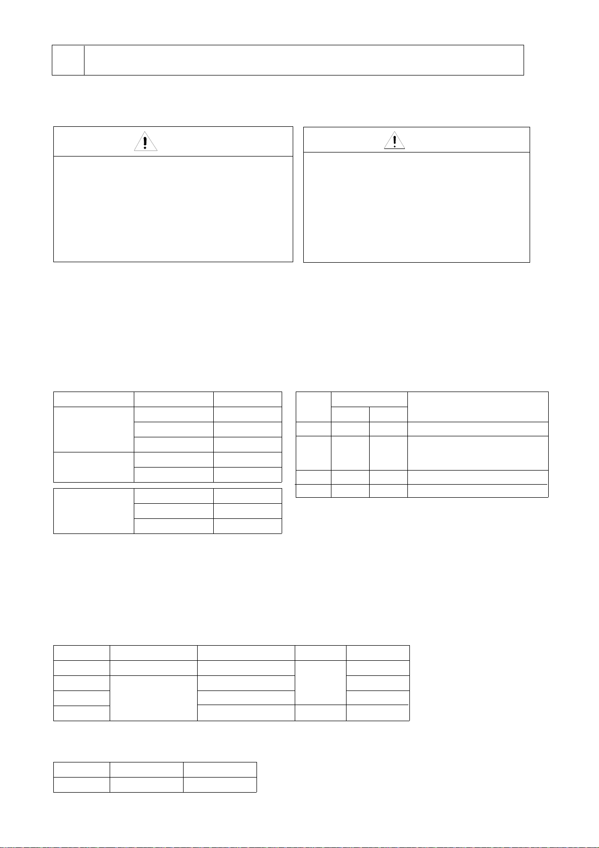
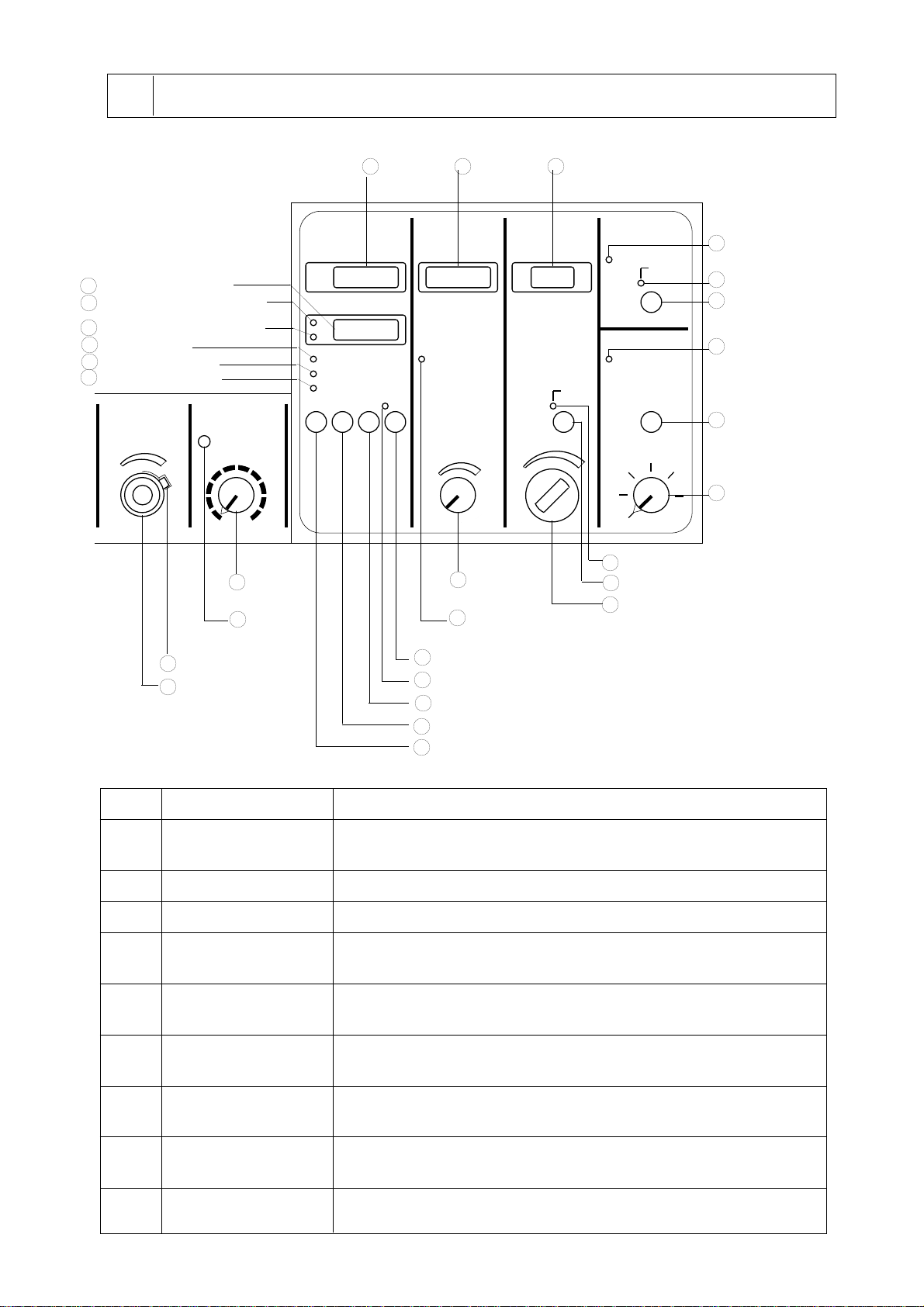
2-3 Specifications
Spray dryer
Model
Evaporating rate
Inlet temp. control range
Inlet temp. control accuracy
Drying air flow rate control range
Spraying air press. control range
Flow rate control range
Stirring speed control range of
source liquid
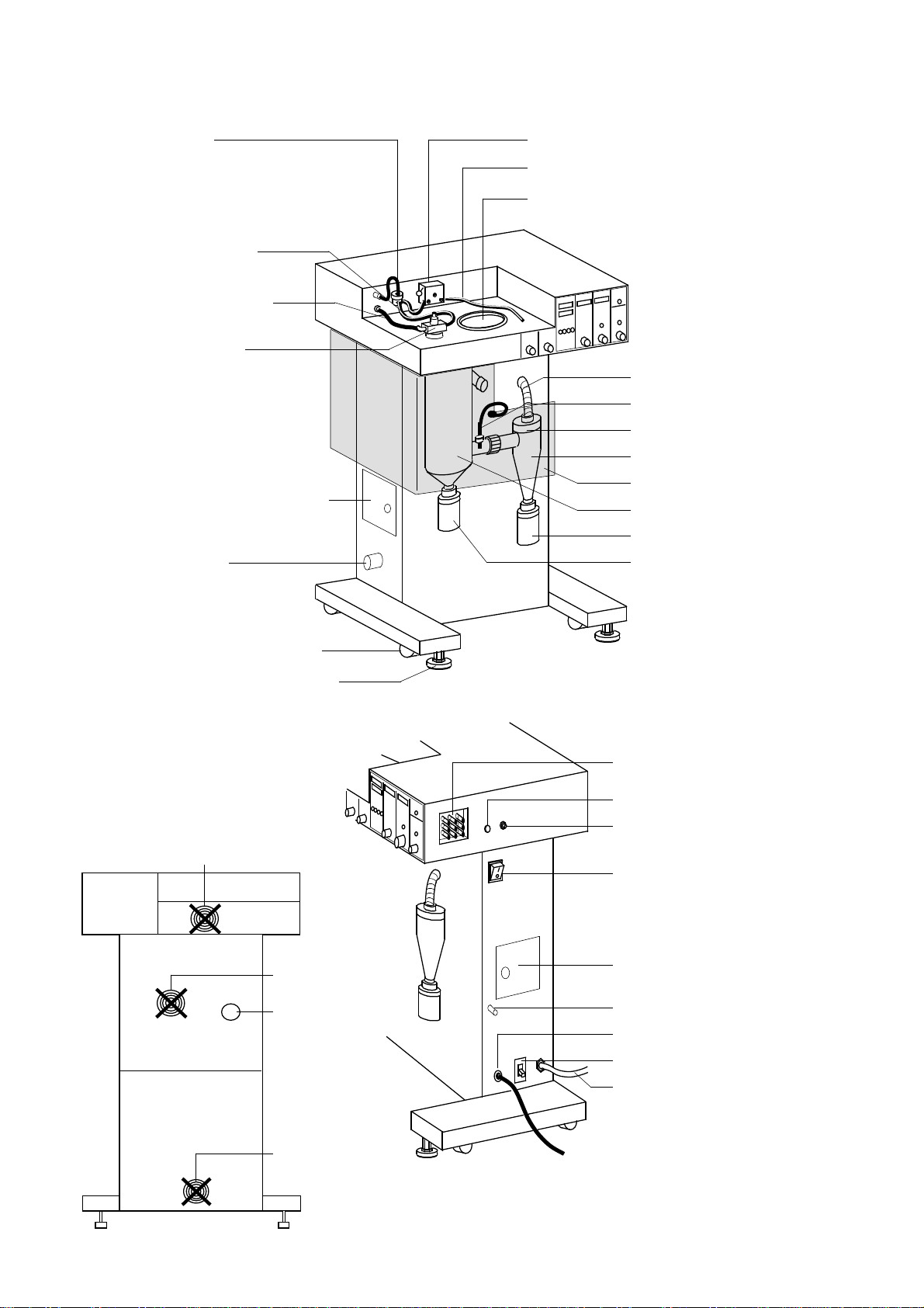
Inlet temperature display
Outlet temperature display
Drying air volume display
Spraying pressure display
Temperature controller
Inlet temperature sensor
Outlet temperature sensor
Heater wattage and material
Inlet temp. recorder output
Outlet temp. recorder output
Drying air volume output
Spray nozzle
Spraying air line
Automatic cleaning system
Safety feature
Alarm function
Spraying air connection port size
Spraying air pressure
Exhaust port size
Ambient temperature range
Overall dimensions
Net weight
Power consumption
Power source