EYELA FDU-2200 User manual

R00
取扱説明書
Instruction
Manual
Freeze dryer
FDU-2200
This instruction manual is designed to use the product efficiently and safely.
Please keep this manual in a place easily accessible to every user.
Be sure to read “Safety precautions
carefully before use.
IMPORTANT
Tokyo Rikakikai Co., Ltd.

Safety precautions
1. Signal word for warning
Therefore, this manual categorizes the level of
importance and danger as below with alert mark and
signal word. Please follow the instructions and use
the product safely.
Wrong operation of the product may cause you
physical injury. However, if you have proper
information before use, you can avoid almost
all these troubles.
Alert mark
Signal word Definition
Mishandling the product may cause users serious personal injury or loss of life.
WARNING
Mishandling the product may injure users or cause property damage.
CAUTION
Though we are trying to look into conceivable risk of using the product, it is very difficult for us to
expect all. It means that all the instructions in this manual do not cover all the potential risks that may
be caused by the product. However, if you follow the instructions, you surely can handle and operate
the products safely. Please use extreme care when handling this product and try to prevent all the
potential accidents and mechanical failures.

2. Warning display on the product
For highly priority danger, warning label is attached
on the machine body. The position of the label is as below.
Please read the instructions carefully whenever using the machine.
※If you have any trouble reading the label
because of damage and etc., please replace
with new one. Contact us if your
require new label.
CAUTION
Do not touch
the cooling fin
with bare hands.

Thank you for choosing the product of
Introduction
This instruction manual describes the procedure of installation,
operation, troubleshooting, maintenance, check up, and disposal
of Freeze dryer, FDU-2200.
Please read this manual carefully before use.
Contents
1.For safety use
Items contained
in your carton
4 – 4 Utility connection
5.Operation
5 – 1 Preparation
5 – 2 How to operate
6.Troubleshooting
7.Maintenance・checking
7 – 1 How to replace consumable parts
7 ‐ 2 Operation test for electric leakage breaker
7 ‐ 3 Replacing fuse
7 ‐ 4 Cleaning and caring the product
8.Disposla of the product
9.After-sales service
2.Ouline of the product
2 – 1 Use application 2
2 – 2 Specification
2 – 3 Data on the product(Reference)
2 – 4 Options
2 – 5 Name of each part
3.Name and functions of operating portion
3 – 1 Control panel
3 – 2 Safety functions 12
4.Installation
4 – 1 Installation environment
4 – 2 Installation condition
1
2
3
9
4
8
Please check the type and the quantity of every part.
14
14
16
17
30
31
31
18
27
33
34
32
Filter for leaking
1Instruction Manual
7
1
Main unit
1
1
Fuse
2
2Recorder output cable
3
1
Filter for leaking
4
4
Caster holder
5
1
Trap barrier
6
QuantityName
No.
4 – 3 Installation 15
Caster holder Trap barrier

For safety use
1
This product is not designed with explosion-proof structure.
Use extreme care when handling it.
Solvent that can not be trapped may be vacuumed into the
vacuum pump, which may cause a fire or explosion.
Use extreme care when drying sample that includes
inflammable substance, such as organic solvent.
WARNING
Cooling fin
Do not touch the cooling fin with bare hands during maintenance work.
Edgy fin may cut your hands.
Do not touch the cooling fin with bare hands.
CAUTION
●Preliminary freeze the sample container.
●Change the oil in the vacuum pump regularly.
‑1‑

Outline of the product
2
2-1 Use application
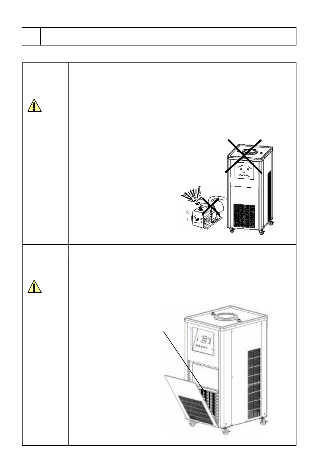
Do not remodel the product.
Do not use it out of intended application.
Remodeling or using the product out of intended
Application may cause electric shock or
malfunction.
WARNING This product can be used for drying dilutional solution
such as protein, enzyme or extraction solution of biological
sample, or biogenic sample such as urine, blood serum and
etc.
2-2 Specification
Pirani gauge
Digital display 0.0〜533.3Pa
Recorder output Trap temperature 1℃/1mV Vacuum degree 1Pa/1mV
Voltage
Rated supply AC100V±10%、50/60Hz
Features
C
O
N
F
I
G
.
Model
Refrigerator(Output)
Service outlet
S
P
E
C
.
Mass
Product name
F
U
N
C
I
T
I
O
N
S
Refrigerant
Range of available ambient temperature
Freeze dryer
FDU‑2200
Trap cooling temp.
Dehumidifying amount
Trap defrosting function
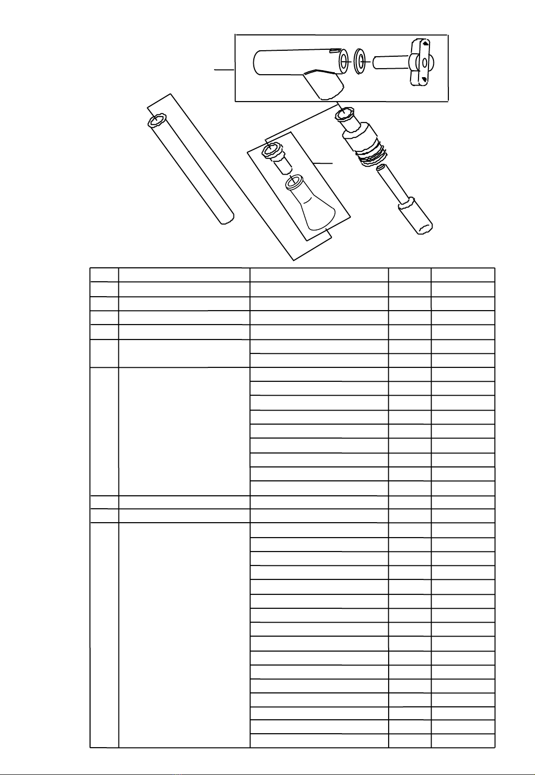
Trap measurement (mm) material
Vacuum gauge
Defrosting by hot gas
153(Bore diameter)×225(Height)、SUS304
External measurement(mm)
−80℃
1 ℓ/Time
400W × 2
5〜35℃
450(W)×550(D)×935(H)
Approx.67kg
Cooling system Cooled into drum-shaped container
※1
Required displacement of vacuum
pump More 50/60L/min(50/60Hz)(option)
Other functions Vacuum pump control, display of the availability of freeze drying,
display of vacuum pump operation time,
Stop watch function, selecting power recover function,
Detecting abnormal vacuum degree(fixed value), Protection timer for
refrigerator
Displaying accuracy at 0.4〜4.0Pa ±2.0Pa
at 4.1〜10.0Pa ±3.0Pa
at 10.1〜15.0Pa ±4.0Pa
at 15.1〜40.0Pa ±7.0Pa
HFC(R404A)(Primary refrigerator)+R23(Secondary refrigerator)
For vacuum pump(Max.6A )For dry chamber(Max.2A )
AC100V 12A
※2
※3
※1.Measured in the following condition; ambient temperature:20℃, NO load
※2.Protruding portion is not included.
※3.Capacty of service outlet is not included.
‑2‐

2-3 Data on the product(Reference)
・Attached 4 pear-shaped flasks (capacity:1ℓ) containing 250g of water to
the trap and calculated back the sublimation from the remaining amount of flask after
elapsing designated length of time.
Condition ・AC100V,50Hz
・Ambient temperature 20℃
(1)Data on sublimation speed
Sublimation
amount(g) 900
1000
800
700
600
500
400
300
200
100
0
01234567891011
Time(h)
・Sublimation speed differs depending on room temperature, capacity and the shape of sample’s
container (pear-shaped flask and freeze dry bottle and etc.), type and quantity of sample, and
the condition of preliminary frozen sample.
Condition ・AC100V,50Hz
・Ambient temperature 20℃
(2)Data on trap temperature when subliming sample
20
30
Temperature(℃)
Room temperature
10
0
‑10
‑20
‑30
‑40
‑50 Displaying temperature of the unit
Recorder output)
‑60
‑70
‑80
‑3‑
・Data on trap temperature when subliming sample differs depending on room temperature,
capacity and the shape of sample’s container (pear-shaped flask and freeze dry bottle and etc.),
type and quantity of sample, and the condition of preliminary frozen sample.
‑90
The beginning of trap
012345678910
Time(h)

2-4 Options
‑4‑
■Test tube, ampoule bottle and manifold for vial container
Stainless T-shaped manifold with 12 (PMH-12) / 24 (PMH-24)
inlets for being applied sample. Samples in each inlet can be
freeze dried simultaneously.
※When using test tube or ampoule container,
appropriate adapter is required.
Model Catalogue No.
PMH‑24 119860
PMH‑12
PMH‑24
This option can be secured to the main unit of
FDU-2200. With this base, the main unit can be
moved with connecting vacuum pump.
(This optional accessory is available only for FDU-2200).
Secures Manifold (option) to the main unit of FDU-2200.
(This optional accessory is available only for FDU-2200).
209540FDU‑CRAMP2
Catalogue No.Model
FDU‑BASE
PMH‑8
■Manifold for flask
Stainless T-shaped manifold with four (PMH-4) /
eight (PMH-8) inlets for being applied sample.
Samples in each inlet can be freeze dried simultaneously.
Model Catalogue No.
PMH‑4
PMH‑8
119820
119830 PMH‑4
PMH‑12 119840
■Bearing for acrylic base
FDU‑CRAMP2
■Base for vacuum pump
209540FDU‑BASE
Catalogue No.
Model
DRC‑3L
■Airtight system dry chamber
Airtight preservation can be performed at the
top shelf after completing freeze drying. Other
shelves can be used as dry chamber.
BSC‑2L
Model Catalogue No.
BSC‑3L 119810
119790
BSC‑3L
BSC‑2L
■Dry chamber
Freeze drying can be performed in vial container
and petri dish.
DRC‑1N DRC‑2L
119730
DRC‑1N
DRC‑2L 119750
Model Catalogue No.
DRC‑3L 119770

⑧
⑨
⑦
②③
①
■Stopcock B, test tube, ampoule container
and etc.
④
⑥
⑤
Stopcock B 119930
11
Vacuum stopcock body B 144480
21
Liner B 143960
10
Vacuum cock B
B‑type Adapter for test tube 120510
1
10
7
Specification Catalogue No.
Product name
No. Qty
3
144490
Forφ8
Forφ6
120520
120530
5
120210
Ampoule container Pear‑shaped (1mℓ)
120220
20
20
1
1
4
5
6
Adapter for ampoule
container
Pencil‑shaped round bottom(1mℓ)
Pencil‑shaped flat bottom(1mℓ)
Flat bottom(2mℓ)120230
20
20
120221
Flat bottom(5mℓ)120240
20
Flat bottom(10mℓ)
Round bottom(2mℓ)
120250
120260
10
20
Round bottom(5mℓ)120270
20
Round bottom(10mℓ)120280
Sealing 145610
143970
143980
143990
144000
Test tube with rim φ10×75(3mℓ)
φ12×75(4mℓ)
φ12×90(5mℓ)
φ12×105(6mℓ)
φ12×120(7mℓ)
φ13×75(5mℓ)
φ13×90(6mℓ)
144010
144020
144030
144040
100
100
100
100
100
100
100
100
1
8
9
φ13×100(7mℓ)
φ15×85(8mℓ)144050
100
φ15×105(10mℓ)144060
100
φ16.5×165(20mℓ)
φ18×165(24mℓ)144100
144090
50
50
φ15×150(15mℓ)144070
50
φ16.5×10⁵(12mℓ)144080
100
φ18×180(27mℓ)
φ21×200(42mℓ)
144110
144120
50
50
‑5‑

■Stopcock A, Freeze drying container, flask and etc.
‑6‑
⑳
⑪
⑩
⑫
⑬
⑭
⑮
⑯
⑲
22
21
24
Flask for sample 50mℓ
100mℓ
200mℓ
300mℓ
500mℓ
1000mℓ
116140
116150
116160
116170
116180
116190
1
1
1
1
1
1
Specification Cat.No.
Product name
No. Qty
Stopcock A
Vacuum stopcock body A
Liner A
Vacuum stopcock A
Adapter for flask
10
11
12
13
14
15
119920
144460
143950
144470
120470
144500
1
1
10
1
1
1
・
⑮
⑧
⑰
23
T 29
S
T 24
S
T 29
S
T 29
S
T 29
S
T 29
S
T 29
S
T 29
S

40mℓφ45 (bore diameter) 120050
1
1
22
Specification Cat. No.
Product name
No.
50mℓ
100mℓ
200mℓ
300mℓ
500mℓ
1000mℓ
116220
116230
116240
116250
116260
116270
Qty
1
1
1
1
1
1
Flask for sample T 24
S
T 24
S
T 24
S
T 24
S
T 24
S
T 24
S
15
A‑shaped adapter for test tube
16 120500
1
2120460
17 Adapter for freeze drying
container 3
18 120450
120020
‑7‑
1200mℓΦ105 (Bore diameter) 120090
1
119940
119950
1
1
23
Freeze drying container
80mℓΦ45 (Bore diameter)
120mℓΦ70 (Bore diameter)
150mℓΦ70 (Bore diameter) 120130
1
300mℓΦ70 (Bore diameter) 120140
1
600mℓΦ105 (Bore diameter) 120070
1
900mℓΦ105 (Bore diameter) 120080
1
120060
120120
1
A set of freeze drying
container
40mℓ
80mℓ
120mℓ
150mℓ
300mℓ
600mℓ
900mℓ
1200mℓ
For φ70 120・150・300mℓ
For φ105 600・900・1200mℓ
Cap (for freeze drying
container)
For φ45 40・80mℓ1
19
1120030
1120040
Filter holder 120100
20 1
120110
Filter 1
100 sheet/1 box
21
119960
1
119970
1
119980
1
119990
1
120000
1
120010
1
1
Mu
24 120490
ltiple connection adapter
■Cover with nozzle
This cover is used as a trap.
However, it is available within the range of specified
vacuum degree (0〜533Pa) of FDU-2200.
209520ー
Catalogue No.Model

2-5 Name of each part
Trap barrier
Cold trap
Rubber tray
Control panel
Airflow cover
Caster with stopper
(4 wheels both on front and back)
Tube Hose joint
※In case of using nitrogen purge (when using it under plus pressure),
remove hose joint with vibe wrench and etc.
Then, screw pipe for nitrogen purge directly into socket.
Diameter of screw:G1/4
Socket
※Insert it into tube
Drain stopcock(drain hose)
Fuse holder
Outlet for vacuum pump
(6A)
Recorder output(vacuum degree)
Recorder output
(Trap temperature)
Outlet for dry chamber (Max2A)
Filter for leaking
Leak nozzle
End connection for vacuum pump
(External diameter φ17.3)
‑8‑

Name and functions of each part
3
3-1 Control panel
⑪
Trap
temp. ℃
Vacuum
Pa
Timer hour
Mode1
Mode2
Freeze Drying
Refrigerator
Alarm
Ref.Alarm
▼
▲Display
Set
Reset
Run
Stop
Timer
hour.min
⑩Trap temperature indicator
⑫
⑬Lamp for Freeze drying
(Displays the availability)
⑭Refrigerator
lamp
⑮Alarm lamp
⑯
Alarm lamp
For refrigerator
⑰Lamp for displaying timer
mode
⑱Timer mode selecting
switch
⑲Set key switch
⑳Lamp for set key
21
Timer switch
22
Def
Auto
Refrigerator
Run
Stop
②Automatic/Manual
③Lamp for automatic
operation
④Refrigerator switch
⑤Lamp for refrigerator
⑦Switch lamp for
vacuum pump
⑥
Vacuum pump
switch
Vacuum
pump
⑧Defrosting switch
⑨Lamp for defrosting switch
①Power switch
(Electric leakage breaker)
Timer lamp
23 Timer reset
switch
Gauge
Timer indicator
Vacuum degree indicator
selecting switch
‑9‑

Name Function
No.
①
③
②
⑤
⑨
⑧
④
⑦
⑥
⑩
⑪
⑫
⑬
⑭
⑮
⑯
⑰
⑱
⑲
⑳
Power switch Turns on and off the power source (electric leakage breaker)
‑10‑
Lamp for automatic operation
Automatic / Manual
selecting switch
Lamp for refrigerator switch
Lamp for vacuum pump
switch lamp
Refrigerator switch
Vacuum pump switch
Defrosting switch
(ON・OFF Press longer than 3 sec.)
Lamp for defrosting switch
Trap temperature indicator
Vacuum degree indicator
Timer indicator
Lamp for freeze drying
(display the availability)
Refrigerator lamp
Alarm lamp
Alarm lamp for refrigerator
Lamp for displaying timer
mode
Timer mode selecting switch
Set key
Lamp for set key
Lights up when turning on refrigerator switch.
Refrigerator starts working when turning this switch on in automatic
/manual operation. In automatic operation, vacuum pimp starts operating
when trap temperature reaches at -30℃. All the operations get stopped
when turning this switch off.
Selects Automatic or Manual operation.
Lights up when automatic operation is selected.
When turning on this switch in manual operation,
outlet for vacuum pump is supplied power(refer to 5-1. Preparation).
Plug mains connector for vacuum pump into outlet.
In automatic operation, this switch stops only the operation of vacuum pump.
The mode of operation changes to manual when turning off this switch.
Lights up when turning on vacuum pump switch, or when vacuum
pump starts working in automatic operation.
When turning on this switch after the termination of freeze drying,
defrosting on the cooling zone gets started. In this case, vacuum pump is
stopped automatically.
Lights up when turning on defrosting switch and turns off a light
when defrosting is terminated.
Displays the trap temperature of trap cooling zone.
Displays measured vacuum degree of the unit.
Displays measured temperature by selecting mode.
Lights up when trap temperature and vacuum degree reach at your desired
condition. Sample container can be attached when this lamp lights up.
Lights up while refrigerator works.
Lights up when vacuum degree is abnormal or vacuum sensor
or temperature sensor has malfunction, or power failure alarm occurs.
Lights up when over load relay of refrigerator works.
Lights up and displays the mode of measured timer time.
Mode1:Displays the operation time of vacuum pump.
Mode2:Displays measured time of stop watch function.
Selects displaying time of timer(Mode1・2).
This switch is used for inputting the value for power failure time
(factory default value is 5 min.) , when selecting power recovery function.
Also, it is used when stopping alarm lamp, display and buzzer.
Lights up when turning on Set key.

No. Name Function
Resets the displaying time for timer if you press this switch for
longer than 5 seconds.
Timer lamp
Timer reset switch
Timer switch Turns on and off stop watch function of Timer Mode 2.
Lights up while stop watch function of Timer Mode 2 works.
21
22
23
CAUTION
※1 When turning off the unit by vacuum pump switch or refrigerator switch or refrigerator switch or
timer switch, press each switch longer than 3 seconds.
※2 When turning on/off the unit by defrosting switch, press the switch for longer than 3 seconds.
※3 When resetting the displaying time for timer, press timer reset switch for longer than 5 seconds.
‑11‑

3-2 Safety functions
This product is equipped with the safety functions and alarm displaying functions as below.
Safety functions
・This function stops controlling
by detecting malfunction of temperature
controller or noise.
・Ambient temperature exceeds 35℃.
・Influence of noise
Safety device Operation Reasons why the device operates
Electric leakage
breaker Turns OFF the power supply. ・Electric leakage occurs.
Or excess current flows.
Over load relay
retaining circuit
for refrigerator
Lights up alarm lamp and blinks
trap temperature, and stops the
operation of refrigerator while
refrigerator performs over load
(over heat) operation.
・Refrigerator performs over load start up
(operation).
・Ambient temperature exceeds 35℃.
・Dirt adheres air filter.
・Fan of refrigerator does nit work.
・Supply voltage is too low.
Self-analysis
function of
controlling base
plate
Controlling base plate is in abnormal
condition and buzzer beeps
continuously, and stops controlling.
Safety valve for
vacuum pump
(Leak valve)
Safety valve opens and vacuum
system releases air, which prevents oil
in vacuum pump from flowing into
vacuum system.
Safety valve works when vacuum pump
stops operation because of power failure
or other accidents during experiment.
Safety valve works when freeze drying is
terminated and automatic operation is
stopped, or when vacuum pump is
stopped in manual operation during
defrosting.
Fuse for service
outlet
Fuse(2A )blows and stops supplying
electricity to service outlet. ・Connecting the equipment that has power
capacity more than 2A.
・
・
‑12‑

Alarm functions
・Power failure occurs during
control. Or power source
is turned off without
stopping control.※1
Power failure
alarm Alarm lamp lights up. Measured
temperature and oFF will be
displayed alternately on trap
temperature indicator, and buzzer
beeps (10 seconds).
It operates by following the
procedure of power recovery.
oFF
Trap temperature indicator
displays the value and mark
above alternately.
Alarm for
abnormal vacuum
degree Vacuum degree indicator
Lighting
up
Alarm
Alarm lamp lights up and also lights
up PUPm on vacuum degree indicator,
and buzzer beeps (10 seconds).
Only vacuum pump will be stopped
during manual operation.
When automatic operation is
conducted, it stops vacuum pump and
continues controlling other parts in
manual operation.
・Continues displaying
Atmo for longer than 30
minutes .※1
‑80.0 Measured
temperature
Alarm for
abnormal
controlling
base plate
Beeps buzzer continuously and
stops all the controls
(Display is uncertain).
Tries to recover automatically.
・Since controlling base
plate is in abnormal
condition because of noise
and etc., the unit can not
be recovered automatically.
※2
Display is uncertain
Alarm
PUPn
Alarm name Reasons why alarm works.
Alarm operation
Indicator
・Circuit of temperature
sensor is disconnected.
※1
Alarm for
the disconnection
of temperature
sensor
Lighting
up
Alarm lamp lights up and oooo
is lighted up on trap temperature
indicator and buzzer beeps
(10 seconds).
It continues controlling during manual
operation. While automatic operation
is conducted, the alarm changes
the mode of operation to manual
operation automatically and continues
controlling.
Alarm for
refrigerator Ref.Alarm
※Trap temperature indicator
blinks measured temperature.
・Over load relay retention
circuit for refrigerator
works. ※1
Ref.Alarm lamp lights up,
buzzer beeps (10 sec.) and stops
all the operations.
Alarm
Trap temperature indicator
Alarm for
the disconnection
of vacuum sensor Vacuum degree indicator
Lighting
up
Alarm lamp lights up and PrEr
is lighted up on vacuum degree
indicator and buzzer beeps
(10 seconds).
It continues controlling during manual
operation. While automatic operation
is conducted, the alarm changes
the mode of operation to manual
operation automatically and continues
controlling.
・Circuit of vacuum sensor
is disconnected.※1
Alarm
OOOO
PrEr
※1:Pressing [Set] key after sorting out the trouble that made alarm worked,
alarm display will be disappeared and all the displays will be in normal condition.
※2:This alarm function will be back in normal status when turning on power again.
‑13‑

Installation
4
4-1 Installation environment
Exercise care in selecting installation
environment. Especially, pay careful
attention to installation site and ventilation.
CAUTION
Due to utilization of air-conditioning system
refrigerator, heat is exhausted from the unit.
Use the product in a well-ventilated place
so that the exhaust heat won’t rise the
ambient temperature. Using the product in
high ambient worsens the operation
efficiency and cooling capacity. Also,
refrigerator performs high temperature and
high pressure operation, which may cause
malfunction. Bad installation environment
will accelerate the deterioration or worsen
the functions and features.
Select the installation site as below;
‑14‑
4-2 Installation condition
To maintain the functionality of the product,
leave enough space between the product and
wall, ceiling plane. Spacing should be larger
than the ones show in the right picture.
Leave plenty of room around the unit.
CAUTION
Heavy product.
Use caution when carrying it.
CAUTION
FDU-2200 (Approx.67kg)
●No direct sun light
●Ambient temperature must be from 5℃to 35℃.
●Well-ventilated or a place where can be ventilated well.
●No inflammable solid, liquid and gas around the unit.
●No dew condensation
●Lesser humidity, no dew dropping
●Lesser dust
●Even and stable
(Check the weight of the product )
30cm
30cm
40cm
Exhausting air
30cm
Intaking air

4-3 Installation FDU‑2200
4-3-1 Installing main unit
This product is equipped with
refrigerator. Do not lay down or incline
more than 15℃while carrying it.
Do not incline the main unit more than 15°.
CAUTION
(1)Unlock the lock of caster’s stopper. To unlock
the stopper, push up the stopper’s lever.
(2)Move the unit to installation site. Caster
Locking
Unlocking
Stopper
Caster
※Moving the unit on uneven and bumpy place,
caster may be damaged because of the impact.
(3)At installation site, lock the caster’s stopper.
To lock the stopper, push down the stopper’s lever.
4-3-2 Setting up vacuum pump
How to set the base for attaching vacuum pump
1)Place FDU base for vacuum pump (option) on
the left side (or right side) of FDU-2200.
2)Joint fixing screw (included in the set of FDU
base) on the left side (right side) of the main
unit temporarily.
3)Attach the base onto the screw part of the
main unit.
※Please refer to the detail view.
4)Tighten the screws and fix the FDU-2200 and
the base.
5)Set the vacuum pump
※For the details of the connection of vacuum
pump, please refer to the section of
“5-1-1. Setting up vacuum pump”
Detail
view
Fixing screw
(2 pcs)
(2 points both on
right and left side)
Notch
■Base for vacuum pump
Base can be fixed on the main unit of FDU-2200
and the unit can be moved with connecting
vacuum pump (Exclusively for FDU-2200)
209540FDU-BASE
Catalogue
No.
Model FDU‑2200
FDU‑BASE
‑15‑

4-4 Utility connection
(1)Check the voltage and capacity
Check the model of the product ,and voltage,
phase and capacity of the power source.
Required power source is as shown in the right
table.
Voltage
Model
FDU‑2200 型
Required power source
Capacity
AC‑100V 20A
(2)Mains connector is not attached.
Wire the unit with distribution board directly
or connect to lock-style outlet as shown in
right picture. For both cases, connect earth
wire tightly.
Wrong connection may cause a fire or electric
shock.
Check the voltage, phase and capacity
of the power source.
WARNING
For preventing electric shock, do not
connect earth wire to gas and water pipe.
Connect earth wire properly.
WARNING
Excess current may burn cable or cause a fire.
Do not use branching socket or power
strip.
WARNING
In case that the mains connector is not attached.
Mains connector
Recommended outlet(Lock-style)
Grounding 2P type
plug
(Cap) Earth pole
AC100V
※Connect earth wire to the grounding wire,
which is constructed by conducting the third
type grounding construction.
※When connecting to power source,
do not use branching socket or power strip.
‑16‑
Table of contents
Other EYELA Dryer manuals
Popular Dryer manuals by other brands

KitchenAid
KitchenAid KEHS02RWH0 Use & care guide

Asko
Asko PROFESSIONAL TDC145VS operating instructions

Frigidaire
Frigidaire AEQB7000E installation instructions

TONI&GUY
TONI&GUY TGDR5363E Use and Care Instruction Manual

Maytag
Maytag 9700 series installation instructions

Zanussi
Zanussi TDS 281 W Instruction booklet