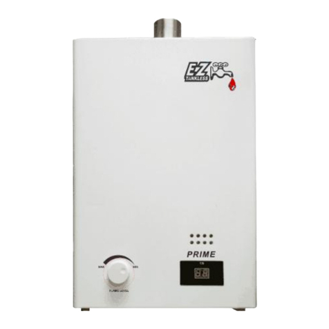
EZ TANKLESS EZ OUTDOOR User manual

EZ OUTDOOR
TANKLESS WATER HEATER
EZtankless.com
SPECIFICATIONS
Model EZ OUTDOOR
Rated heat input (kW) 3
Hot water supply (for 60°F tem. rise) (GPM) 5.5
External dimensions 3.7" x 15.5" x 5.5"
Water pressure operational range (PSI) 35 ~ 100 PSI
Thermal efficiency rating 88%
Gas type & rated gas pressure Pa (PSI) (WCI) LPG 800 (0.46) (11”)/NG 000 (0. 9) (8”)
Voltage (V) AC110V 60HZ
Shipping carton dimensions 9.5” x 17.7” x 8.9”
Shipping weight G.W. /N.W. kg (U.S. Pounds) 15.5/14 (34/31 lbs.)
Connections:
GAS = USA ¾ inch pipe thread
Water = USA ½ inch pipe thread (3/4 inch adapters included - Qty. )

1
SPECIAL FEATURES
(1) Special Inner Structure Design and Stainless Steel Cover.
( ) Large Water Flow and Constant temperature Water Supply.
(3) Outdoor Installation Style to Save Indoor Space. (For use only in warm “no-freeze” climates)
(4) Waterproof Wiring and Controls for Longer Operation.
(5) Featuring Six Hi-Efficiency Technologies.
(6) Advanced Intelligence Wind-Air Pressure and Downdraft Detection.
(7) Very Low Water Pressure start-up.
(8) AI Intelligent Memory function.
(9) Self adjusting fan motor.
(10) Twelve safety precaution-protection systems.
* All specifications are subject to change without notice
Please read this man al before installation and operation and keep it for f t re reference.
CONTENTS
•Precautions ------------------------------------------------------------------------
•Design and performance characteristics -------------------------------------- 3
•Installation requirements ------------------------------------------------------- 3
•Initial start-up -------------------------------------------------------------------- 5
•Safety precautions --------------------------------------------------------------- 6
•Maintenance ---------------------------------------------------------------------- 7
•Trouble Shooting codes --------------------------------------------------------- 7
•Trouble shooting ----------------------------------------------------------------- 8
•Temperature conversion chart ------------------------------------------------- 9

2
GENERAL PRECAUTIONS
This gas water heater can produce carbon monoxide gas and displace-consume a great deal of room
air. Inhalation of carbon monoxide can lead to serious injury or death. Carbon monoxide is harmful
or fatal for all animals, humans and most life forms.
This machine is designed for use outdoors in a well ventilated area.
NEVER install this nit inside an inhabited b ilding or enclosed area.
This machine must be installed by a professional in a safe way as per the precautions and
instructions provided. As well as conforming to all local safety codes. We hold no liability expressed
or implied for damages of any kind, injury, or death caused directly or indirectly by errors in
installation, improper or unsafe use, or installations done by those persons not qualified to do so.
DESIGN AND PERFORMANCE CHARACTERISTICS
This product is a gas fired tankless water heater.
The fuel is gas (Natural Gas AKA NG or LPG AKA LP Liquid petroleum)
This product will supply a continuous supply of hot water within the parameters of its specifications.
It is suitable for bathing, showering, hand washing, clothes washing, and other washing duties.
Drinking note: As with ALL water heaters of any design, it is not advisable to drink water directly
from this device unless the water has been heated to a high enough temperature known to kill all
harmful bacteria.
This unit is designed for outdoor mounting and installation only. It is designed to be rain-proof. It is
not designed to be submerged in floodwater. Location for mounting must be above the flood plain.
This unit takes in outdoor air and it releases its exhaust into the outdoors. For this reason it does not
use an exhaust pipe.
Users need only to operate this heater with the supplied remote control being certain to keep in
mind the safe temperature to prevent scalding. Use only the supplied wire for the remote control as
it has a special resistance construction for this purpose.
NOTE: In case of a power failure, the heater will shut down in a safe manner. It will restart upon the
return of the electrical supply.
There is a self-diagnostic system that checks the state of each safety device, the fan, gas valve, and
will shut-off if any malfunctions are detected. It will then display the malfunction code which
corresponds with the list of troubleshooting solutions supplied in this manual.

3
The microprocessor advanced intelligence system analyzes and automatically adjusts the parameters
of the internal systems according to ambient air temperature, water pressure, gas flow, and
incoming water temperature. By using a high-precision and reliable water flow sensor, the user-
selected pre-set gives consistent water temperature for worry-free operation.
The gas control valve is controlled by a micro-processor which instantly calculates and controls the
gas supply which saves on consumption and works in unison with the speed of the fan motor for
proper combustion mixture and maximum efficiency. With this forced-air system the effects and
efficiencies of the heat exchanger is much greater than the models that are non-fan forced.
This model features a low water pressure start-up for use in areas where there is lower pressure.
Memory system restarts the heater in the previously selected settings.
Multi-function self diagnosis featuring flame-out protection, exhaust pressure self diagnosis,
overheating protection, combustion mixture, and anti-freeze protection.
INSTALLATION REQUIREMENTS
Before installation, contact your local gas company and/or a qualified installer for a proper
installation. Installation by unqualified personnel is forbidden by most local codes and is dangerous.
*We hold no liability expressed or implied for damages of any kind, injury, or death caused directly or
indirectly by errors in installation, improper or unsafe use, or installations done by those persons not
qualified to do so.
•Mount the heater in a location that is outdoors in a well ventilated area such as an open
yard.
•To avoid exhaust gasses from entering into the dwelling, the heater must be located a safe
distance from any window or door opening. (Minimum of five feet in every direction.)
•This water heater CANNOT BE INSTALLED INDOORS for any reason.
•Always select a mounting area that is well clear of humans or animals to protect life and
health. Keep in mind that even though this device is very quiet, it should be considered that
any sound it produces will not disturb others.
•No flammables or other devices should be near this heater. DO NOT ATTEMPT to install a
vent hood or exhaust fan above this heater. IT IS NOT FOR INDOOR USE! Do not modify this
heater in any way!
•Always plug into only a three prong outlet that is properly wired and grounded. NEVER USE
an extension cord to connect the power supply. Ground-fault interrupted waterproof
exterior types are best.
•Do not tilt the heater in any way. It must be installed upright at all times.
•The heater must be securely mounted with screws.
•Gas connections must be up to local code as per type of gas and applications.

4
•There should be a gas cut-off valve near the heater. In this way, the gas supply can be
turned-off for maintenance or in case of emergency.
•All gas lines must be checked for leakage at the connections.
•Water inlet and outlets should have in-line shut-off valves to isolate the zone in case the
heater must be removed for repair or to supply access for flushing and cleaning of the unit.
•Special tankless heater service-valve sets are available and are the best way to install the
water to the unit.
•It is best to filter the incoming water as this will keep the interior of the heater clean.
•The remote controller must be installed indoors and should be mounted at a convenient
location.
•Do not plug-in electrical supply until the installation is complete. (including the remote
control)
REMOTE CONTROL INSTALLATION INSTRUCTIONS
•Install the control panel inside the building. Mount it in an easy to use location. The
supplied (30 foot long) control cable has a metal plug-in which attaches to the bottom of
the heater. The location is clearly marked. (Remove the small plastic receptacle protection
cover to install the plug-in)
NOTE: The control cable has a red and a blue wire and the controller has two black wires
that connect to the control cable. It does not matter which wire connects to the controller.
(The red wire connects to either one of the controller’s black wires, the blue wire connects
to the opposite controller black wire, they are not polarity specific) Attention: The
controller must be connected for the heater to operate correctly. Failure to use the
controller may damage the heater, will void all warranty and poses the potential of
scalding!
•To avoid interference, the control cable should not be located within a conduit with other
electrical wires.
•The controller code is pre-set at the factory at 50c ( 1 F ).

5
INITIAL START-UP
•Be certain the type of gas matches the model of the heater. (LP or NG)
•Open the water inlet valve.
•Open a hot water faucet.
•Insert the electrical power supply plug into the socket.
•Open the gas valve completely.
•Press the on-off button on the controller to turn on the display.
•Set the desired water temperature by pressing the up and down temperature keys.
•After a few seconds the heater will begin to operate and deliver the desired pre-set
temperature of hot water.
•The icon which indicates combustion will illuminate when the heater is making hot water.
•If there is an alarm or fault code, turn the heater off with the off-on button and proceed to
the trouble shooting section of this manual or contact us for further assistance.
•When the hot water faucet is turned-off the heater will shut down automatically. It is not
necessary to turn off the off-on button. When leaving for long periods such as vacation it is
best to turn off the button on the controller. This way, if a pipe were to burst, the heater
would not turn on.
•NOTES: The water temperature may be slightly lower than the setting due to length of
pipes and air temperature in the area in which the pipes are located.
•When the GPM of water flowing through the heater is above its GPM maximum rating, the
heater will not be able to produce a sufficient supply. The water temperature will drop
until the GPM comes to within the range of the heater’s capability.
•If the heater’s gas supply is interrupted, it may take several ignition attempts for the air to
be purged from the gas line before the heater operates correctly. Please be patient when
this happens. Eventually the lines will purge and the unit will ignite.
•Always use the hands to test the water temperature before immersing the body into the
flow to avoid scalding.
•If a faucet is opened while the heater is unplugged, the heater will not turn on until the
cord is plugged into the outlet, and then a faucet is closed and opened again. This is a self-
protection mode.

6
SAFETY AND GENERAL COMMON SENSE PRECAUTIONS
•IT IS EXPRESSLY FORBIDDEN TO USE THIS HEATER INDOORS! There is no exhaust pipe!
•Check the vent frequently for nests and debris. Especially after a long period without use.
•Prevent scalding. Keep the heater set at a safe temperature.
•Mount the heater in a location away from small children and animals. The exhaust opening
can be of high temperature during and immediately after use. Do not touch this area.
•Please be aware of flammable materials in the vicinity of the heater. Such as pine needles,
dry grasses, rags, paper etc… Prevent fires by being aware of these things.
•Mount the heater in a location as to not conduct lightning. Be aware that a lightning strike
can ruin this device.
•Be sure to include a notation of this device with your insurance company if required.
•It should be mounted in a location so as to prevent it from being stolen. In some areas,
users build a metal wire frame cage in which to enclose the heater to prevent theft.
•Always check for gas leakage. A professional should check all connections after installation
and at times in the future. Be sure to mount the gas lines in a way that they will not be
disturbed by children playing or being inquisitive, lawn mowing, gardening, or general
home activities.
•Never install this heater in a place that can freeze. In case of an unusual freeze prediction,
it is best to turn the heater off, and completely drain it before the freezing occurrence. If
this heater is used for a seasonal application such as a lake cabin, it should be completely
drained, disconnected and placed indoors for safe keeping. This is the type of thing that
can disappear from the lake home during long periods without use and will last longer if
protected from harsh weather when not in use for these long periods.
•To prevent freezing, shut off the power button. Shut off the water supply to the heater.
Open and drain all the water from both the hot and cold sides of the heater. Blow air
through the water pipes of the heater to be sure it has been completely drained.
•For LP – LPG users, an unstable flame may be caused by a malfunction of the gas regulator
valve which is typically located at the gas storage tank itself. Immediately stop using the
heater and contact a professional technician for assistance.
•For NG (Natural Gas) users, if the becomes unstable this may be caused by instable gas
pressure. Immediately stop using the heater and contact a professional technician as this
may be a dangerous situation and can damage the heater.
•Never place flammables on the heater. It is not to be used for drying objects or clothing.
•For LPG users, never tilt or invert the tank for any reason. Always use a national standard
type of regulator valve.
•LPG users must be aware that when the tank runs low on gas, there can be a carbonizing
situation which can cause deposits in the combustion chamber. In this case, the flame will
turn from blue to yellow, smoke will usually be emitted from the exhaust and increased
carbon monoxide will be produced. In this case, shut down the heater and refill the tank.
•The heater must be installed vertically.
•In case of an abnormal burn. E.g. backfire, flame-out, yellow flame, black smoke, unusual
smell, noise, or other abnormal occurrences, shut down the heater and contact a service
professional.

7
•The ELECTRICAL plug-in should be attached to a high quality outdoor waterproof type
outlet. Installed in a safe place so as not to short circuit and should be properly grounded
and installed by a qualified professional electrician. Use wire in conformity of all local,
state, and federal codes. It is best to use a ground-fault protected plug.
MAINTENANCE
•Check gas and water lines for leaks often.
• Clean the inlet water line filter.
•If there has been a smoking condition due to a poor burn, the unit should be cleaned inside
by a professional technician.
•Keep the cover and heater clean.
•During high humidity and lower temperatures it is normal for some fogging to occur to the
exhaust.
•To prevent the build-up of scale inside the heater, it should be flushed at least once per
year. The water inlet should be filtered to lower the hardness and impurities. Soft water
will add to the life of the heater.

8
TROUBLE CODES
Fa lt code Symptoms
E0
The water inlet thermostat has failed
E1
No flame or an unexpected flame
-
out
E3
Flue is clogged o
r very high wind pressure or no wind pressure
E4
Fan or fan circuit fault
E5
Over high temperature protection. (85 c
-
185 F)
E6
Fault in temperature sensor of the outlet water side
E7
Gas
-
type switch fault
PROBLEM
POSSIBLE SOLUTION
No i
gnition when water is turned on
Gas valve not open
–
air in gas line
–
unsuitable gas pressure – No inlet water
supply –frozen –inadequate water supply –
too high wind speed or pressure – water
control unit failure – incorrect ignition
electrode distance – no electrical power to
unit – short circuit
The flame goes out
Gas valve partially closed
–
low gas pressure
–
inadequate water supply – insufficient air
supply – too high wind speed or pressure –
heat exchanger clogged – water control unit
failure – no electrical power to unit – short
circuit
Abnormal noise during ignition
Too high of gas pressure
–
too high wind
speed or pressure – incorrect ignition
electrode distance
Yellow flame
Not enough gas supply or too low gas
pressure
Abnormal smell
Inadequa
te air supply
–
burner clogged
–
heat
exchanger clogged
Loud noise when ignited
Too high of gas pressure
–
burner clogged
Low water temperature when set to
maximum heat position
Gas valve partially closed
–
low gas pressure
–
error in setting controls – water control unit
failure
High water temperature when set to
minimum heat position
Error in setting controls
–
water control unit
failure
When set in low temperature position the
flame goes out
Inadequate water supply
Unit continues to burn after wat
er faucet is
turned-off
Water control unit failure

9
CELSIUS TO FAHRENHEIT CONVERSION CHART
www.eztankless.com
* All specifications are subject to change without notice
Table of contents
Other EZ TANKLESS Water Heater manuals
Popular Water Heater manuals by other brands

State Water Heaters
State Water Heaters SBD71120 Service handbook

Bulldog Security
Bulldog Security 40861-EU/UK instructions

CTC Union
CTC Union CTC Accumulator Tank 1. 300/20 Installation and maintenance manual

Webasto
Webasto Thermo Top E installation instructions

ATI di Mariani
ATI di Mariani BB02005X instruction manual

Marey
Marey GA22ONG use and care manual