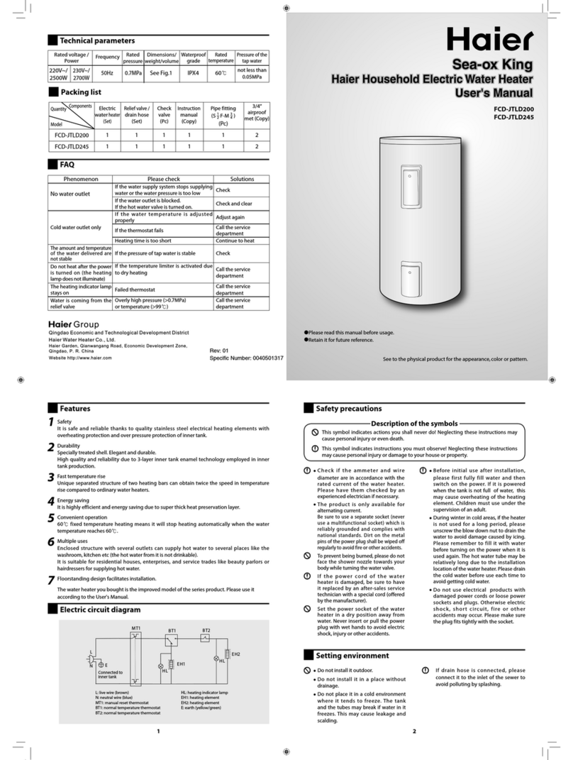
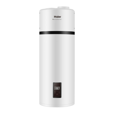
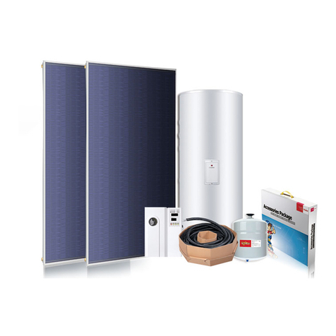
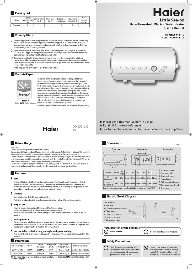
manuals.online logo
Brands
  1. Home
  2. •
  3. Brands
  4. •
  5. Haier
  6. •
  7. Water Heater
  8. •
  9. Haier HP80M5 Specification sheet

Haier HP80M5 Specification sheet

Heat pump Water Heater
●
Operation and Installation Manual
Model
HP80M5
HP110M5
Please read this manual carefully prior to
●
your use of this water heater.
The appearance of the water heater given
in this manual is for reference only.
English
ELECTRICITE
Contents
1. Safety instructions ............................................................................................................... 3
2. Instructions on transportation and storage
●
........................................................................ 6
3. Functionings & principles ..................................................................................................... 6
4. Technical parameters ........................................................................................................... 7
5. Description of parts and components ................................................................................ 8
6. Installation introduction ..................................................................................................... 11
7. Operation and functions ..................................................................................................... 24
8.Checking and maintenance.................................................................................................. 27
9.Faults and protection
●
.......................................................................................................... 28
10.Product Fiche ..................................................................................................................... 29
Dear users of Haier,
Thank you for choosing Haier products.
Please read this manual carefully and follow the operation and safety instruction to ensure
best installation and utilization of the product.
Product safety statement:
1.This appliance can be used by persons with reduced
physical, sensory or mental capabilities or lack of experience
●and knowledge if they have been given supervision or
instruction concerning use of the appliance in a safe way and
understand the hazards involved.
2. Children shall be closely supervised to make sure they stay
●away from this product.
3.The method of installing safety valve please refer to Page 16.
4.The water may drip from the discharge pipe of the pressure
relief device and this pipe must be left open to the
atmosphere.
5.The water heater is to be drained according to the
Safety instructions (to be followed at any time)
Failure to respect these instructions may lead to serious malfunctions of the
●
device and to risks for the user
Instructions with this warning mark shall be strictly followed during operation.
They relate to product and body safety of users.
Information provided with this banning mark relates to activities that are
●
risk personal danger.
The water heater shall be
installed in strict accordance
with local wiring regulations,
and equipped with power
supply with a ground line.
●
ground connection.
It is recommended that the
●
water heater shall be installed
inside.
The water heater shall not be
installed at places where
water drainage is unavailable
or impossible.
While bathing, children must
be under guidance of an adult
person.
●
This water storage tank must
be equipped with a safety
valve. Its installation position
shall not be changed. To
guarantee safe operation, it
shall not be blocked at any
time.
Ground line and zero line of the
power supply shall not be
connected together. The
ground line shall not be
connected to pipeline
conveying gas or water,
lightning arresters or
telephone lines.
Interpretation of marks and symbols
English
The outlet water temperature
●
of a water heater is typically
higher than the temperature
indicated on the display. Hot
water shall not be pointed at
●
the human body immediately
after opening the hot water
valve to avoid injury caused by
hot water.
Hands or other items shall not
●
be put into the air grille to
avoid injury or damage to the
water heater.
Means for disconnection from
the main supply having a
contact separation in all poles
that provide full
disconnection under
overvoltage category III
conditions must be
wiring in accordance with the
wiring rules.
If the power cord is damaged,
it shall be replaced by
avoid hazards.
Install the water heater in
strict accordance with the
installation instruction
Maintenance shall be carried
out according to the
page 27.
Safety instructions (to be followed at any time)
The water heater is intended to be permanently
connected to the water mains and not connected by a
●
Do not install the water heater in the position where
●
exposed to gas, vapours or dust.
Rotate the safety valve handle
once a month. The valve
works well if there is water
for blocking and replace the
●
safety valve if necessary.
Chemical name of the gas: R134a/ 0,45Kg
●Fluorinated greenhouse gases are contained in
hermetically sealed equipment.
Global Warming Potential(GWP) : 1430
Water heaters shall be
equipped with a dedicated
power line and residual
current circuit breakers. The
action current shall not
exceed 30 mA;
Safety instructions (to be followed at any time)
The water drain pipe shall be in connection with the
atmosphere, it shall not be blocked; the water drain pipe
connected to a safety valve shall be installed in a frostless
environment with an continuous downwards inclination.
5
●
English
In accordance with safety rules, a safety valve(8bar,G1/2F)
must be installed on the tank. For France, we recommend
marking. The rated pressure of the safety valve shall not
exceed 0.8MPa.
If needed, please refer to the wiring diagram on page 23.
The method of connection about the appliance to the
electrical supply refer to page 21.
5
Instructions on transportation and storage
Functionings & principles
●
1. During transportation or storage, the heat pump water heater shall be packed in the
undamaged package to avoid damage to appearance and performance of the product;
2. During transportation or storage, the heat pump water heater shall be in the upright
position;
3. Under special conditions, this product may be laid down for a short time/distance as
per indication on the side of the package case. The heat pump water heater, after being
laid down for a certain time, shall be kept at upright position for more than 4 hours before
starting up.
The machine shall be kept in the upright position at any time for the best
performance !
into the compressor. As the pressure of the refrigerant increases, so does its
●
temperature. The heated refrigerant runs through a condenser coil within the storage
●
tank, transferring heat to the water stored there. As the refrigerant delivers its heat to the
●
water, it cools and condenses, and then passes through an expansion valve where the
pressure is reduced and the cycle starts over.
6
7
Technical parameters
Model HP80M5 HP110M5
Tank volume 82L 105L
Rated voltage/ frequency 220V~240V/50Hz 220V~240V/50Hz
Tank rated pressure 0.8MPa 0.8MPa
Corrosion protection Magnesium rod Magnesium rod
Water proof grade IPX4 IPX4
Type of ex
●
traction Ambient / Exterior Ambient / Exterior
COP@7 / EN16147 2.74 2.73
COP@14 / EN16
●
147 3.04 3.02
Tapping cycle M M
Power input by electric backup 1200W 1200W
Rated power input by heat pump 240W 240W
Maximum power input by heat pump 350W 350W
Maximum
●
power input 1550W 1550W
Standby power input/ Pes 21W 21W
Max volume of usa
●
ble hot water at 40
setting at 55 103L 132L
Heating up time (7 ) 5h07 6h38
Heating up time (14 ) 4h35 5h56
Default temperature setting 54 54
Temperature setting range- with heater 35 -75 35 -75
Maximum length of air duct
160mm
Max working pressure of refrigerant 0.8/2.8MPa 0.8/2.8MPa
Refrigerant type / weight R134a/0.45kg R134a/0.45kg
Sound power level 50dB
(A)
50dB
(A)
Ambient temperature for use of product -7~45 -7~45
Operating temperature of heat pump -7~45 -7~45
Water inlet and outlet connection G1/2"M G1/2"M
Safety valve connection G1/2"M G1/2"M
Drain & Water intl
●
et connection G1/2"M G1/2"M
Product Dimensions
492*537*1170mm 492*537*1320 mm
Packing dimension without pallet
587*587*1247mm 587*587*1397 mm
Net/Gross weight 52/59kg 65/73kg
* The COP and noise level data was tested in Haier lab.
Tank
Performances
Dimension and connections
English
Diameter of air duct connection
5m 5m
160mm
Description of parts and components
Accessories
●
Part
name
Heat pump
water heater Safety
val
●
ve
Drainage pipe for
condensate water
Support
plate
Quantity 1111
Inlet for cold
water/drain
outlet
Hot water
outlet
Heat pump structure
8
Condensate outlet
Air outlet
Air inlet
Instruction
manual
1
HW
SET
ACT
START
STOP
1
2
HP HC
TIMER
MODE
HP
SET
A
C
T
T
OP
SET
BOOST
Description of parts and components
Exploded view
9
2
●
1
4
3
6
5
17
12
1
Electric heater
2
Electric cover
3
Cover for display
4
Display panel
5
Front cover
6
Control box
7Compressor
8
Air grille
9
ront
10
F
●
an
11
Four way valve
12
Top cover
13
14
15
●
Description
16
15
14
8
7
13
11
10
18
9
Electronic expansion
valve
Evaporator
16
Motor
17 Back cover
18 Support plate
English
Installation introduction
Installation precaution
Keep an adequate distance between the working heat pump and the resting
●
room.
and the condensate water can be drained freely.
functions.
running: from 2
10
English
●
Installation introduction
Installation dimensions
M
●
odel
HP80M5
HP110M5
AB
140
140
492
492
C
1170
D
538
5381320
E
Unit:mm
11
A
BD
E
C
F
159
159
362
362
F
Installation introduction
Installation dimensions
12
Installation angle refer t
●
o the following
diagrams
300mm
830mm
90°< <91
●
°
159mm
Note: these two expansion bolts can support
200kg weight at least .
After the installation is completed, it is necessary
to use a level ruler to check whether the support
is maintained in a horizontal state.
English
●
Installation introduction
Air connection
160mm
●
duct.
the fan.
impaired.
The sum of the maximum length of the air duct is 5m
●
13
click
Garage or laundry room (without ducts):
●
Laundry room (with one duct):
●
Habitable room or outside air (with two ducts):
●
too
●
low,connection to the outside air may lead to
overconsumption of electricity.
14
Installation introduction
Advised positions
Installation introduction
Installation caution
When making the
●
connections, you should respect the standards and
local directives.
- Before making the connection, rinse the water inlet pipes, in order not to
introduce metal or other particles into the tank.
- Select copper pipes for pipeline connection.
- The inlet water pressure is be
●
tween 0.1~0.5MPa. If lower than 0.1 MPa, a
booster pump shall be added at the water inlet; if higher than 0.5 MPa, a
pressure relief valve shall be added at the water inlet.
- The inlet water temperature is suggested between 10-30°C.
- Outdoor water pipeline and valves should be proper insulated.
- In accordance with safety rules, a safety valve(8bar,G1/2F) must be
installed on the tank.For France, we recommend hydraulic safet tted
with a membrane with the NF marking.
Integrate the safety valve in the cold water circuit.Install the safety valve close
to the tank in a place which is easy to access.
No isolating devices should be located between the safety valve or unit and the
tank.
The rated pressure of the safety valve shall not exceed 0.8MPa.
- Never block the outlet of the safety valve or its drain line for any reason.
- The diameter of the safe
●
ty unit and its connection must be atleast equal to the
diameter of the domestic
●
cold water inlet.
- If the mains pressure exceeds 80% of safety valve, a pressure reducer must be
installed upstream of the appliance.
If the air inlet and outlet of the product are not installed with air ducts,
●
the air inlet and outlet of the product shall be protected to prevent water
15
English
- NOTE: Don’t install and use the product outdoors.
Installation introduction
Pipeline installation diagram
Installation A
Installation B(for France only)
local market;
Thermostatic
valve
Water outlet of
safety valve
Check valve
Outlet of
condensate
water
Hot water
outlet
Cold water inlet
Water outlet
Stop
valve
Pressure
relief valve
Check
valve
230V
50Hz
Con
●
nected to water inlet
of the water tank
Check
valve Stop
●
valve
Safety valve
Sewage drainage
outlet
Thermostatic
valve
W
●
ater outlet of
safe
●
ty valve
Check
valve
Pressure relief valve Combination valve
Outlet of
condensate
water
Hot water
outlet
Cold water inlet
Water outlet
230V
50Hz
2CM
16
Drain valve
English
●
Installation introduction
Electrical connections precautions
- Water heaters shall be equipped with a dedicated power line and residual
current circuit breakers. The action current shall not exceed 30 mA;
- The ground line and the null line of the power supply shall be separated
entirely. Connecting the null line to the ground line is not allowed.
- Parameter of the power line: 3×1.5mm² or more.
- If a po rofessionals to
avoid risks.
- In the case of places and walls where water may be splashed to, installation
height of a power socket shall not be less than 1.8 m, and it shall be ensured
that water would n
●
ot be splashed on these places. The socket shall be
installed out of children’s reach.
- The phase line, zero line and ground line inside a power socket used in your
home shall be wired correctly without any wrong positioning or false
connection, and internal short circuit shall be avoided. Wrong wiring may
s.
WARNING
rofessionals may carry out electrical connections,
always with the power o .
- The earthing shall comply with local standards.
17
Connection to a PV system
17
123kwh 1
0
F2 = 16A
DC
●
AC
Control cable for automatic
connection/disconnection
of the power supply
●
(2*0.75 mm², black cable)
Power cable
(3*1.5 mm²)
F1 = 2A
Available power
(mini threshold = 700 w)
Inverter State Grid
Photovoltaic panels
Installation introduction
18
Power cable (3*1.5mm
●
2 )
(2*0.75mm2 ,Black wire)
16A
Auto
1
0
123kwh 1
0
English
19
Wiring diagram
Commissioning
●
Installers shall use checking list for trial operation of water heaters as per the user manual
●
and make in .
●
Materials for hot/cold water pipes conform to requirements of
●
ole water pipeline. There
ng out after pressure is
Installation introduction
R
SC
K3
CT1
Blue
MAIN BOARD
FAN
K4
K5
L
( )
(
N
)
CN9
CN19
CN16
N
Leakage
protection coil
GND
Compressor
capacitor
White
Compressor
Blue Blue
White
Black
Brown
Blue
Four-way valve
White
Discharge temperature
sensor
Defrost temperature
sensor
Ambient temperature
sensor
Suction temperature
sensor
Water tank temperature
sensor
Power cord
CN1
EXV
CN5 CN2
CN11
Terminal block
Current
transformer
CN24
CN27
CN28
20
Operation and functions
Display
Functions & Protections
●
Electrical leakage protection
The control system of this machine features an electricity leakage protection function.
●
Automatic defrosting function
●
Overload protection
●
The heat pump starts heating to avoid freezing of the water tank if the temperature in
the water tank is too low.
●
A.
C.
D.
E.
F.
When restarting the machine immediately after shutdown, the system goes into the
protection mode and starts after approximately 3 minutes, which is considered to be
normal.
The defrosting mode is automatically activated if the outdoor temperature is too low
and after the compressor already runs continuously for a certain period.
The working load of the compressor will be heavy if temperature is high in summer. In
order to meet hot water requirements of users and to lengthen service life of the
compressor, this product automatically adjusts the fan speed to ensure reliable
operation of the compressor.
When starting the machine after electricity input, the system will start after
approximately 3 minutes ,which is considered to be normal.
B.

This manual suits for next models

1

Other Haier Water Heater manuals

Haier ES25V-M1 User manual

Haier

Haier ES25V-M1 User manual

Haier ES10V-Q1 User manual

Haier

Haier ES10V-Q1 User manual
Haier ES6VQ1 (R) User manual

Haier

Haier ES6VQ1 (R) User manual

Haier TP180REL Specification sheet

Haier

Haier TP180REL Specification sheet

Haier FCD-JTHA30-III User manual

Haier

Haier FCD-JTHA30-III User manual

Haier ES100V-U1

Haier

Haier ES100V-U1

Haier Little Sea-ox FCD-30 User manual

Haier

Haier Little Sea-ox FCD-30 User manual

Haier SILVER SEA-OX FCD-JTHMG100- E User manual

Haier

Haier SILVER SEA-OX FCD-JTHMG100- E User manual

Haier FCD-JTHC80A-III (E), FCD-JTHC100A-III (E) User manual

Haier

Haier FCD-JTHC80A-III (E), FCD-JTHC100A-III (E) User manual

Haier FCD-6.6 User manual

Haier

Haier FCD-6.6 User manual
Haier FCD User manual

Haier

Haier FCD User manual

Haier ES35HH1 (R)

Haier

Haier ES35HH1 (R)

Haier S110ENF User manual

Haier

Haier S110ENF User manual

Haier FCD-JTHA50-III User manual

Haier

Haier FCD-JTHA50-III User manual

Haier ES100V-R1 User manual

Haier

Haier ES100V-R1 User manual

Haier HP200S1 Specification sheet

Haier

Haier HP200S1 Specification sheet

Haier Little Sea-ox FCD-JTHC40-III (E) User manual

Haier

Haier Little Sea-ox FCD-JTHC40-III (E) User manual

Haier HP150M5 Specification sheet

Haier

Haier HP150M5 Specification sheet

Haier FCD-JTLD200 User manual

Haier

Haier FCD-JTLD200 User manual

Haier GV100RNF User manual

Haier

Haier GV100RNF User manual

Haier FCD-JTLD100 User manual

Haier

Haier FCD-JTLD100 User manual

Haier ES100V-R1(H) User manual

Haier

Haier ES100V-R1(H) User manual

Haier Little Sea-ox FCD-JTSA50-III User manual

Haier

Haier Little Sea-ox FCD-JTSA50-III User manual

Haier FCD-8 User manual

Haier

Haier FCD-8 User manual

Popular Water Heater manuals by other brands

Zip Hydroboil Plus 3 Litre White HP003 Installation and operating instructions

Zip

Zip Hydroboil Plus 3 Litre White HP003 Installation and operating instructions

Bradford White UCG100H270 Installation and operation manual

Bradford White

Bradford White UCG100H270 Installation and operation manual

Bosch BC2680RA installation manual

Bosch

Bosch BC2680RA installation manual

Facilities Resource Group TTS-TWST2 installation manual

Facilities Resource Group

Facilities Resource Group TTS-TWST2 installation manual

Bosch Tronic 1500 TO Series Installation and operating instructions

Bosch

Bosch Tronic 1500 TO Series Installation and operating instructions

HTP Versa Hydro PHE130-55 Installation start-up maintenance parts

HTP

HTP Versa Hydro PHE130-55 Installation start-up maintenance parts

Webasto Thermo Pro 90 installation instructions

Webasto

Webasto Thermo Pro 90 installation instructions

STIEBEL ELTRON DHB-E 18 SLi 25 A electronic Operating and installation instructions

STIEBEL ELTRON

STIEBEL ELTRON DHB-E 18 SLi 25 A electronic Operating and installation instructions

GE GEH80DEEJS Owner's Manual & Installation Instructions

GE

GE GEH80DEEJS Owner's Manual & Installation Instructions

GE GeoSpring GEH5ODEEJS Owner's Manual & Installation Instructions

GE

GE GeoSpring GEH5ODEEJS Owner's Manual & Installation Instructions

ESP Ecocent 250T Installation and operation manual

ESP

ESP Ecocent 250T Installation and operation manual

Noritz NRC1111-OD owner's guide

Noritz

Noritz NRC1111-OD owner's guide

OSO HOTWATER Maxi Accu Series user manual

OSO HOTWATER

OSO HOTWATER Maxi Accu Series user manual

Ferroli DIVAtop MICRO C Instructions for use, installation and maintenance

Ferroli

Ferroli DIVAtop MICRO C Instructions for use, installation and maintenance

Kospel MAXIMUS EPP-36 manual

Kospel

Kospel MAXIMUS EPP-36 manual

Bosch Tronic ES 030 Series User and installation manual

Bosch

Bosch Tronic ES 030 Series User and installation manual

Slant/Fin VICTORY II VHS Series Installation and operating instructions

Slant/Fin

Slant/Fin VICTORY II VHS Series Installation and operating instructions

Ariston ABS VLS EVO POWER 30 Instructions for installation, use, maintenance

Ariston

Ariston ABS VLS EVO POWER 30 Instructions for installation, use, maintenance

manuals.online logo
manuals.online logoBrands
  • About & Mission
  • Contact us
  • Privacy Policy
  • Terms and Conditions

Copyright 2025 Manuals.Online. All Rights Reserved.