EZAutomation EZ Touch EZ7 Series User manual

Doc Ver 1.0,
08/2019
EZAutomation.net
1-877-774-EASY (3279)
EZ Series HMI Quick Start Guide

1 / 31
Table of contents
Contents
Introduction......................................................................................................................................................3
1.1 System Diagram........................................................................................................................................3
Part Numbers....................................................................................................................................................4
Specifications....................................................................................................................................................5
Installation ........................................................................................................................................................6
4.1 Guidelines .................................................................................................................................................6
4.2 Dimensional Drawings ............................................................................................................................10
4.2.1 Overall Dimensions.........................................................................................................................10
4.2.2 T7C (7” Display) Mounting dimensions ..........................................................................................11
4.2.3 T8C (8” Display) Mounting dimensions ..........................................................................................11
4.2.4 T10C (10” Display) Mounting dimensions ......................................................................................12
4.2.5 T12C (12” Display) Mounting dimensions ......................................................................................12
4.3 Mounting Instructions ............................................................................................................................13
Ports and Wiring .............................................................................................................................................16
Quickstart .......................................................................................................................................................17
6.1 EZTouch editor........................................................................................................................................17
6.2 Create a Project ......................................................................................................................................18
6.3 Transfer Project ......................................................................................................................................21
6.4 Set IP Address .........................................................................................................................................22
6.4.1 Using EZTouch Editor Serially Connected to EZ7:...........................................................................22
6.4.2 Using IP Config Utility: ....................................................................................................................24
6.5 Setting Date/Time...................................................................................................................................25
Maintenance and Troubleshooting ................................................................................................................26
7.1 General ...................................................................................................................................................26
7.2 Display Verification Tests........................................................................................................................27
7.3 Update Firmware....................................................................................................................................28
7.4 Troubleshooting......................................................................................................................................30
Still Need Help?...............................................................................................................................................31

2 / 31
Warnings
Programmable control devices such as the EZ7 Series HMI are not fail-safe devices and as such must
not be used for stand-alone protection in any application. Unless proper safeguards are used,
unwanted start-ups could result in equipment damage or personal injury. The operator must be
made aware of this hazard and appropriate precautions must be taken. In addition, consideration
must be given to the use of an emergency stop function that is independent of the EZ7 Series HMI.
The diagrams and examples in this user manual are included for illustrative purposes only. The
manufacturer cannot assume responsibility or liability for actual use based on the diagrams and
examples.
Trademarks
This publication may contain references to products produced and/or offered by other companies.
The product and company names may be trademarked and are the sole property of their respective
owners. AVG Automation disclaims any proprietary interest in the marks and names of others.
Manual part number EZ7-TC-M
© Copyright 2019, EZAutomation
All Rights Reserved
No part of this document shall be copied, reproduced, or transmitted in any way without the prior
written consent of AVG Automation. AVG Automation retains the exclusive rights to all information
included in this document.
Designed, Built and Marketed by AVG
4140 Utica Ridge Rd. · Bettendorf, IA 52722-1327
Phone: 1-877-774-EASY · Fax: 1-877-775-EASY · flash.ezautomation.net
EU Information
The EZ7 Series HMI is manufactured in compliance with European Union (EU) Directives and carries
the CE mark. They been tested under CE Test Standard #EN55011, and is submitted for UL
Certification. Products with CE marks perform their required functions safely and adhere to relevant
standards as specified by EU directives provided they are used according to their intended purpose
and that the instructions in this manual are adhered to. The protection provided by the equipment
may be impaired if this equipment is not used in accordance with this manual. Only replacement parts
supplied by AVG Automation or its agents should be used.
Technical Support
Consult Panel Editor Programming Software Help. You may also find answers to your questions in the
operator interface section of our website @ flash.ezautomation.net. If you still need assistance,
please call our technical support at 1-877-774-EASY or FAX us at 1-877-775-EASY.
SELV Circuits
All electrical circuits connected to the communications port receptacle are rated as Safety Extra Low Voltage
(SELV).

3 / 31
INTRODUCTION
Thank You for your interest in AVG Automation’s latest unique offering, the EZ7 Series HMI.
EZ7 HMI is two piece products: Front part consisting of display (and touch screen) housed in metal,
and a back part that has HMI processor. Front part is installed on the front of the control cabinet,
while the back part is installed on the back of the control cabinet door. The two are connected using a
cable.
This construction has following benefits:
•No large cutouts for the HMI, only drill holes for the studs, and a hold for cable
•Easily replace worn-out touch screens instead of changing whole unit
•If required, upgrade to larger display sizes without need to change the back.
•Use the same EZTouch editor that is used for other EZTouch families of HMI
•Support for a variety of PLC Protocols including DH+ and Remote I/O
1.1 SYSTEM DIAGRAM
Connection Cable
Serial or Ethernet or USB Connection
Serial or Ethernet Connection
PC running
EZTouch Editor
EZ7 HMI
PLC or
Controller

4 / 31
PART NUMBERS
EZ7 is available in 7, 8, 12, and 15 inch display sizes:
EZ7DT-T7C-E EZ7 7” Inch HMI
EZ7DT-T8C-E EZ7 8” Inch HMI
EZ7DT-T10C-E EZ7 10” Inch HMI
EZ7DT-T12C-E EZ7 12” Inch HMI
Above units with DH+ Option
EZ7DT-T7C-EH EZ7 7” Inch HMI, with DH+
EZ7DT-T8C-EH EZ7 8” Inch HMI, with DH+
EZ7DT-T10C-EH EZ7 10” Inch HMI, with DH+
EZ7DT-T12C-EH EZ7 12” Inch HMI, with DH+
Programming software and cable
EZPANEL-EDIT HMI Editor runs on windows 7 or higher (common to all EZTouch models)
EZ-PGMCBL Serial cable for PC to HMI connection
Replacement Part numbers
Back only
EZ7DT-BACK EZ7 Back (HMI Processor unit)
Front (Displays including Touch screen)
EZ7DT-T7C-FR EZ7 7” Inch Display Only
EZ7DT-T8C-FR EZ7 8” Inch Display Only
EZ7DT-T10C-FR EZ7 10” Inch Display Only
EZ7DT-T12C-FR EZ7 12” Inch Display Only
Cable
EZ7DT-CBL-012 Cable between Front and back of EZ7, 12”

5 / 31
SPECIFICATIONS
General
INPUT POWER
Voltage: 24 VDC nominal (20-28VDC)
Max. Power Consumption: 15 Watts
ENVIRONMENTAL
Operating Temperature: -10°C to 60°C
Storage Temperature: -20°C to 70°C
Humidity: 10-95% Non-Condensing
Atmospheric Conditions: Non-corrosive
gases
Vibration: 5 to 55Hz, 2g for 2 hours in X, Y,
and Z axis
Shock: 10g for under 12ms in the X, Y, and
Z axis
Electrical Noise: Nema ICS 2-230
Showering arc, ANSI C37.90a SWC; Level C
Chattering Relay Test
Withstand Voltage: 1000VDC (1 minute)
between power supply input terminal and
protective ground)
Insulation Resistance: Over 20 MΩ
between power supply input terminal and
protective ground
Processor Unit (Back Unit)
(Common unit for all supported display sizes)
Number of Screens: Up to 999 limited by
memory
Real Time Clock: Yes
Screen Saver: Yes
Battery: ?????
Dimensions
Installed 7.42” x 5.52” x 2.47”
COMMUNICATIONS
Serial Ports: 2
COMPUTER port: 9 Pin D-Sub RS-232 port,
usually used for programming
PLC port: 15 Pin D-Sub, RS-232/422/485,
usually used for serial PLC connection
Ethernet Port: 100 MB, RJ 45, used for
programming as well as to communicate
with PLCs
USB Ports: 2
Host: Type A connector for USB Flash
drives
Device: Type B Connector for programming
PLC Protocols Supported:
Serial/Ethernet Drivers for many popular
PLC protocols
Display (Front) Specifications
Touch Screen: Analog Resistive
Mounting: Stud mount
Enclosure: Nema 4, 4x (indoor)
Backlight: White LED
Brightness/Life: 400 nits/75,000 hours
Installed Dimensions
T7C Unit
Size: 7”, 800x480 pixel
Dimensions: 8.66x5.91x0.78”
T8C Unit
Size: 8”, 800x600 pixel
Dimensions: 10.62x8.52x0.78”
T10C Unit
Size: 10”, 800x600 pixel
Dimensions: 12.00x9.50x0.78”
T12C Unit
Size: 12”, 800x600 pixel
Dimensions: 13.19x10.63x0.97”

6 / 31
INSTALLATION
4.1 GUIDELINES
Safety Considerations
Please follow all applicable local and national codes to ensure maximum safety of the equipment and
personnel. The installation and operational environment must be maintained per the latest revision of
these codes.
You are responsible to determine the codes to be followed and to verify the compliance of
equipment, installation, and operation with the latest revision of these codes.
It is an absolute must to follow all applicable sections of:
•The National Fire Code
•The National Electrical Code (NEC)
•The National Electrical Manufacturer's Association (NEMA) codes
Safety Guidelines
Safety is the most important element of a proper system installation. Adhering to these safety
considerations ensures the safety of yourself and others, as well as the condition of your equipment.
We recommend reviewing the following safety guidelines:
1) Disconnecting Main Power
The main power switch should be easily accessible to the operators and maintenance
personnel. It is important to make sure that all other sources of power including pneumatic
and hydraulic are de-energized before starting the work on a machine or process controlled by
an EZ EZ7 Series HMI.
2) Safety Circuits
Most of the machines are installed with safety circuits such as limit switches, emergency stop
push buttons, and interlocks. These circuits should always be hardwired directly to the EZ7
Series HMI. These devices must be wired in series so that when any one device opens, the PLC
is automatically de-energized. This removes power to the machine. These circuits should not
be altered in any case, since this could result in serious injury or damage to the machine.
3) Fail-Safe Operation
Our products are not fault-tolerant. They are not designed or intended for use as online
control equipment in hazardous environments requiring fail-safe performance, such as in
operation of nuclear facilities, aircraft navigation or communication systems, air traffic control,
direct life-support machines, weapons systems, clutch control systems on presses, in which
the failure of the product could lead directly to death, personal injury or severe physical or
environmental damage. External fail-safe and/or redundant components are required to make
your control system fail-safe.

7 / 31
Installation Considerations
Our products have been designed and tested for operation in the most demanding industrial
environments. Modern solid-state industrial controls are complex electronic equipment that operate
at low levels of voltage and current, co-existing with components that operate at much higher levels
of power. The difference in operating power characteristics between the high and low power control
devices creates the possibility of unwanted signals being generated, thus causing interference. The
interference, which is a by-product of electrical noise, is not present at all times. However, if it
appears at random and for brief periods of time, it can cause disruptions and errors in the operation
of a control system.
Enhancement of a system’s noise level immunity and its tolerance to other environmental hazards can
be accomplished by following proper system installation guidelines. The recommendations are of a
general nature and constitute good industrial installation practice.
General Environmental Considerations
Avoid installing EZ7 Series HMI in areas where the following conditions may exist:
•Environmental temperatures above or below those specified by the EZ7 Series HMI
•Prolonged exposure to humidity and liquids which may be sprayed or splashed on the
equipment
•Dusty environments where airborne particles may accumulate on equipment causing
reduction of heat dissipation and reduction in effective electrical spacing between
components
•Areas with excessive vibration
•Areas with high-radiated electrical noise, such as near fields of transmitting antennas and
areas in close proximity of arc welding stations
Physical Layout in a Control Cabinet
When possible, cabinets housing electronic equipment should be designed with provisions for natural
or forced ventilation to facilitate heat dissipation. Observe the following rules for cabinet
installation:
•Heat generating equipment (power supplies and other
heat inducing components) should be installed toward the
top of the cabinet. The lower space in the cabinet is cooler
than the top area.
•Install heat-sensitive components in the lower section.
•Provide enough space between components to allow a
free flow of air for better heat dissipation.
•Provide the maximum possible physical separation between solid state and electromechanical
controls. If possible, the electromechanical controls (motors, starters, solenoids, etc.) should
be housed separately or at the farthest point when enclosed within the cabinet.
•We recommend that the EZ7 Series HMI have a minimum clear space of 2" on all sides for
adequate ventilation as shown in the image on the left.
EZ7
Series

8 / 31
Electrical Considerations
This section is designed to provide you with a very basic understanding of electrical noise and how to
keep it away from CPUs. Industrial plants have a number of generators of electrical noise that are
sometimes also referred to as Radio Frequency Interference (RFI). Anytime an inductive load like a
motor, motor starter, or solenoid is turned off, it generates a burst of excess energy that has to flow
back to ground, just like electrical energy from a lightning storm has to flow back to Earth. RFI is short
bursts of electrical energy at very high frequencies. Other sources include RF Welders or Radio
Transmitters.
Effect of RFI on Electronic Automation Equipment
Electronic controls use faster and faster CPUs today. These CPUs are also operating at 2.5V to 5VDC
logic level power supply. RFI, if allowed to enter the CPU inside, is a killer of logic. A CPU under this
environment loses its brain and behaves erratically. A smart industrial-grade CPU like the EZ7 Series
HMI Card Engine, when faced with RFI, halts its operation instead of giving false outputs.
Types of RFI
RFI enters electronic controls in two ways: radiated RFI or conducted RFI. For most practical purposes,
electronic devices, unless sitting right next to a powerful RFI transmitter, will not be affected by noise
because air space severely attenuates such interference. On the other hand, conducted RFI travels
over conductive surfaces such as power supply wires, electrical wiring of field devices, and worst of
all; improper ground planes.
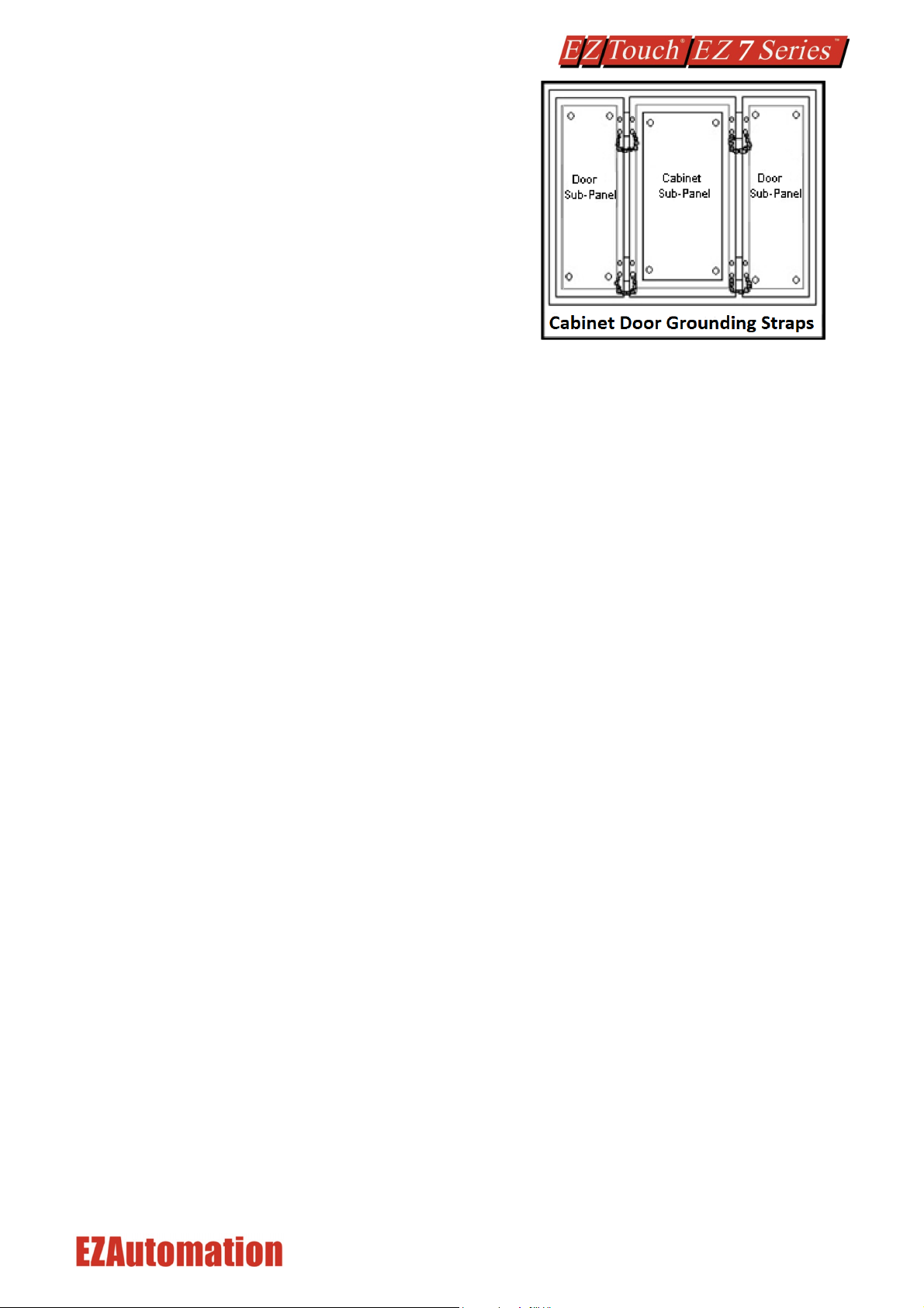
Equipment cabinets usually incorporate one or two doors and/or hinged cabinet panels. Relying on
door hinges and swinging panels for a good metallic bond between hinged parts and the main body of
the cabinet does not insure adequate grounding. Instead, the use of ground straps is
recommended. It is vital for the reliable operation of any electronic device to have any of its metallic
surfaces well ground to Earth. This not only provides for safe operation, it will also drain out any
conducted RFI to Earth, away from the CPU's signal ground.
Shielding from RFI
Shielded Cables
Power cables, I/O cables or wiring, and communication cables should all be separate so that they do
not couple the conducted RFI on any of these wires/cables. Another path for RFI into the PLC is
through its RS232 port. Hence, the cables to this port must be shielded properly.
Equipment Cabinets
As mentioned, equipment cabinets typically incorporate one or two doors and/or hinged cabinet
panels. In addition, sub-panels may be utilized on those electronic controls and electromechanical
items that are mounted. The goal is to create a medium for mounting the equipment and ensure
grounding of the control’s chassis to it. However, the door hinges and swinging panels by themselves
are not enough to ensure adequate grounding.

9 / 31
Similarly, the equipment enclosures are generally either
painted or anodized. Mounting of painted or anodized
enclosures to like surfaces also does not ensure good
metallic contact between the equipment chassis and
cabinet. It is imperative that the equipment chassis are
grounded such as through the use of grounding straps as
illustrated below.
Cabinet Wiring
The wiring of the EZ7 Series HMI to the “field” outside the cabinet must be by design. The wiring
cannot be random in order to get the various points of the cabinet and the “field” electrically
connected. Below are some general rules that apply in most situations:
Provide a separate power source to electronic controls and keep this power bus away from any I/O
power.
The cabinet should be wired with a safety ground (the main safety ground wire gauge is determined
by the cabinet’s total current consumption) and in accordance with all electrical code requirements.
Once the cabinet doors, stationary sub-panels and swing-out sub-panels have been “strapped” to the
main cabinet, it is not necessary to run safety ground wires from the equipment chassis terminals to
the main safety ground connection.
The safety ground terminal of each component can, and should be, connected with the shortest wire
possible, to the cabinet or sub-panel frame.
Plan the wiring routing. Keep all switched power in separate ducts and if there is AC and DC power
being switched, keep the wiring of each branch separate from all wires and cables carrying low level
signals.
Keep all three phase power outside of the cabinet, but if it becomes necessary, keep the runs as short
as possible and maintain the maximum possible distance between the three phase bus and all other
wiring.
Primary power leads to the control equipment (Base power terminals) should be made with a two
wire twisted cable with approximately 12 turns per foot. The length of these cables should be kept to
a minimum, and to the greatest extent possible, such cable runs should be kept separate from other
wiring.

10 / 31
4.2 DIMENSIONAL DRAWINGS
4.2.1 Overall Dimensions

11 / 31
4.2.2 T7C (7” Display) Mounting dimensions
4.2.3 T8C (8” Display) Mounting dimensions

12 / 31
4.2.4 T10C (10” Display) Mounting dimensions
4.2.5 T12C (12” Display) Mounting dimensions

13 / 31
4.3 MOUNTING INSTRUCTIONS
EZ7 comes in two parts:
1. HMI Processor Unit, mounted using 4 studs on backside of the control cabinet door
2. Display Unit, mounted on studs (number of studs depends on size).
A cable connects the two parts, which passes through a ¾” hole in the cabinet door.
To mount the unit, in summary:
•Mark location of all holes
•Drill holes for the back and front unit mounting studs. (Please note that the mounting holes for
the back unit require countersink holes.
•Drill ¾” hole for the cable.
•Connect display cable to the back side and mount the back side
•Thread the display cable through ¾” cable hole to the other side.
•Connect cable to front side and mount the front unit.
These steps are described below with pictures:
The EZ7 is stud mounted. All the necessary mounting hardware is provided with the unit. Both the
processor and the HMI screen have studs with nuts provided. Below is a full installation guide with
step by step instructions.
1. Use the provided screen with screw hole indicators to drill holes in your control cabinet.

14 / 31
2. Once all the holes have been drilled in the cabinet. Take the Processor Box and plug in the
provided HDMI cable into its connector port.
3. Then use the provided screws (6-32 Philips Flat head ½” length. (X 4),Screw driver – Philips #2 )
to install the Processor Box to the inside of the Control Cabinet. Also make sure that the HDMI
cable is pulled through the large middle hole.

15 / 31
1) Now connect the HDMI cable to the HMI screen, make sure that the cable is pulled through
the large middle hole.
2) Now insert all studs through their respective holes, and use provided nuts (Hex-head nut, size
10-32 requiring 3/8” nut driver/wrench) to secure the front to the cabinet.
3) When looking from bottom or top the screen should look like the image below.

16 / 31
PORTS AND WIRING
Pin
Number Connection
1
Chassis GND
2
PLC TXD (RS-232C)
3
PLC RXD (RS-232C)
4
+5V (100Ω)
5
Logic GND
6
LE
7
PLC CTS (RS-232C)
8
PLC RTS (RS-232C)
9
RXD+ (RS-422A)
10
RXD- (RS-422A)
11
TXD+ (RS-422A)
12
TXD- (RS-422A)
13
Terminating Resistor
(connect to pin 9)
14
NC
15
NC
Power: 24 VDC
1
Positive
2
Negative
3
Earth GND
Indicator Light at the backside of the unit
Flashes Red, then continuously Green
Power connected, Normal Operation
Blinking Red / Continuously Red
Some Panel Issue has occurred. Please try a power cycle, if that does not
fix the issue please contact Tech Support.
No Light
Power source not connected or inadequate
15 Pin D-Sub Serial
RS232/422/485 PLC Port
Use it to connect PLCs
serially. EZAutomation
offers cables for most PLCs
9 Pin D-Sub Serial
Programming Port
RJ45-Ethernet
connector
Micro SD card
Connector
Display Cable
Connector for
connecting FRONT unit
3-Terminal Power
Connector
USB Type B for
Programming
USB Type A for flash
drives

17 / 31
QUICKSTART
System diagram shown in introduction is repeated here. As shown, EZTouch Editor is required to program EZ7.
This is a common editor software for all EZTouch Families of panels.
Pre-requisite- Make sure you have everything you need:
This is what you will need to get started:
•EZ7 HMI Unit
•A PC Running Windows 7 or Windows 10 with EZTouch Editor Programming Software*
installed
•Proper cable to connect the PC to EZ7 Panel for project transfer and monitoring:
oRS-232C Programming cable (P/N EZ-PGMCBL) (or make your own) *, and/or
oUSB Type A to Type B cable, and/or
oEthernet cable (Ethernet IP must be setup before using Ethernet connection)
•24VDC Power Supply*
•Optionally, your plc and connecting cable
*These accessories have to be purchased separately
Follow these steps to get started:
1. Please connect power to the unit, and (optionally) connect your PLC.
2. If not already done, please Install EZTouch Editor on the PC. See below.
3. Run EZTouch Edit and start creating project
4. Transfer the project to the panel and start working with screens.
6.1 EZTOUCH EDITOR
If you already have EZTouch Editor installed, please ignore this section.
EZTouch Editor software is used to program all EZTouch Panels. This allows you to move projects from
one family to another easily. If you don’t have a copy of the editor, please acquire one. EZTouch Editor
is distributed as a single setup file, typically names as EZTouch Editor x.x.x (FULL).exe, where x.x.x is
version number of the software.
To install, just run the file, and follow on-screen instructions. For more information on the editor
please refer to the help in software and the EZTouch Editor User Manual (download from website)
Serial or Ethernet or USB Connection
Serial or Ethernet Connection
PC running
EZTouch Editor
EZ7 HMI
PLC or
Controller

18 / 31
6.2 CREATE A PROJECT
This section outlines the basics of creating a project using the EZ-PANELEDIT software. Further
programming information for the EZ7 Series HMI is located in the EZ Touch Editor Software Manual
and the EZ PLC Software Manual.
Launch your EZTouch Editor and select how you would like the program to link to the EZ7 Series HMI
unit. For this scenario, you can select “Open / New Project”. This will enable you to create a program
without having the EZ7 Series HMI unit connected through the serial port or the Ethernet connection.
This example will use the demonstration driver which does not require an external PLC.
Note: The steps outlined below are based on the EZTouch Editor version 2.0.13 and may vary slightly
between versions.
4) Open the EZTouch Editor Software. You will see the Project Information screen, example
below.
5) Click on Open / New Project then enter a project name (e.g. Test). Then press enter.
6) Next select EZTouch in the radio buttons below Panel Family. Then select EZ7 Series from the
drop-down list. Then select the size of the panel you will use (7”, 8”, 10”, 12”)

19 / 31
7) Now under Protocol / PLC Model please select PLC Manufacturer of Demonstration. The rest
of the field will populate.
8) Click “Click to Start Designing” to launch the editing software program. The Main Project
Window will then appear showing Panel sides to the program.
9) On the right side of the screen find Buttons and click on the icon. The screen below will
appear. Enter START for Tag Name. Click OK.
10) The “Add New Tag Details” screen will ask for tag address. Please enter R501/0 for the
address. Then click OK. Note: All previous address are used and could cause unpredictable
behavior.
This manual suits for next models
8
Table of contents