Hardware Overview for WR
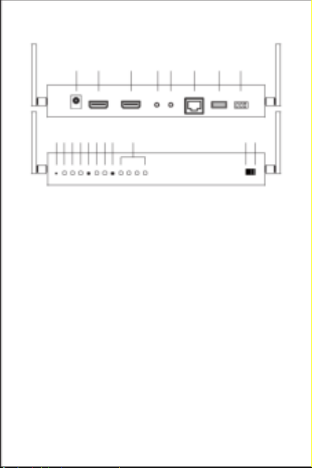
1. DC IN port: 12V/1A power supply is required.
2. HDMI OUT port: Connect to the monitor for display.
3. AUX OUT port: Output audio to the speaker connected. Note that HDMI
OUT port receives audio signal simultaneously.
4. IR IN port: Input IR signal for remote control.
5. RJ45 port: Connect to router or switch with LAN cable for bridge. Only for
specific settings like firmware upgrade and CMS system control.
6. USB K/M: Support external keyboard and mouse for remote control.
7. RS232: Input RS232 signal for remote control.
8. Reset hole: Long press to reset to factory default settings.
9. PWR light: Lighting when power is supplied.
10. LINK light: Flashing when data is transmitting.
11. STA light: Lighting when HDMI cable is connected.
12. MODE button: Click to switch display mode (lighting for mode 1), and long
press to optimize the resolution.
13. Mode 1 light (Display mode): Light off indicates graphic mode with shorter
latency, and light on indicates video mode with less package lost rate.
14. Mode 2 light (Channel bit): Light on indicates channel adjustment is for
high-bit channel, while light off indicates channel adjustment is for low-bit
channel.
15. ID button: Click to switch channel ID, and long press to switch between
high-bit and low-bit channel adjustment (lighting for mode 2).
16. Channel signal: The channel number is the sum of what the light-on
signals represent.
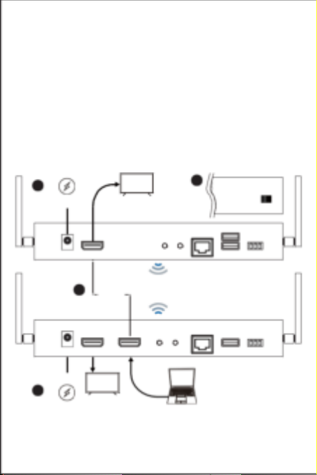
17. Switch mode: Display the screen of WT with the same channel ID.
18. Splitter mode: Direct connection to WT for 1 to 1 extending display or 1 to N
multicast. No channel ID should be set.