Newport 1807 User manual

USER ’S GUIDE
80-MHz Balanced
Photoreceivers
Models 1807 and 1817
phone: (877) 835–9620
e-mail: [email protected]
www.newport.com
These photoreceivers are sensitive to
electrostatic discharges and could be
permanently damaged if subjected to any
discharges. Ground yourself adequately
prior to handling these detectors or making
connections. A ground strap provides the
most effective grounding and minimizes
the likelihood of electrostatic damage.

Warranty
Newport Corporation guarantees its products to be free of defects for
one year from the date of shipment. This warranty is in lieu of all other
guarantees, expressed or implied, and does not cover incidental or
consequential loss. Information in this document is subject to change
without notice.
Copyright 2001-1998, 2013, Newport Corporation. All rights reserved.
The New Focus logo and symbol are registered trademarks of
Newport corporation.
Document Number 9009991 Rev. D

80-MHz Balanced Photoreceivers 3
Contents
Introduction 5
Overview. . . . . . . . . . . . . . . . . . . . . . . . . . . . . . . . . . . . . . . . . . . . . . 5
Operation 7
Quick Start . . . . . . . . . . . . . . . . . . . . . . . . . . . . . . . . . . . . . . . . . . . . 7
General Principles. .. . . . . . . . . . . . . . . . . . . . . . . . . . . . . . . . . . . 9
Customer Service 13
Technical Support . . . . . . . . . . . . . . . . . . . . . . . . . . . . . . . . . . . . 13
Service . . . . . . . . . . . . . . . . . . . . . . . . . . . . .. . . . . . . . . . . . . . . . . 13
Specifications 14

4
This page was intentionally left blank.

80-MHz Balanced Photoreceivers 5
Introduction
Overview
The Newport Model 18X7 balanced photoreceiver
consists of two matched photodiodes and a high-
speed amplifier that generates an output voltage
proportional to I2 - I1, the difference between the
photocurrents in the two photodiodes.
The Quick Start and General Principles sections
below give an overview of setting up the
photoreceiver and understanding its principles
and design. The sections that follow give detailed
information about the technical specifications.

6
This page was intentionally left blank.

80-MHz Balanced Photoreceivers 7
Operation
Quick Start
The following parts are supplied with the
Model 18X7 balanced photoreceiver:
•Model 0923 M8B-to-M8B connector power cable
•Model 0924 M8B-to-banana plug power cable
•Model 1225 SMA-to-BNC adapter
The steps below describe the basics of setting
up and using the photoreceiver.
1. Use one of the supplied power cables to connect
the photoreceiver to a ±15-volt power source that
can supply 200 mA (the minimum current
requirement for DC power supply is 100mA).
8
For the Newport Model 0901 power supply, use
the 0923 M8B-to-M8B cable. For other power
supplies, use the 0924 M8B-to-banana plug
power cable.
When using the M8B-to-banana plug cable, take care
to hook up the banana plugs as follows to avoid
damaging the photoreceiver: Red = +15 V, Black =
-15 V, Green = Ground.
2. Mount the photoreceiver to your optical table.
3. Connect the optical source to both optical inputs.
The FC adapter for both types of 18X7
photoreceiver will accommodate either multi-mode
or single-mode fiber.
To prevent saturation of the amplifier, keep the
difference between the input powers less than the
saturation power shown in Specifications.
The optical power must remain below the absolute
maximum power listed in Specifications. Exceeding the
maximum power may damage the photodiode and the
amplifier.
4. Individually block each photodiode input to check
and adjust the optical inputs so that the output
voltages are in the desired –2.5 to +2.5 V range
(with 50 Ω load).
Illuminate both diodes simultaneously and use the
output to fine-tune the optical power balance
between the two diodes while observing voltage
on a digital voltmeter or other low-frequency
measurement device.

80-MHz Balanced Photoreceivers 9
5. Finally, connect the output SMA connector to the
desired load or instrument via a 50-Ω coaxial
cable.
General Principles
The Newport Model 18X7 balanced photoreceiver
consists of two matched photodiodes and a high-
frequency amplifier that generates an output voltage
proportional to I2 - I1, the difference between the
photocurrents in the two photodiodes. Figure 1 shows
a functional block diagram of the balanced
photoreceiver, and Figure 2 shows the mechanical
drawing.
Figure 1:
Functional
block diagram
of the Model
18X7
+V
-V
D1
D2
TIA OP AMP
OUTPUT
Figure 2:
Mechanical
drawing of the
balanced
photoreceiver
Unless otherwise noted, dimensions are in inches with metric dimensions in mm in brackets.

10
Responsivity and Input Power
The Model 1807 uses a matched pair of silicon
photodiodes, while the Model 1817 uses a matched
pair of InGaAs photodiodes. Figure 3 shows the
typical responsivity of the photodiodes.
Figure 3:
Typical
responsivities
of the
photodiodes in
Model 1807
(top) and
Model 1817
(bottom) 0
0.1
0.2
0.3
0.4
0.5
0.6
200 400 600 800 1000 1200
Wavelength, nm
Responsivity, A/W
0
0.2
0.4
0.6
0.8
1
800 1000 1200 1400 1600 1800
Wavelength, nm
Responsivity, A/W
Gain, Bandwidth and Noise
The amplifier is a low-noise device with low output
impedance. The amplifier’s transimpedance gain is
40 V/mA when driving a 50-ohm load.
Depending on wavelength (see typical responsivity
curves in Figure 3 above), the amplifier will reach
saturation levels when the difference between the
two photo inputs is approximately 110 uW (for
responsivity of 0.5 A/W). For a high-impedance
load, the maximum output voltage will be
80-MHz Balanced Photoreceivers 11
approximately ±4 V before the amplifier is saturated.
For a 50-Ω load, the maximum output voltage will
be approximately ±2 V before saturation.
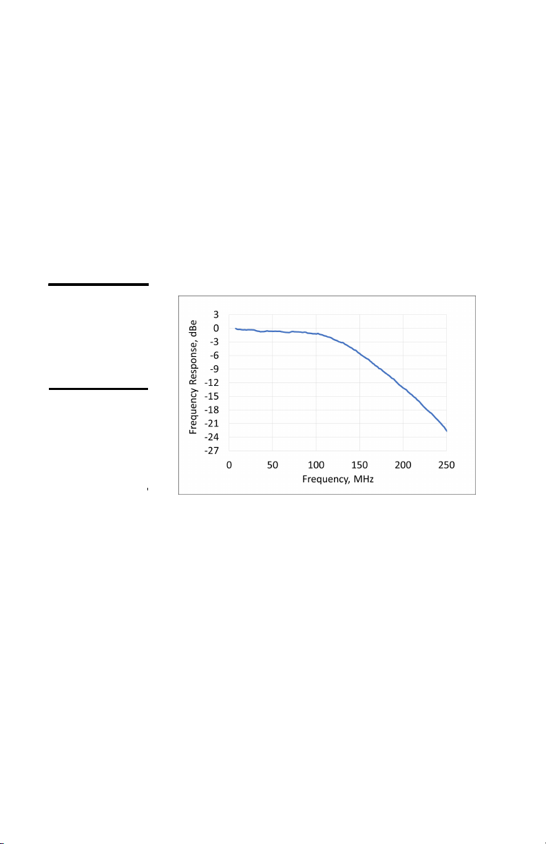
The 3-dB bandwidth is typically in excess of 80 MHz
for the Model 18X7 photoreceivers. See the typical
frequency response plot in Figure 4.
To detect a weaker signal, you can reduce the noise
by adding an electronic bandpass filter at the output
of the photoreceiver, or consider the 125 kHz
bandwidth Nirvana Auto balanced photoreceiver,
Model 20X7, or use lock-in amplifier and chopper
techniques to further narrow your measurement
bandwidth.
Figure 4:
Typical
Frequency
Response for
the 18X7
Products
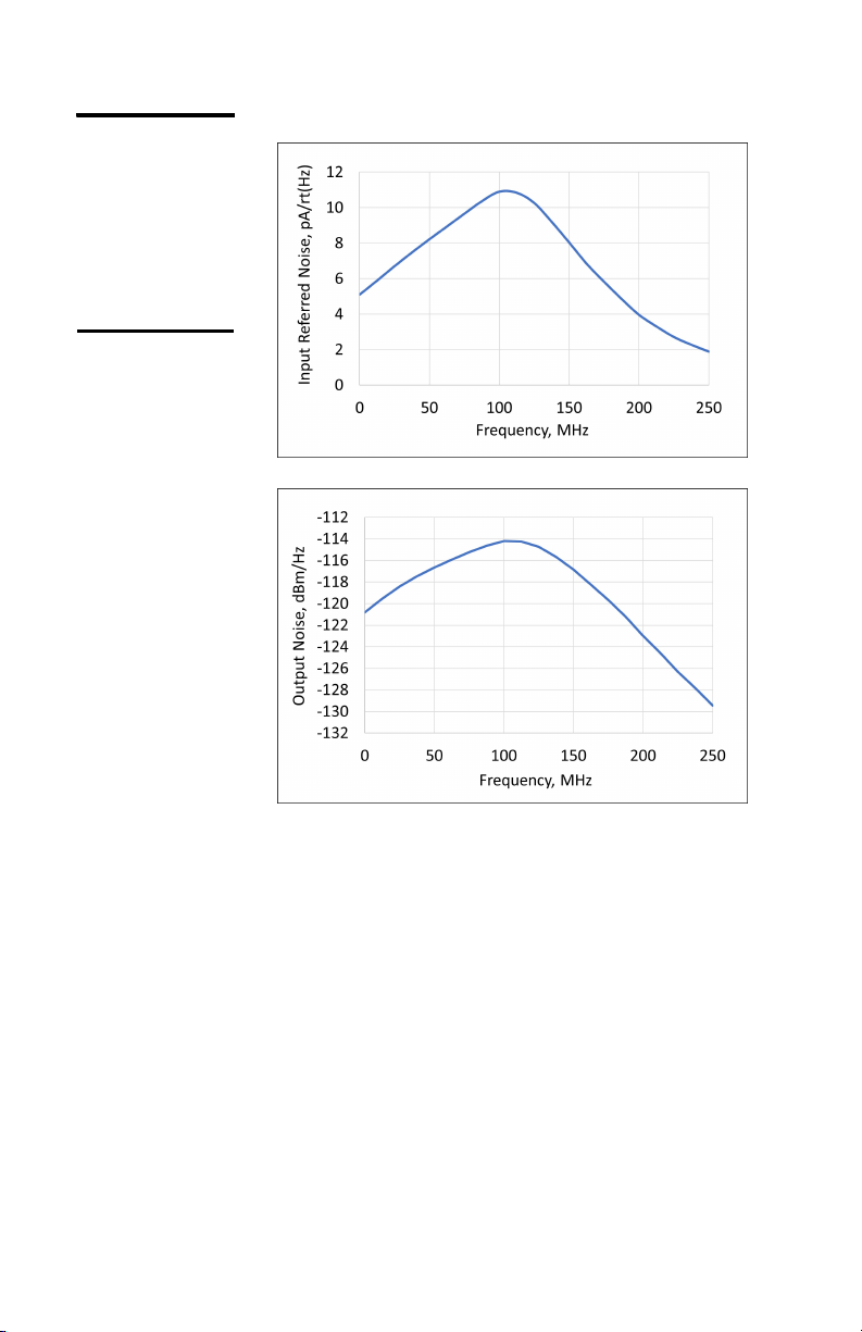
The noise for the 18X7 family is 5 mVrms when
measured on a >250-MHz, 50-ohm oscilloscope. For
additional information on 18X7 noise performance,
see the typical Input Referred Noise and typical
Output Noise plots in Figure 5 on the next page.
12
Figure 5:
Typical Input
Referred Noise
(top) and
typical Output
Noise (bottom)
for the 18X7
products

80-MHz Balanced Photoreceivers 13
Customer Service
Technical Support
Information and advice about the operation of any
Newport product is available from our technical support
engineers. For quickest response, ask for “Technical
Support” and know the model number and serial number
of your photoreceiver.
Hours: 8:00-5:00 PST, Monday through Friday (excluding
holidays)
Phone: 1-877-835-9620
Support is also available by email and chat
Chat: Connect with us at www.Newport.com
Email: [email protected]
We typically respond to email within one business day
Service
In the event that your photoreceiver malfunctions
or becomes damaged, please contact Newport for
a return merchant authorization (RMA) number
and instructions on shipping the unit back for
evaluation and repair.

14
Specifications
Model 1807 Model 1817
Wavelength Range 320–1000 nm 900–1700 nm
3-dB BandwidthDC–80 MHz DC–80 MHz
Common Mode
Rejection Ratio
25 dB typical 25 dB typical
Conversion Gain 2x10⁴ V/W4x104 V/W
Typical Max. Responsivity 0.5 A/W @760nm 1.0 A/W @1550nm
40 V/mA
Output Impedance 33 Ω 33 Ω
CW Saturation Power
(Differential) (µW)
110 @ 760 nm 55 @ 1550 nm
Max. Differential Power
(Damage Threshold) (mW)
10 @ 760 nm 5 @ 1550 nm
Max. Power per Photo-
diode (Damage
Threshold) (mW)
10 @ 760 nm 5 @ 1550 nm
Detector Material/Type Si/PIN InGaAs/PIN
Detector Active Area 0.4 mm diameter 0.15 mm diameter
Optical InputFC or free space
Electrical Output SMA SMA
Package Dimension 3.00 x 2.86 x
2.07 inches
3.00 x 2.86 x
2.07 inches
Power Supply
Requirement
± 15 V DC, <200
mA (Model 0901
recommended)
± 15 V DC, <200
mA (Model 0901
recommended)
Integrated Noise 5 mVrms5 mVrms
FC or free space
40 V/mA
Transimpedance Gain*
* When driving a 50 Ω load
This manual suits for next models
1
Table of contents
Other Newport Receiver manuals

Newport
Newport NIRVANA User manual

Newport
Newport 1801 User manual

Newport
Newport 1580-A User manual

Newport
Newport 1607-AC User manual

Newport
Newport 2107 User manual

Newport
Newport 1601 User manual

Newport
Newport 2151 User manual

Newport
Newport 2051 User manual

Newport
Newport 2007 User manual

Newport
Newport zW Series User manual
Popular Receiver manuals by other brands


Velleman
Velleman ED85009 user manual

Kramer
Kramer PT-573 user manual

Williams Sound
Williams Sound SoundPlus WIR TX300 Installation guide & user manual

Huawei
Huawei OptiX RTN 910A V100 Quick installation guide

Appareo
Appareo Stratus 3 pilot's guide

Sherwood
Sherwood Newcastle HSB-6501 operating instructions


