Ezee Glow Mini Zara User manual

1
Mini Zara, Zara, Grand Zara and XL Zara Electric Fire Range
OWNERS MANUAL
Model Numbers: MZEZAWHBL42, MZEZAWHBL50, MZEZAWHBL60, MZEZAWHBL72
AC 220-240V, 50Hz 1400-1600W
WARNING
Please read the entire owner’s manual, including all safety information,
before plugging in or using this product. Failure to do so could result in fire,
electric shock, or serious personal injury.
CAUTION
Keep the owner’s manual for future reference. If you sell or give this product
away, make sure this manual accompanies this product.
@ezeeglow
@ezeeglowelectricfires
Rev G
Be sure to upload your fire image using #ezeeglow and tag Ezee
Glow on Facebook or Instagram to feature on our social media!

2
IMPORTANT SAFETY INFORMATION!
WARNING
When using electrical appliances basic precautions should always be followed to reduce the risk of fire,
electric shock and injury to persons, including the following:
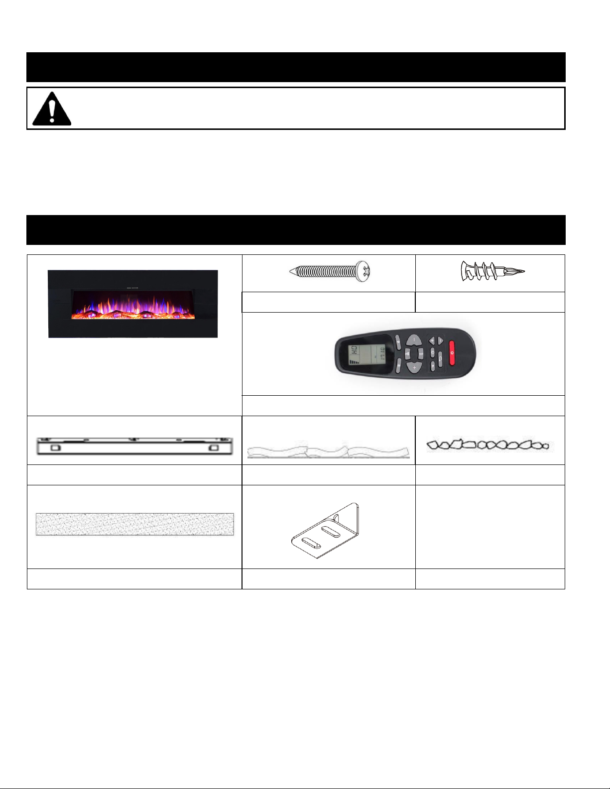
⚫Read all instructions before using this heater.
⚫This heater is hot when in use. To avoid burning, do not touch the hot surface. If provided, use handles when
moving this heater. Keep combustible materials, such as furniture, pillows, bedding, paper, clothes, and curtains at
least 1 m from the front of the heater and keep them away from the sides and rear. In order to avoid overheating,
do not cover the heater.
⚫Extreme caution is necessary when any heater is used near children or the infirm and whenever the heater is left
operating and unattended.
⚫Always unplug heater when not in use.
⚫Do not operate any heater with a damaged cord/ plug, after the heater malfunctions or has been damaged in any
manner. Return heater to authorized service facility for examination, electrical/ mechanical adjustment, and repair.
⚫Indoor use only, do not use outdoors.
⚫This heater is not intended for use in bathrooms, laundry areas or similar indoor locations. Never locate heater
where it may fall into a bathtub or other water container.
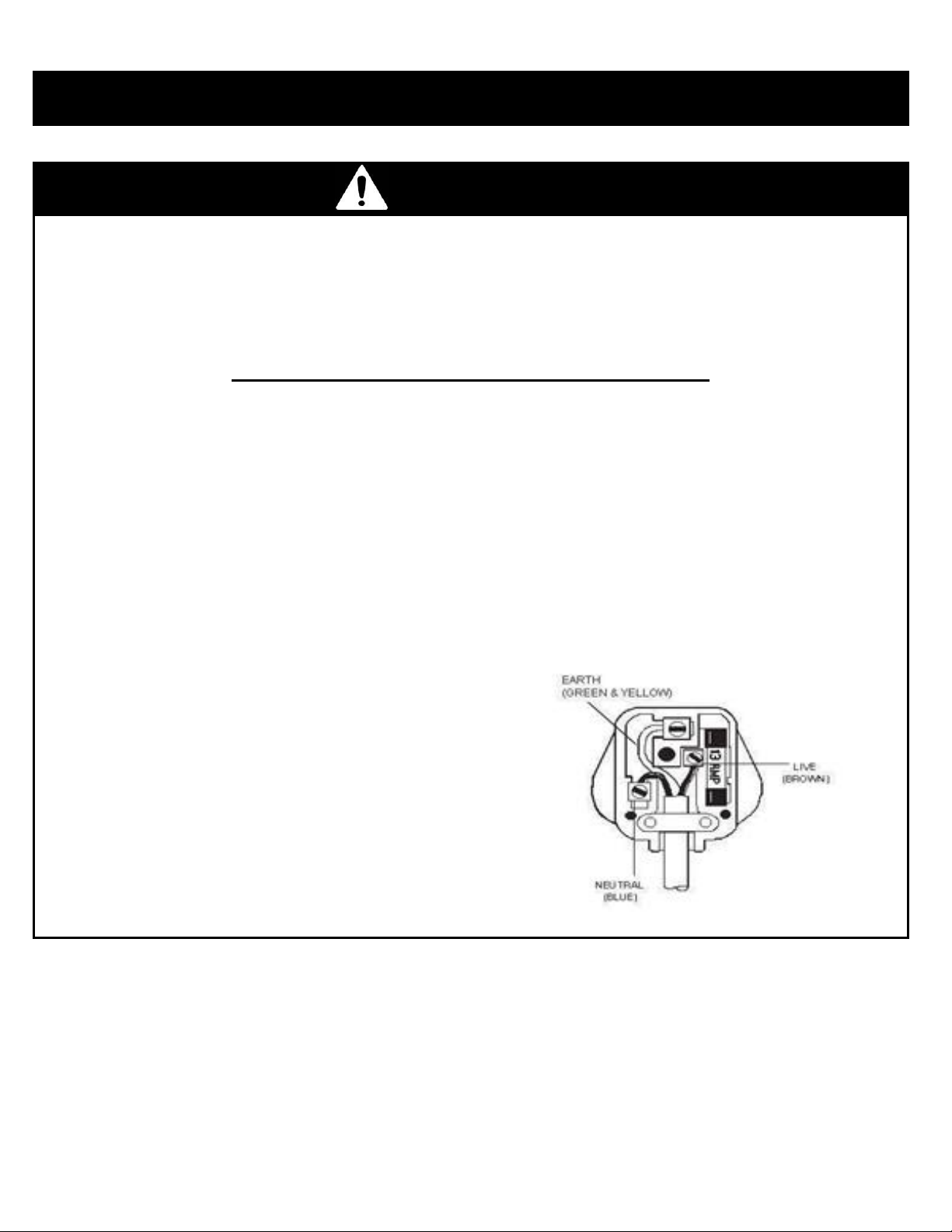
⚫Do not run cord under carpeting. Do not cover cord with throw rugs, runners, or similar coverings. Arrange cord
away from traffic areas, where it will not be tripped over.
⚫To disconnect heater, turn controls to off, then remove plug from outlet.
⚫Do not insert objects into any ventilation or exhaust openings, as this may cause an electric shock, fire, or damage
to the heater.
⚫To prevent a possible fire, do not block air intakes or exhaust in any manner. Do not use on soft surfaces like a
bed, where openings may become blocked.
⚫The heater has hot, arcing parts inside. Do not use it in areas where flammable liquids are used/ stored.
⚫Use this heater only as described in the manual. Any other use not recommended by the manufacturer may cause
fire, electric shock or injury to persons.
⚫DANGER - HIGH Temperatures may be generated under certain abnormal conditions. Do not partially or fully
cover/ obstruct the front of this heater.
⚫Do not install heater directly below a power socket outlet.
⚫This appliance can be used by children aged from 8 years and above and persons with reduced physical, sensory
or mental capabilities or lack of experience and knowledge if they have been given supervision or instruction
concerning use of the appliance in a safe way and understand the hazards involved. Children shall not play with
the appliance. Cleaning and user maintenance shall not be made by children without supervision. Children of less
than 3 years should be kept away unless continuously supervised.
⚫CAUTION: In order to avoid a hazard due to inadvertent resetting of the thermal cut-out, this appliance must not
be supplied through an external switching device, such as a timer, or connected to a circuit that is regularly
switched on/ off by the utility.

3
WARNING
WARNING: This heater is not equipped with a device to control the room temperature. Do not use this heater in
small rooms when they are occupied by persons not capable of leaving the room on their own, unless constant
supervision is provided.
·
CAUTION —Some parts of this product can become very hot and cause burns. Particular attention
must be given when children and vulnerable people are present.
ELECTRICAL CONNECTIONS –UK PLUG WIRING INSTRUCTION
•
If the plug must be changed because it is not suitable for your socket, or due to damage, please follow
the wiring instructions shown below.
•
The wires in the mains lead are coloured in accordance with the following code:
BROWN: LIVE (L)
BLUE: NEUTRAL (N)
GREEN/YELLOW: EARTH (E)
As the colours of the wires in the mains lead of this appliance may not correspond with the
coloured markings identifying the terminals in your plug, please see below:
•
The BLUE wire is the NEUTRAL and must be connected to the
terminal which is marked with the letter N or coloured BLACK.
•
The BROWN wire is the LIVE and must be connected to the
terminal that is marked with the letter L or coloured RED.
•
The GREEN/YELLOW must be connected to the terminal which
is marked E or the earth symbol or coloured GREEN or
GREEN/YELLOW.
•
Always ensure that the cord grip is positioned and securely
fastened.
•
WARNING: THIS APPLIANCE MUST BE EARTHED.
•
If a 13A (BS1363) fused plug is used it must be fitted with
a BS1362 13A fuse. If in doubt consult a qualified
electrician.
IMPORTANT SAFETY INFORMATION!

4
Install preparation
This product includes a GLASS panel. Use extreme caution when handling.Failure to
do so could result in personal injury or property damage.
Remove all parts and hardware from the carton and place them on a clean, soft, dry surface. Check the
parts list to make sure you have all the parts you need. Please recycle all packaging material at your local
recycling center.
You will need the following tools (not included): Phillips screwdriver, stud finder, spirit level, tape
measure, electric drill and drill-bit set.
Parts and Hardware
A –Electric fire
B –Wood Screws
C –Drywall anchors
D- Remote Control
E –Wall bracket
F- Decorative Log-set
G –Decorative Pebbles
H –Fuel-bed tray
I- ‘L shape’metal bracket

5
Dimensions
Product dimensions listed in mm and [inches].
Mini Zara:
Zara:

6
Grand Zara:
XL Zara:

7
Installation Overview
Wall Mounted Installation
Rear View ofFireplace
Minimum 0”
(0cm)
0”
(0cm)
0”
(0cm)
Minimum11.8”
(30cm)
Find a safe location:
Minimum clearance on each side:
0” (0cm).
Minimum clearance below: 11.8” (30cm).
Minimum clearance above: 0” (0cm).
Minimum clearance from the front: 3feet
(90 cm).
Choose a location near an outlet so an
extension cord is not required.
DO NOT position the unit directly below a
poweroutlet.
See Safety Information on pages 2 and3
for warnings about safe placement, safe
installation, and proper use of this
product.
NOTICE
The wall mount fasteners included with this fire are for use ONLY with a wood-
framed wall covered in drywall. For concrete walls, cinder blocks, or other wall
types, consult a professional for the best attachment methods.
NOTICE
Due to the additional weight, the XL Zara must be wall mounted using the two wall
brackets provided.
ALWAYS unplug this fire heater before assembly, cleaning, or before
relocating. Failure to do so could result in electric shock, fire, or personalinjury.
AVOID INJURY and DAMAGE! Three screws need attached directly into wall
studs and additional screws must be attached using drywall anchors to assist.

8
Due to the many different materials used on different walls, it is highlyrecommended
that you consult a competent tradesman before you install this appliance on thewall.
A. Select a location that is not prone to moisture and is located at least 36" (914mm)
away from combustible materials such as curtain drapes, furniture, bedding, paper,
etc.
B. Have two people hold the appliance against the wall to determine the final location.
C. Place unit face down on a soft, non-abrasive surface. Remove the wall bracket(s)
from the back of the unit by removing the relevant screws.
D. Mark out bracket(s) location using a spirit level to assist, then mount the bracket(s)
to the wall using the supplied screws. The bracket(s) MUST have the hooks facing
upward.
NOTE: It is strongly recommended that the wall bracket be screwed into wall
studs where possible. If wall studs cannot be used, ensure that eight plastic
anchors are used to affix each bracket to the wall andeach bracket is
adequatelysecured.
E. With the wall bracket(s) installed, lift the appliance,and guide the bracket hooks into
the two (four for XL Zara) slots on the back of theappliance.
F. Check the appliance for stability ensuring that the bracket(s) will not pull free from
the wall. Finally, skip to page 10 and carry out the L-bracket install to finish wall
installation.

9
33cm
Wall
30cm
Wood screws
32.5cm
33cm
D

10
Wall Securing BracketInstallation
Following wall bracket installation, the small “L” shape mounting bracket (page 6 –item
‘D’) needs attached to secure the fire to thewall. See below guide and illustration:
G. Remove the two screws on the bottom of the fire box, then grab the L-shape
mounting bracket.
H. Attach one side of the bracket to the bottom of fire using two screws, attach the
other side to the wall using one Drywall anchor (C) & screw (B) to secure the fire
to the wall.
Drywall

11
(B) Wall
anchor
locations
WALL RECESS INSTALLATION
STEP A. Select a dry wall for fire recess. Select recess size using the illustration above and
the corresponding columns W1, H1 and D1 below:
Product Name
W1
H1
D1
W2
H2
Mini Zara
90.5cm
48.26cm
12cm
92.5cm
40cm
Zara
111cm
48.26cm
12cm
113cm
40cm
Grand Zara
136.2cm
48.26cm
12cm
138.2cm
40cm
XL Zara
166.8cm
48.26cm
12cm
168.8cm
40cm
STEP B. Mount four wall anchors in each corner of the wall using the illustration above
and the corresponding columns W2 and H2 above.
(A) Wall recess
dimensions
W1
H1
D1
Note –Ensure there
is at least a 1.5cm
gap between top of
the fire box and top
of recess, for
adequate ventilation.

12
STEP C. Lift the fire into
the recess and attach
four screws through the
holes in the corners of
the fire, into the
previously fitted dry wall
mounts. The fire is now
secured to the wall.
STEP D. Next, attach
the front glass by lifting
it flush against the fire
and locating the hooks
on the back of the front
glass, on to the inside
catches of the fire, see
figure to the left, detail
view 2 for illustration.
Fixed glassparts

13
Fuel-bed Effect Installation
A. For both options, the front glass must be removed, and the appliance mounted in its final
location before the log effect or pebbles are installed. Simply remove the two silver-coloured
screws on each side of the fire and lift the front glass up then out to remove it. Set it aside for
later.
B. Next, the clear glass screen needs removed. Pay attention to each side of the glass screen,
there’s a metal bracket on each side with two screws each, these keep the glass screen in
place. Remove the two screws on each side and remove the brackets, making sure to support
the glass when removing the final screw. Simply pull the glass out and set it aside for later.
C.If you want your fire with the log effect, remove the log effect from its packaging and reverse
the order of steps A and B, completing the fuel-bed installation, see Figure 1. If you prefer the
pebble effect, remove the log effect from the fire and place the media tray holder (H) onto the
bottom tray. Next, carefully place the pebbles (G) onto the bottom tray as illustrated below.
Apply an even layer from side to side, see Figure 2 and Figure 3. Reverse the order of steps A
and B, completing the fuel-bed installation.
Figure 1.
Figure 2. Figure 3.
Note:
The appliance must be installed in its final location before the crystals or artificial logs are installed.

14
Operation
Please read the entire owner’s manual, including all safety information, before
plugging in or using this product. Failure to do so could result in fire, electric shock, or
serious personal injury.
Power
Plug the power cord into a 220-240V 50Hz outlet (see IMPORTANT SAFETY INFORMATION on
Pages 2 and 3). Make sure the outlet is in good condition and the plug is not loose. NEVER exceed
the maximum amperage for the circuit. DO NOT plug other appliances into the same circuit.
Methods of Operation
The electric fire can be operated by the control panel located on the front of the unit or the remote
control. See figures below.
Before operating, please review the IMPORTANT SAFETY INFORMATION on Pages 2 and 3.
Control panel
Remote control

15
Control Panel Operation
BUTTON
FUNCTION
ACTION & INDICATION
ON: Enables control panel functions and
remote control. Turns on flame effect.
OFF: Disables control panel functions and
remote control. Turns off flame effect.
1. Press once, Indicator light turns on.
Power turns on. All functions enabled.
2. Press again, Flame effect turns off.
Power and all functions turn off.
BRIGHTNESS button: Adjusts brightness.
1. Press once, Indicator light turns on.
Brightness changes.
1. Press again, until desired brightness is
selected.
FLAME button: Adjusts flame and fuel-
bed colour.
NOTE: Flame effect stays on until power
button is turned off. Flame effect must be
on for heater to turn on.
1. Press once, Indicator light turns on.
Flame and fuel-bed colour changes.
2. Press again, until desired colour is
selected.
HEATER button: Turns heater on and off.
NOTE: The heater only works when the
flame effect is on. If the flame effect is off,
the heater will not turn on.
NOTE: To prevent overheating, the heater
blows cool air for 10 seconds before the
heater turns on, and after it turns off.
NOTE: Heater overrides room temp
control.
1. Press once, Indicator light turns on.
Fan blows cool air for 10 seconds. Low
heater (H1) turns on and blows warm air.
2. Press again, Indicator light remains on.
High heater (H2) turns on and blows hot
air.
3. Press again, Indicator light turns off.
The fan blows cool air for 10 seconds,
then turns off.
TIMER button: Turns heat on for a certain
time period.
P 1. Press once, Indicator lights up.
Heat on time goes to 30 minutes.
2. Press again, until desired time length is
reached.

16
Remote Control Operation
BUTTON
FUNCTION
ACTION & INDICATION
ON: Enables control panel functions and
remote control. Turns on flame effect.
OFF: Disables control panel functions and
remote control. Turns off flame effect.
1. Press once, Indicator light turns on.
Power turns on. All functions enabled.
2. Press again, Flame effect turns off.
Power and all functions turn off.
FLAME button: Adjusts flame and fuel-
bed colour.
NOTE: Flame effect stays on until power
button is turned off. Flame effect must be
on for heater to turn on.
1. Press once, Indicator light turns on.
Flame and fuel-bed colour changes.
2. Press again, until desired colour is
selected.
BRIGHTNESS button: Adjusts brightness.
1. Press once, Indicator light turns on.
Brightness changes.
2. Press again, until desired brightness is
selected.
HEATER button: Turns heater on and off.
NOTE:The heater only works when the
flame effect is on. If the flame effect is off,
the heater will not turn on.
NOTE: To prevent overheating, the heater
blows cool air for 10 seconds before the
heater turns on, and after it turns off.
NOTE: Heater overrides room temp
control.
1. Press once, Indicator light turns on.
Fan blows cool air for 10 seconds. Low
heater (H1) turns on and blows warm air.
2. Press again, Indicator light remains on.
High heater (H2) turns on and blows hot
air.
3. Press again, Indicator light turns off.
The fan blows cool air for 10 seconds,
then turns off.
TIMER SETTINGS ON REMOTE CONTROL
: Timer: Displays current day, time, and week. Press to
enter or confirm timer settings.
: Settings: Press to move to next step. Press to confirm
week timer.
: Back: Press to clear current settings. Press to return to the
previous step.
: Up and Down: Press to increase/ decrease certain settings.

17
LCD Screen
Weekday
Mon, Tues, Wed, Thurs, Fri, Sat, Sun
Note: The functions can
only be adjusted when the
related letters or digits are
flashing.
Note: Calibrate the timer
to current time before
entering the weekly
settings.
Time Display
Current Time / Timer From 00:00 to 24:00
NOTE: 00-12:00 is AM / 13:00-24:00 is PM
THERMO-STAT button: Turns heater on
and off to maintain room at a certain
temperature.
NOTE: Press & Hold the button for 5
seconds, the temperature setting will
switch from ℃to ℉. Same way from ℉
to ℃.
P 1. Press once, Indicator lights up.
Temperature goes to 18 ℃
2. Press again, until desired setting is
reached.
1 Set current day and time
1.
Press
once. When “MON” (Monday) begins flashing, useto select the current day.
2.
Press
. When the hour digits begin flashing, use to select the current hour.
3.
Press
again. When the minute digits begin flashing, use to select the current minute.
4.
Press
again. The current time is now set.
2 Set ON/OFF time and temperature on a weekly cycle
1.
Press
. When “MON” begins flashing, press 3 times. When “ON” begins flashing, use to select the
desired hour and minute to turn on the heater. Press at any time to clear the digits and shut down “ON”
timer.
2.
Press
. When “OFF” begins flashing, use to select the desired hour and minute to turn off the
heater.
Press at any time to clear the digits and shut down “OFF” timer.
3.
Press
again. When “18” begins flashing, use to select the desired temperature for Monday.
4.
Press
again. When “TUES”appears on the screen and “ON” begins flashing, use to select the
desired
hour and minute to turn on the heater forTuesday.
5.
Press
again. When “OFF” begins flashing, use to select the desired hour and minute to turn off
the
heater forTuesday.
note:
The timer can only be adjusted in 30-minute intervals (i.e. 00:00 - 00:30; 00:30 - 01:00, etc.)
note:
If the temperature was previously set, those digits will be shown instead of“18”.

18
6.
Press
again. When “18” beginsflashing, use to select the desired temperature forTuesday.
7. Repeat steps 1 to 6 to set the “ON/OFF” time and temperature for Wednesday, Thursday,Friday,
Saturday, and Sunday.
8.
Press
or to finish, ensuring to aim the remote control at the receiver, located in the middle of the
appliance. The appliance will “beep” once to confirm your settings have been saved successfully.
Open window warning
If the room temperature decreases by 10 degrees within 3 minutes, the appliance will assume there is an open window
nearby. In order to conserve energy, the heater will automatically switch from High Heat to Low Heat, or if the heater is
already at Low Heat, it will turn off completely.
When switching from High Heat to Low Heat, the appliance will beep 3 times and the digital display will flash “88” 3 times
before displaying the existing heating status.
When switching from Low Heat to Off, the appliance will beep 3 times and the digital display will flash “88” continuously.
Toreset the heating function, see “operating remote control” section.
NOTICE
When the heater is first turned on, a slight odour may be present. This is normal
and won’t occur again unless the heater is un-used for a long period of time.
NOTICE
To improve operation, aim the remote control at the front of the fire unit. DO NOT
press the buttons too quickly. Give the unit time to respond to each command.
Temperature Limiting Control
This heater is equipped with a Temperature Limiting Control. Should the heater reach an unsafe
temperature, the heater will automatically turn OFF. To reset:
1. Unplug the power cord from the outlet.
2. Turn the ON/OFF switch on the CONTROL PANEL to OFF. Wait 5 minutes.
3. Inspect the fire unit and make sure all vents are free from dust or lint. If they are clogged, use a
vacuum to clean the vent areas.
4. With the POWER switch in the OFF position, plug the power cord back into the outlet.
5. If the problem continues, have your outlet and wiring inspected by a professional.
Remote Control Battery Information
•This remote control uses Two AAA batteries (NOT included).
NEVER dispose of batteries in fire. Failure to observe this precaution may result in
explosion.Dispose of batteries at your local hazardous material processing center.

19
Care and Maintenance
Cleaning
ALWAYS turn the heater OFF and unplug the power cord from the outlet before
cleaning, performing maintenance, or moving the fire unit. Failure to do so could result in
electric shock, fire, or personal injury.
NEVER immerse in water or spray with water. Doing so could result in electric shock,
fire, or personal injury.
Metal:
•Buff using a soft cloth, slightly dampened with a citrus oil-based product.
•DO NOT use brass polish or household cleaners as these products will damage the metal trim.
Glass:
•Use a good quality glass cleaner sprayed onto the cloth or towel. Dry thoroughly with a paper
towel or lint-free cloth.
•NEVER use abrasive cleansers, liquid sprays, or any cleaner that could scratch the surface.
Vents:
•Use a vacuum or duster to remove dust and dirt from the heater and vent areas.
Plastic:
•Wipe gently with a slightly damp cloth and a mild solution of dish soap and warm water.
NEVER use abrasive cleansers, liquid sprays, or any cleaner that could scratch the surface.
Maintenance
Risk of electric shock! DO NOT OPEN any panels. Contact retailer before
conducting repair work.
ALWAYS turn the heater OFF and unplug the power cord from the outlet before
cleaning, performing maintenance, or moving the fire unit. Failure to do so could result in
electric shock, fire, or personal injury.
Electrical and Moving Parts:
•The fan motors are lubricated at the factory and will not require lubrication.
•Electrical components are integrated in the fire unit and are not serviceable by the consumer.

20
Problem
Possible Cause
Solution
Note
Fire not
turning on
Fire not plugged
in or switched on
at socket
Check plug is correctly fitted
into socket and the socket is
turned on.
If all solutions have
been tested and
problem persists, a
new control panel is
required.
Fuse blown
Disconnect plug and inspect
the fuse. Replace with a 13A
fuse if broken.
Faulty control
panel
If the controls do not work,
press each control
continuously one at a time.
After a few cycles, the controls
should recognize the input
and work correctly.
Noisy heater
Fan clogged
Remove the heating unit and
remove dust from fan.
If all solutions have
been tested and
problem persists, a
new heating element/
fan assembly is
required.
Fan unbalanced/
catching on
housing
Manually re-center fan on
each side. Check fan is not
warped or damaged.
Heater only
blowing cold
air
Fan clogged
Remove the heating unit and
remove dust from fan.
If all solutions have
been tested and
problem persists, a
new heating element/
fan assembly is
required.
Faulty heating
element
Inspect the heating element
and make sure all wires are
firmly connected.
Faulty fan motor
Fan may be rotating to slow.
No flame
picture/
partial flame
picture
Loose connection
Ensure all wires are connected
firmly.
If all solutions have
been tested and
problem persists, a
new PCB is most likely
required.
LED blown (If
partial flame
picture)
Test the faulty LED strip using
another LED power connector
that you know works. If LED
strip still doesn’t work, the
fault is most likely with the
LED strip and not the PCB.
New LED strip required.
Damaged PCB
New PCB required.
Troubleshooting/ FAQ
Other manuals for Mini Zara
1
This manual suits for next models
7
Table of contents
Other Ezee Glow Indoor Fireplace manuals
Popular Indoor Fireplace manuals by other brands

Valor Fires
Valor Fires 954 Installer and owner guide

Sunday Living
Sunday Living WFP-26 instruction manual

Jetmaster
Jetmaster UNIVERSAL Installation & operation instructions

EQUATION
EQUATION EQH-70 Installation, use and maintenance instructions

Enviro
Enviro DV50DX NG owner's manual

kozy heat
kozy heat ROOSEVELT 34 L Installation and operation manual