Ezurio BISM2 User manual

www.ezurio.com
BISM2 Bluetooth™ Version 2.0 Serial Module
1. General Description
Ezurio’s BISM2 Bluetooth Serial Module is a fully integrated and qualified Class 1 Bluetooth solution
designed for lowest cost of integration and ownershi for designers wishing to incor orate Bluetooth
functionality into their roducts. The module is qualified to Bluetooth Version 2.0.
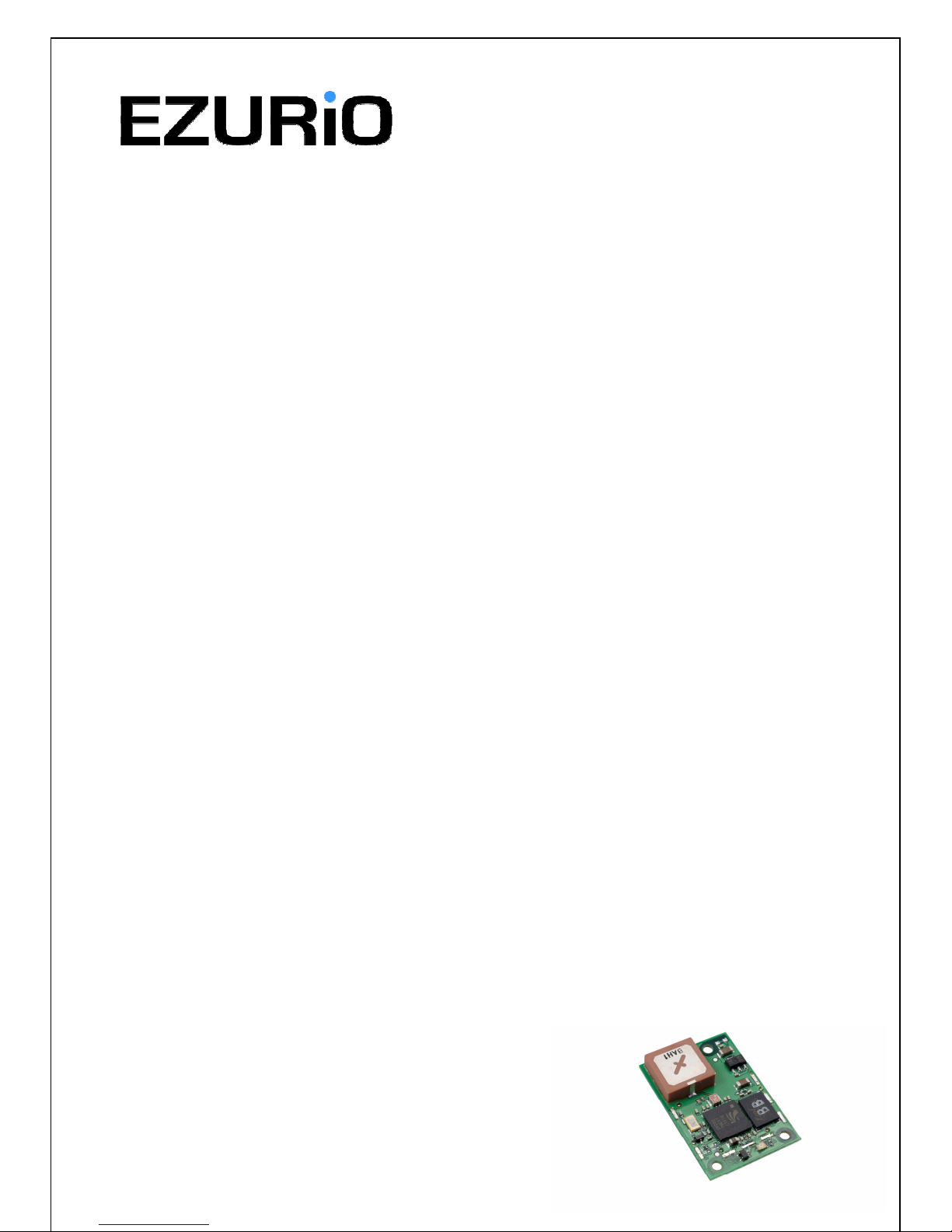
The BISM2 Bluetooth Serial Module is one of the most com act com lete Bluetooth solutions, making
it ideal to integrate into handheld devices. However a version of the BISM2 module is available that
retains the same board size, mounting holes and connector as the revious Bluetooth Module from
Ezurio, allowing users to access the im roved radio erformance and functionality without the need
for any cb modifications.
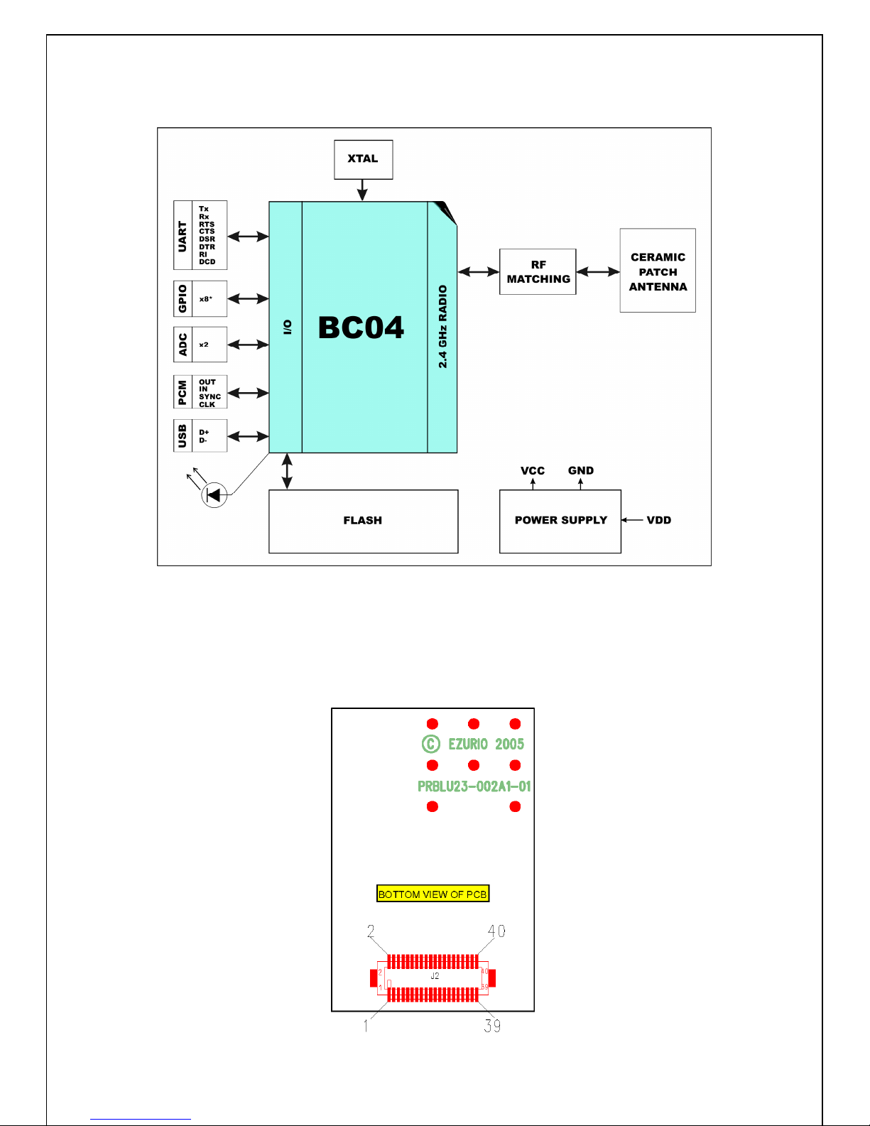
The BISM2 Module is based on Cambridge Silicon Radio’s BlueCore 04 chi set. The module contain
sall of the hardware and firmware for a com lete Bluetooth solution, requiring no further com onents.
The Module has an integrated, high erformance antenna which is matched with the Bluetooth RF and
baseband circuitry. The firmware integrated into the BC04 chi set im lements the higher layer
Bluetooth rotocol stack, u to and including the Generic Access Profile (GAP), Service Discovery
Profile (SDAP), Serial Port Profile (SPP), Dial U Networking Profile (DUN), Headset Profile (HSP),
Hands Free Profile (HFP), File Transfer Profile (FTP) and Audio Gateway. A virtual rocessor is used
within the BC04 to im lement an AT command rocessor. This interfaces to the host system over a
straight forward serial ort using an extensive range of AT commands. The AT command set abstracts
the Bluetooth rotocol from the host a lication, saving many months of rogramming and
integration time. It rovides extremely short integration times for data oriented cable re lacement
and voice a lications. A low cost develo ment system is available for fast roduct evaluation and
develo ment.
An alternative version of firmware is available that rovides rogramming su ort for multi- oint
a lications.
The Module can be configured so that it can be attached to a ‘dumb’ terminal or attached to a PC or
PDA for cable re lacement a lications.
In addition to the Bluetooth functionality, The BISM2 Module rovides access to 9 General I/O lines
and 2 analogue in ut and out ut lines. These can be configured to rovide connection to sim le
devices such as switches or LEDs without requiring any external rocessing. Both the GPIO and ADC
lines can be accessed either via the wired host UART connection, or remotely over the Bluetooth link.
The BISM2 module is su lied in a small form factor cb (22.0mm x 34.0mm x 7.6mm), that
connects to a main cb using a 40 way Hirose connector. The interface is com atible with the BISM1
module. The module includes a high sensitivity, high gain antenna which rovides excellent range.
Ty ical o en field erformance rovides ranges of over 250 metres at transmit owers of 4mW.
Su ort is rovided for low ower modes that make the BISM2 articularly a licable to battery
owered installations.
The BISM2 module is Lead-free and is RoHS com liant and su orts an industrial tem erature range
of -40°C to +85°C.
1.1 Applications
•POS Equi ment
•Medical Equi ment
•Telematics
•Voice A lications
•Industrial Automation
•Automotive A lications
Bluetooth is a trademark owned by Bluetooth SIG, Inc., USA, and is licensed to Ezurio Ltd
Module shown without RF shield

www.ezurio.com
2. Features
Feature Implementation
Bluetooth Transmission Class 1
Fully Bluetooth re-qualified Bluetooth 2.0
Range 250 metres ty ical (free s ace)
Frequency 2.400 – 2.485 GHz
Max Transmit Power +6dBm
Min Transmit Power -27dBm
Receive Sensitivity Better than -86dB
Data Transfer rate U to 300Kb s
Serial Interface RS-232 bi-directional for commands and data using AT commands
Serial arameters Default 9600,n,8,1 - Configurable from 1,200b s to 961,200 b s.
Su ort for DTR, DSR, DCD, RI, RTS, CTS
Physical size 22.8 x 33.8 x 7.6 mm, 8g
24.0 x 69.0 x 7.6mm, 9g (BISM1 Form Factor)
Current consum tion Ty ically 22mA during data transfer in standard ower mode. Lower
owers are attainable with a configurable low ower mode.
Low ower sniff mode 2.5mA ty
Tem erature Range Normal o eration: -40°C to +85°C
Su ly Voltage 3.6V – 7.0V
Brown-out Integrated brown out detection
Interface Levels 3.3V Logic
Audio Audio can be transferred over SCO channels through the PCM interface
at 64kb s. PCM can be configured as master or slave.
Profiles FTP Server, SPP, DUN, FTP, Audio Gateway, Headset, Handsfree
Multi oint Max 7 slaves
Field u gradeable Over UART
Protocols
Single oint firmware is controlled and configured using AT
Commands. Standard multi oint firmware uses a sim le acket based
rotocol and requires a host to enable the module to function
effectively.
Single oint only allows a oint to oint connection whereas multi oint
allows more than one simultaneous connection.
GPIO 9 x digital
2 x analogue (8 bit resolution)
Indicators 1 x rogrammable LED (small form factor board only)
Lead free Lead-free and RoHS com liant

www.ezurio.com
3. Functional Block Diagram
3.1 Connection Diagram
The Module is equi ed with a 40- in 0.5mm itch board-to-board connector that connects to the
a lication latform.

www.ezurio.com
3.2 Pin Descriptions
The Hirose DF12C board-to-board connector on the module is a 40- in double-row rece tacle.
The table below defines the in functions. Note that this in-out is as viewed from the underside of
the Module.
Pin
No.
Signal Description Pin
No.
Signal Description
1 Analogue 0 1.8v Max 2 GPIO1 I/O for Host.
3 Analogue 1 1.8v Max 4 GPIO2 I/O for Host
5 SPI_MISO SPI bus serial O/P 6 UART_RI ‘Ring’ In ut or Out ut
7 SPI_CSB SPI bus chi select I/P 8 UART_DCD In ut or Out ut
9 SPI_CLK SPI bus clock I/P 10 UART_DSR In ut
11 GND 12 GPIO3/UART_DTR
I/O for Host
13 RESET Reset I/P * 14 GPIO4 I/O for Host & LED
15 GND 16 GPIO5 I/O for Host
17 SPI_MOSI SPI bus serial I/P 18 GND
19 UART_CTS Clear to Send I/P 20 PCM_CLK PCM Clock I/P
21 UART_TX Transmit Data O/P 22 PCM_IN PCM Data I/P
23 UART_RTS Request to Send O/P 24 PCM_SYNC PCM Sync I/P
25 UART_RX Receive Data I/P 26 PCM_OUT PCM Data O/P
27 VCC_3V3 3.3V Monitor 28 N/C
29 VCC_5V 3.6V < VIN < 7.0V 30 GND
31 N/C 32 USB / RESERVED Do not connect
33 GPIO6 ** I/O for Host 34 USB / RESERVED Do not connect
35 GPIO7 ** I/O for Host 36 GND
37 GPIO8 ** I/O for Host 38 GND
39 GPIO9 I/O for Host 40 N/C
Notes:
* The reset circuitry within the BISM Serial Modules now incor orates a brown-out detector within
the module. Customers migrating from revious modules should check their im lementation, as they
may be able to sim lify their external ower su ly design. The reset line has a fixed 10kOhm ull
down resistor to ground.
** Pins 33, 35 and 37 were N/C on BISM1. Pin 39 was a 1V8 monitor. Designers migrating between
designs should be aware that these are now available as I/O. Default configuration is as an in ut
PIO lines can be configured through software to be either in uts or out uts with weak or strong ull-
u s or ull-downs. At reset, all PIO lines are configured as in uts with weak ull-downs.
UART_RX, UART_TX, UART_CTS, UART_RTS, UART_RI, UART_DCD and UART_DSR are all 3.3v level
logic. For exam le, when RX and TX are idle they will be sitting at 3.3V. Conversely for handshaking
ins CTS, RTS, RI, DCD, DSR a 0v is treated as an assertion.
Pin 6 (UART_RI) is active low. It is normally 3.3v. When a remote device initiates a connection, this
in goes low. This means that when this in is converted to RS232 voltage levels it will have the
correct voltage level for assertion.

www.ezurio.com
Pin 8 (UART_DCD) is active low. It is normally 3.3v. When a connection is live this in is low. This
means that when this in is converted to RS232 voltage levels it will have the correct voltage level for
assertion.
Pin 10 (UART_DSR) is an in ut, with active low logic. It should be connected to the DTR out ut of the
host. When the BISM2 Module is in high s eed mode (See definition for S Register 507), this in
should be asserted by the host to ensure that the connection is maintained. A deassertion is taken to
mean that the connection should be dro ed, or an online command mode is being requested.
Pin 27 (VCC_3V3 monitor) may only be used for monitoring ur oses. It must not be used as a
current source.
The GPIO ins can be accessed using S Registers 621 to 628. GPIO4 is connected to an LED on the
module. If these I/O ins are set for in ut, then the LED will be driven by the host and a ro riate
drive current requirements must be satisfied. A Logic 1 switches on the LED.
GPIO3 is also used for DTR out ut (active low). See S Register 552 & 553.
Analogue 0 and 1 should not exceed 1.8v and S Registers 701 and 702 are used to access them.
3.3 Electrical Speci ications
3.3.1 Absolute Maximum ratings
Absolute maximum ratings for su ly voltage and voltages on digital and analogue ins of the Module
are listed below; exceeding these values will cause ermanent damage.
Parameter Min Max Unit
Peak current of ower su ly 0 100 mA
Voltage at digital ins -0.3 3.7 V
Voltage at POWER in 3.6 7 V
3.3.2 Recommended Operating Parameters
3.3.2.1 Power Supply
Signal Name Pin No I/O Voltage level Comments
Vcc 29 I 3.6V to 7.0V Ity = 30mA
GND 11, 15, 18,
30, 36, 38
6 Ground terminals to be attached
in arallel
VCC_3V3 27 O 3.3V ty ical For monitoring only. No current
source
3.3.2.2 RS-232 Inter ace
Signal Name Pin No I/O Signal level Comments
UART_TX 21 O VOLmax=0.2V
VOHmin=2.8V
UART_RX 25 I VILmax=0.8V
VIHmin=2.1V
VIHmax=3.7V
UART_CTS 19 I VILmax=0.8V
VIHmin=2.1V
VIHmax=3.7V

www.ezurio.com
UART_RTS 23 O VOLmax=0.2V
VOHmin=2.8V
UART_DSR 10 I VILmax=0.8V
VIHmin=2.1V
VIHmax=3.7V
UART_DTR 12 O VOLmax=0.2V
VOHmin=2.8V
Shared with GPIO3
UART_RI 6 I or O O/P : VOLmax=0.2V
VOHmin=2.8V
I/P : VILmax=0.8V
VIHmin=2.1V
VIHmax=3.7V
Direction may be rogrammed.
UART_DCD 8 I or O O/P : VOLmax=0.2V
VOHmin=2.8V
I/P : VILmax=0.8V
VIHmin=2.1V
VIHmax=3.7V
Direction may be rogrammed.
3.3.2.3 SPI Bus
Signal Name Pin No I/O Signal level Comments
SPI_MOSI 17 I VILmax=0.8V
VIHmin=2.1V
VIHmax=3.7V
Used to re rogram Flash
SPI_MISO 5 O VOLmax=0.2V
VOHmin=2.8V
SPI_CSB 7 I VILmax=0.8V
VIHmin=2.1V
VIHmax=3.7V
SPI_CLK 9 I VILmax=0.8V
VIHmin=2.1V
VIHmax=3.7V

www.ezurio.com
3.3.2.4 PCM Inter ace
Signal Name Pin No I/O Signal level Comments
PCM_CLK 20 I or O O/P : VOLmax=0.2V
VOHmin=2.8V
I/P : VILmax=0.8V
VIHmin=2.1V
VIHmax=3.7V
If unused kee ins o en
PCM_IN 22 I VILmax=0.8V
VIHmin=2.1V
VIHmax=3.7V
PCM_SYNC 24 I or O O/P : VOLmax=0.2V
VOHmin=2.8V
I/P : VILmax=0.8V
VIHmin=2.1V
VIHmax=3.7V
PCM_OUT 26 O VOLmax=0.2V
VOHmin=2.8V
3.3.2.5 General Purpose I/O and ADC
Signal Name Pin No I/O Signal level Comments
GPIO 1 - 9 2,4,12,
14,16,
33, 35,
37, 39
I or O O/P : VOLmax=0.2V
VOHmin=2.8V
I/P : VILmax=0.8V
VIHmin=2.1V
VIHmax=3.7V
AIO_0, AIO_1 1, 3 I Range 0 – 1.8V
3.3.2.6 Miscellaneous
Function Signal Name Pin No I/O Signal level Comments
Reserved USB D- 32 I VILmax =0.3vdd_usb
VIHmin =0.7vdd_usb
Normally inactive.
Pull to GND
through 10K
Reserved USB D+ 34 I VILmax =0.3vdd_usb
VIHmin =0.7vdd_usb
Normally inactive.
Pull to GND
through 10K
Reset RESET 13 I Threshold 2.6V Active HIGH
Terminology:
USB Signal Levels. vdd_usb refers to the internal voltage generated by the LDO regulator on the
module, which is ty ically 3.3V. Hence 0.3vdd_usb and 0.7vdd_usb corres ond to 1.0V to 2.3V. If
Vcc falls below the recommended minimum of 3.6V, these values will be reduced.

www.ezurio.com
4. I/O Characteristics
4.1 Power Consumption
The current drain from the Vcc ower in ut line is de endent on various factors. The three most
significant factors are the voltage level at Vcc, UART Baudrate and the o erating mode.
The hardware s ecification for the Module allows for a voltage range of 3.6 to 7.0 at Vcc. Tests have
shown that there is no significant difference in current draw when Vcc is 5 or 6V. Therefore the data
resented below, ertains to Vcc levels of 3.6 and 5v only. Tests have shown that where ower drain
is an issue, it is best to kee Vcc at the lower end of the range.
The UART baudrate has a bearing on ower drain because as is normal for digital electronics, the
ower requirements increase linearly with increasing clocking frequencies. Hence higher baudrates
result in a higher current drain.
Finally with regards to o erating mode the significant modes are; idle, waiting for a connection,
inquiring, initiating a connection, sniff and connected. With connected mode, it is also relevant to
differentiate between no data being transferred and when data is being transferred at the maximum
rate ossible. The AT command Set document describes how to configure the Module for o timal
ower erformance.
4.1.1 Typical Current Consumption in mA
Baudrate
9,600 38,400 115,200 460,800
3.6v 1.60 1.80 1.96 3.00 Idle Mode, S512=1
5.0v 2.00 2.10 2.30 3.40
3.6v 59.00 59.00 59.00 59.00 Wait for Connection Or Discoverable Mode,
AT+BTP
S508=S510=640, S509=S511=320
5.0v 65.00 65.00 65.00 65.00
3.6v 2.75 2.94 3.10 4.12 Wait for Connection Or Discoverable Mode,
AT+BTP
S508=S510=1000, S509=S511=11*
5.0v 3.26 3.36 3.55 4.63
3.6v 50.00 50.00 50.00 50.00 Inquiring Mode, AT+BTI
5.0v 54.00 54.00 54.00 54.00
3.6v 50.00 50.00 50.00 50.00 Connecting Mode (ATDxxx)
5.0v 54.00 54.00 54.00 54.00
3.6v 6.00 6.10 6.40 7.20 Connected Mode (No Data Transfer)
5.0v 7.20 7.20 7.40 8.20
3.6v 21.50 22.50 24.50 32.50 Connected Mode (Max Data Transfer)
5.0v 24.50 26.00 28.00 36.00
Notes: These figures were obtained with re- roduction firmware. Production values will ty ically be
20% lower.
* Calculated figures

www.ezurio.com
5. DC Characteristics
5.1 RF Per ormance
5.1.1 Transmit Power
Conducted Transmit Power min: 1.0mW (0dBm) max: 4mW (6dBm)
Antenna Gain +2dBi ty .
E ective Transmit Power min:0dBm Max: +6dBm
Out ut ower can be reduced by rogram control
5.1.2 Receive Sensitivity
Receive Sensitivity -86dBm (at 25°C)
Antenna Gain +2dBi ty
E ective Receive Sensitivity -88dBm (at 25°C)
5.1.3 RF Per ormance Data
Receive Sensitivity
-100
-90
-80
-70
-60
-50
-40
-30
-20
-10
0
-40 deg -20 deg 0 deg 20 deg 40 deg 60 deg 80 deg 100 deg
Temperature Deg. C.
Attenuation Setting dBm
NOTE: Measured as attenuation required
to achieve better than 0.1% BER
5.2 Range
See the Data Transfer Rate vs. distance gra h below. The data through ut of the Module is limited to
280Kb s by the arsing of the data being transferred through the RFCOMM stack. The gra h below
shows the ty ical data through ut. Distances are measured in free s ace between 2 Modules.

www.ezurio.com
Data Transfer Rate / Distance
0
100
200
300
400
500
600
700
800
10m 50m 100m 150m 200m 250m 300m
Distance (meters)
Data Transfer Rate (kbps)
RF data rate
Serial port data rate
5.3 Temperature Per ormance
Data Transmit Rate with Temperature and Attenuation
0
100
200
300
400
500
600
700
800
-60dBm -65dBm -70dBm -75dBm -80dBm -85dBm -90dBm
dBm attenuation
Data Transmission Rate kbs
-40 deg
-20 deg
0 deg
20 deg
40 deg
60 deg
80 deg
100 deg

www.ezurio.com
Serial Module
UART Interface
UART_TX
UART_RX
UART_CTS
UART_RTS
UART_DSR
UART_DTR
UART_RI
UART_DCD
/RXD
/TXD
/RTS
/CTS
/DTR
/DSR
/RING
/DCD
RS232 Interface
6. Functional Description
The BISM2 Bluetooth module is a self-contained Bluetooth roduct and requires only ower to
im lement full Bluetooth communication. The integrated, high erformance antenna together with the
RF and Base-band circuitry rovides the Bluetooth wireless link and the UART interface rovides a
connection to the host system.
The variety of interfaces and the AT command set allow the BISM2 module to be used for a wide
number of short range wireless a lications, from sim le cable re lacement to com lex multi oint
a lications, where multi le radio links are active at the same time.
The com lexity and flexibility of configuration are made sim le for the design engineer by the
integration of a extremely com rehensive set of AT commands, su lemented with a range of “S”
registers which are used for non-volatile storage of system arameters. These are fully documented
in the “Blu2i AT Command Reference Manual”.
To rovide the widest sco e for integration a range of different hysical host interfaces are rovided:
6.1 Inter aces
6.1.1 UART inter ace
UART_TX, UART_RX, UART_RTS and UART_CTS form a conventional asynchronous serial data ort
with handshaking. The interface is designed to o erate correctly when connected to other UART
devices such as the 16550A. The signalling levels are nominal 0V and 3.3V and are inverted with
res ect to the signalling on an RS232 cable. The interface is rogrammable over a variety of bit
rates; no, even or odd arity; sto bit and hardware flow control. The default condition on ower-u
is re-assigned in the external Flash. Two-way hardware flow control is im lemented by UART_RTS
and UART_CTS. UART_RTS is an out ut and is active low. UART_CTS is an in ut and is active low.
These signals o erate according to normal industry convention.
By writing different values to the relevant S register the UART_RI can be continuously olled to detect
incoming communication. The UART_RI signal serves to indicate incoming calls.
UART_DSR is an active low in ut. It should be connected to DTR out ut of the host. When the module
is running in high s eed mode (See definition for S Reg 507), this in should be asserted by the host
to ensure connection is maintained. A de-assertion is taken to mean that the connection should be
dro ed, or an online command mode is being requested.
The module communicates with the customer a lication using the following signals:
RS-232
Port /TXD @ a lication sends data to the module’s UART_RX signal line
Port /RXD @ a lication receives data from the module’s UART_TX signal line
Figure 6.1 : UART interfaces
Note that the serial module out ut is at 3.3V CMOS logic levels. Level conversion must be added to
interface with an RS-232 level com liant interface.
A lication

www.ezurio.com
6.1.2 SPI bus
The Module is a slave device that uses terminals SPI_MOSI, SPI_MISO, SPI_CLK and SPI_CSB. This
interface is used for rogram firmware u dates at the factory.
Ezurio su ly a PC based utility to allow firmware u grade over the UART ort. It is highly
recommended that customers should use this method for u dating firmware.
Note: The designer should be aware that no security rotection is built into the hardware or firmware
associated with this ort, so the terminals should not be ermanently connected in a PC a lication.
6.1.3 GPIO Port
Eight lines of rogrammable bi-directional in ut/out uts (I/O) are rovided that can be accessed
either via the UART ort, or Over The Air (OTA) from a second Bluetooth unit. These can be used as
data in uts or to control external equi ment. By using these in OTA mode, a BISM module can be
used for control and data acquisition without the need for any additional host rocessor.
Each of the GPIO[1:8] orts can be inde endently configured to be either an In ut or Out ut. A
selection of orts can be accessed synchronously.
GPIO 1 and 2 can be configured as event counters.
The orts are owered from VCC. The mode of these lines can be configured and the lines are
accessed via S Registers 621 to 628.
Low latency I/O can be accessed by using Ezurio’s I/O via an enhanced inquiry rocess.
6.1.4 PCM CODEC Inter ace
PCM_OUT, PCM_IN, PCM_CLK and PCM_SYNC carry u to three bi-directional channels of voice data,
each at 8ksam les/s. The format of the PCM sam les can be 8-bit A-law, 8-bit µ-law, 13-bit linear or
16-bit linear. The PCM_CLK and PCM_SYNC terminals can be configured as in uts or out uts,
de ending on whether the module is the Master or Slave of the PCM interface. Please contact an
Ezurio FAE for further details.
The Module is com atible with the Motorola SSI TM interface and interfaces directly to PCM audio
devices including the following:
6.1.4.1 Compatible Codec Chips
•Winbond W61360 13-bit linear CODEC (Motorola MC145483 com atible)
•OKI MSM7702 single channel A-law and µ-law CODEC
•OKI MSM7705 four channel A-law and µ-law CODEC
The default codec su ort is for the Winbond W61360
Codec development boards that mate with the EZURiO Wireless Developers Kit are available for each
of the three codecs listed above.
6.1.5 ADC
The BISM2 rovides access to two 8-bit ADCs. These rovide an in ut range of 0mV to 1,800mV,
which can be read using the S registers 701 and 702.
Suitable external scaling and over-voltage rotection should be incor orated in your design. The
module rovides 5 sam les er second at the UART with a baud rate of 115200 or above.
Low latency access of the u er 6 bits of the ADCs can be obtained by using Ezurio’s I/O via an
enhanced inquiry rocess.
6.1.6 LED
A single LED rovides information on the status of the module. It is controlled by a S register to
dis lay the status of various arameters and is useful for debug and test.

www.ezurio.com
7. Integrated Firmware
7.1 General
The BISM2 has been designed to rovide the fastest route to market for designers who wish to use
Bluetooth to wirelessly enable their roducts. To achieve this Ezurio has im lemented a wide ranging
set of AT commands that control all of the standard Bluetooth tasks. These remove the com lexity of
Bluetooth from the design engineer and allow the wireless link to be controlled by means of a sim le
set of commands.
For a lications where multi le concurrent live connections need to be maintained a variant of
firmware is available which is s ecifically targeted at multi oint o eration.
For both a lications a com rehensive range of windows based software is available to s eed u the
design rocess. A low cost develo ment kit is also available that can be used for rototy ing both
cable re lacement and multi oint a lications.
7.2 Pro iles
Bluetooth has been designed to accommodate a very wide range of wireless a lications. To enable
these different a lications the Bluetooth SIG (S ecial Interest Grou ) has defined a series of
different rofiles that define the way in which Bluetooth devices communicate with each other and
erform basic functions. These rovide a base line of intero erability for s ecific a lication
scenarios, u on which more com lex user a lications can be develo ed.
There are over 30 different rofiles, many of which have been develo ed for s ecific a lications.
The BISM2 firmware is rovided with su ort for the rofiles that are most commonly required for
cable re lacement a lications.
The current rofiles su ort includes:
•GAP Generic Access Profile. The base connection rofile u on which others are based.
•SDP Service Discovery Profile. The rofile to find other Bluetooth devices and the services
they su ort.
•SPP Serial Port Profile. Emulation of a serial cable for cable re lacement a lications.
•DUN Dial U Networking. Profile su ort for connection to an external PSTN, GSM, GPRS
or VPN connection.
•Audio Gateway. The base element for Headset and Handsfree rofile. A ortion of these
rofiles must be im lemented within the host system.
•HSP Headset Profile. Su orts early im lementations of headsets. Now largely re laced
by the:
•HFP Hands-free rofile, which rovide more control over the headset o eration.
•FTP File Transfer Profile (full client su ort).
7.3 AT Overview
The AT command set is well known by engineers and was develo ed to aid the integration of PSTN
modems. It rovides sim le high level commands for com lex functions that can easily be
incor orated into rograms or used within rogramming scri ts.
Ezurio has used this familiar conce t and extended it to Bluetooth to sim lify the integration of
Bluetooth for roduct designers. Rather than having to understand the many stages of setting u a
Bluetooth connection or function, a single AT command is all that is required.
For exam le to connect to a Bluetooth device with an address 00809844EA13, all that is needed is to
send the string

www.ezurio.com
ATD00809844EA13
to the UART of the BISM2 module. The module will attem t to make a connection and return connect
00809844ea13,1101) or (NO CARRIER), de ending on whether the connection was successful.
The sco e of the AT command set develo ed by Ezurio is such that most Bluetooth functionality can
be covered, greatly reducing develo ment time.
To rovide additional functionality a range of “S” registers has been im lemented. These allow
rogram settings to be stored to control the BISM2 function and also give access to configuring and
reading orts and status registers within the BISM2.
Full details of the AT command set are rovided in the Blu2i AT Command Reference Manual.
7.3.1 AT eatures at a glance
7.3.1.1 General
•Configure two modules to automatically connect and transfer data, audio or a combination of
data and audio when both devices are owered. The eer device does not have to be another
Intelligent Serial Module. It is ossible to im lement auto connect with a Bluetooth enabled
mobile hone.
•Automatically re-connect devices when a connection is dro ed.
•Remotely access the AT arser of the remote unit from a master device to erform Over The
Air (OTA) configuration.
•Configure the module to enter a state on ower u and after a eriod of time change to
another state automatically. This allows units to be laced in the discoverable state for a
limited time eriod.
•Read and write to GPIO lines
•Read the ADC channels
•Get fast GPIO and ADC status through an inquiry res onse ( atent ending)
7.3.1.2 Audio
•Set u audio connections
•Enable / disable Auto Answer for incoming connections
7.3.1.3 UART
•Change the baud rate from 1200 to 921,600 baud.
•Use the DSR line to dro connections
•Flexible configuration as either DTE or DCE
•Change esca e sequence character
•Change the number of Sto bits and Parity
•Enable or disable echoes
7.3.1.4 Security
•Enable Authentication by requiring a PIN code for incoming AND / OR outgoing connections
•Enable data to be encry ted over the air for incoming AND / OR outgoing connections. The
module can be configured to be:
non-connectable and non-discoverable,
non-connectable but discoverable,
connectable but non-discoverable,
connectable and discoverable.
•Automatically store Paired devices in a trusted device database in the flash memory

www.ezurio.com
7.3.1.5 Bluetooth
•Set the module to be a master or slave
•Make a Bluetooth connection to a s ecified device
•Perform a full inquiry for other Bluetooth devices
•Query a remote device to check if a service is offered
•Fetch the friendly name of a remote device
•Increase or decrease the delay before the master abandons a connection attem t
•Change the device class code
•Set the device’s friendly name
•Change the Inquiry scan time
•Change number of returned devices from an inquiry scan
•Obtain the RSSI value for a connection
7.3.1.6 Power Management
•Decrease or increase the out ut ower to suit your connection range
•Configure the modules to work in Sniff and other low ower modes.
7.4 Multipoint Firmware
For multi oint o eration, the same hardware can be loaded with multi oint software. Whereas the
firmware for single oint ‘AT’ communication only allows one connection to be active at any one time,
using multi oint firmware allows a number of simultaneous connections to be made and maintained.
It also allows connections to multi le rofiles to one or more devices. Multi oint firmware should be
seen as a conce t of channels instead of slave connections.
When o erating in Bluetooth multi oint mode, the resources and bandwidth of a Bluetooth master
device are shared amongst the different connected devices. This has an im act on the maximum
through ut to any one device. If multi le device connections are maintained it also im acts on the
memory resources and device database within the Bluetooth stack. Designers should be aware of
these restrictions when using multi oint configurations. In most cases better latency and ower
consum tion can be achieved by olling or fast data transfer rather than by maintaining concurrent
connections.
In general, multi oint connections are viable for u to three connections, but other connection
schemes become a ro riate if a greater number of devices are being de loyed.
7.5 OTA (Over the Air) Con iguration
When the BISM2 has its remote AT arser enabled, its settings can be remotely controlled by a
master unit (see register S536). This laces the slave unit’s AT arser in remote mode roviding
over the air configuration. This mode is of use for remote sensor a lications, where no host
rocessor is required to control the slave Bluetooth unit.
7.6 Boot modes
The module has the ca ability of booting into 1 of 7 modes. Currently only Boot Mode 1 is su orted.
Boot Mode 1 is default and gives functionality equivalent to the BISM1 module.
These modes will s ecify different PSKEY settings to allow for different basic o eration. Please
contact Ezurio for further information.

www.ezurio.com
8. Low Power Modes
The current drain from the Vcc ower in ut line is de endent on various factors. The three most
significant factors are the voltage level at Vcc, UART baud rate and the o erating mode.
The hardware s ecification for the blu2i module allows for a voltage range of 3.6 to 7.0v at Vcc. Tests
have shown that there is no significant difference in current draw when Vcc is 5 or 6V.
The UART baud rate has a bearing on ower drain because as is normal for digital electronics, the
ower requirements increase linearly with increasing clocking frequencies. Hence higher baud rates
result in a higher current drain.
Finally with regards to o erating mode the significant modes are; idle, waiting for a connection,
inquiring, initiating a connection and connected. With connected mode, it is also relevant to
differentiate between no data being transferred and when data is being transferred at the maximum
rate ossible.
The o erating mode can best be described by stating the AT commands required to enter that mode.
In addition, there are certain S Registers which have a direct im act on ower consum tion, which
are described next.
The blu2i Module has a single LED which can be configured to dis lay connection status. Tests have
shown that this LED can consume u to 5.3mA which is more than double the current draw when in
Idle mode. S Register 534 can be used to com letely disable this indicator.
S Registers 508 to 511, which s ecify the age and inquiry scan intervals and windows, can be used
to adjust the average current drain when in discoverable and or connectable modes. Registers 508
and 509 s ecify the interval and window for age scans and registers 510 and 511 s ecify the
interval and window for inquiry scans. Register airs 508/509 and 510/511 describe duty cycles when
the blu2i module goes into scan modes. It is while scanning that the highest current draw occurs. The
average current draw is determined by sim le arithmetic using the values stored in the 508/509 and
510/511 register airs.
Ty ical current consum tion is given in Section 4.1.
The current drain while waiting for a connection or discoverable mode is about 30 times higher than
in idle mode. This is when the age/inquiry scan duty cycle is 100%. These modes give the quickest
res onse to a age or inquiry request from a remote eer.
It is ossible to reduce the duty cycle down to as low as 0.5% at the ex ense of res onse time. The
res onse time can be s ecified via S Registers 508 and 510 for age and inquiry res ectively, where
the worst case res onse time can be as high as 2.5 seconds. Then the duty cycle can be varied by
changing the value of S Registers 509 and 511 a ro riately.
For exam le, if S Register 508 and 510 are both set to 1000ms and S Register 509 and 511 are both
set to 11ms then the duty cycle is reduced to 1%, this means that average current drain at 5.0v will
be 2% of 65mA lus the normal idle mode current, that is, it is as low as 2.75mA. However, in this
case, it can take u to 1 second to establish a connection.
The connected state current consum tion while a master or slave can be considerably reduced by
enabling Sniff mode, described in detail in the next section.
8.1 Low Power Modes using Sni
Bluetooth connections are master/slave in nature. A master sends ackets and a slave has to
acknowledge that acket in the next timeslot. Timeslots in Bluetooth are 625 microseconds wide. This
im lies that a master will always know when ackets will be sent and received, which further means it
is able to o timise ower usage by switching on ower hungry circuitry only when needed.
mA
3.6V 3.20 Current er LED (when fitted)
5.0V 5.30

www.ezurio.com
A slave on the other hand does NOT have rior knowledge of when a acket will be received and has
to assume that a acket will be received from a master on every receive slot. This means that it has
to leave its receiving circuitry on for most of the receive slot duration. The result of this is high ower
consum tion as illustrated in the ower table in Section 4.1, where a slave with no data transmission
still consumes around 31mA whereas a master consumes only 6mA.
This roblem was identified very early in the evolution of Bluetooth (es ecially since headsets s end
all their time as a slave in a Bluetooth connection) and it was solved by having a mode called Sniff,
with a ro riate lower layer negotiating rotocol.
Sniff mode during connection is basically an agreement between the slave and its master that data
ackets will only be exchanged for N timeslots every M slots. The slave can then assume that it will
never be contacted during N-M slots, and so can switch its ower hungry circuitry off. The
s ecification goes further by also s ecifying a third arameter called ‘timeout’ (T) which s ecifies
‘extra’ timeslots that the slave will agree to listen for after receiving a valid data acket. Put another
way, if a data acket is received by the slave, then it knows that it MUST carry on listening for at
least T more slots. If within that T slot time eriod another data acket is received, then the timer is
restarted. This mechanism ensures low ower consum tion when there is no data transfer – at the
ex ense of latency. When there is a lot of data to be transferred, it acts as if sniff mode were not
enabled.
It is stated above that during sniff mode, a slave listens for N slots every M slots. The Bluetooth
s ecification states that a master can have u to 7 slaves attached to it with all slaves having
requested varying sniff arameters. It may therefore be im ossible to guarantee that each slave gets
the M arameter it requested. In light of this, the rotocol for enabling sniff mode s ecifies that a
requesting eer s ecify the M arameter as a minimum and maximum value. This will allow the
master to interleave the sniff modes for all slaves attached.
For this reason, the sniff arameters are s ecified in the BISM2 module via four S registers. S
Register 561 is used to s ecify ‘N’, S Register 562 is used to s ecify ‘T’ and S Registers 563/564 are
used to s ecify minimum ‘M’ and maximum ‘M’ res ectively. Although the s ecification defines these
arameters in terms of timeslots, the S register values have to be s ecified in units of milliseconds
and the firmware does the necessary translation to timeslots.
Data Exhange
High Power Consumption
Low Power Consumption
M
Slots (Negotiated)
M
Slots (Negotiated)
N
Slots
N
Slots
N
Slots
T
Slots
T
Slots
T
Slots
T
Slots
T
Slots
Data Exchange
Data Exchange
Data Exchange
Data Exchange
Data Exchange

www.ezurio.com
9. Application Examples
9.1 RS232 Modem Signals
Just as a tele hony modem has control and status lines, the blu2i Module also rovides for 6 control
and status lines as er the table below. The direction column is as seen from the module’s view oint.
Direction Function
IN or OUT * CI also known as RI (Ring Indicate)
IN or OUT * DCD (Data Carrier Detect)
IN DSR (Data Set ready)
OUT DTR (Data Terminal Ready)
IN CTS (Clear to Send)
OUT RTS (Request to Send)
* configurable with S register 552
The first four lines are under rogram control. These use four of the GPIO ins and are ma ed to
I/O as er the table below. The last two are under control of the UART driver and their functionality is
always enabled.
Direction Connector Pin Label Function
IN/OUT GPIO1 General Pur ose I/O
IN/OUT GPIO2 General Pur ose I/O
IN/OUT UART_RI In ut/Out ut from module
IN/OUT UART_DCD In ut/Out ut from module
IN UART_DSR In ut to Module
IN/OUT GPIO3/UART_DTR General Pur ose I/O (or DTR functionality)
IN/OUT GPIO4/LED General Pur ose I/O (LED)
IN/OUT GPIO5 General Pur ose I/O
IN/OUT GPIO6 General Pur ose I/O
IN/OUT GPIO7 General Pur ose I/O
IN/OUT GPIO8 General Pur ose I/O
Notes:
1. PIO4 (DSR) is used by the blu2i module to sense that the host is connected, and is intricately
linked with connections. For outgoing calls, if this line is not asserted then an error is indicated.
Similarly for AT+BTP and AT+BTG.
While in a call, for a ro riate modes, a de-assertion means fall into command state. If the de-
assertion exists for longer than the eriod s ecified in S Register 519 then the connection is dro ed
as if an ATH command was received.
2. PIO2 (RI), is normally de-asserted. When an incoming connection is detected it will be
asserted, until the connection is either answered or rejected using ATA and ATH res ectively. See S
Registers 552 & 553 for more details

www.ezurio.com
3. PIO3 (DCD) will be de-asserted when the device is in the unconnected state. Asserted when a
connection is active. See S Registers 552 and 553 for more details.
4. PIO5 is either used as GPIO or driven as UART_DTR. When the unit is configured in ure host
mode, this in is forced into UART_DTR and is asserted when there is a Bluetooth connection.
GPIO Pins 1 to 8 are available for general ur ose use.
9.2 Modem signalling over Bluetooth
The RFCOMM rotocol used in Bluetooth for im lementing the serial ort rofile allows for the
exchange of four modem signals. This information is contained in a s ecial trans arent message
which contains bits identified as RTR, RTC, DV and IC which de ending on the ty e of serial device
being emulated ma s to DTR or DSR, RTS, DCD and RI res ectively. In addition, this message also
includes the ability to convey a BREAK in ut from one end to the other.
To allow for the greatest flexibility and variability in how the modem control signals are used out in
the real world, S Registers 551, 552 and 553 have been rovided which allow for any of RTR,RTC,DV
and IC to be ma ed to any modem control/status line.
BREAK signal on RX line
If the host sends a break signal of duration greater than 100ms, then the blu2i module is
configured to treat that as a signal to erform a hardware reset.
This being the case it is not ossible to convey a BREAK over Bluetooth to the eer device.
Reset
The module can be reset by the host without the need of any I/O using a BREAK signal. The
module has been configured to reset when the RX line detects a break condition for durations
greater than 100 milliseconds.
The Reset line has a fixed ull down resistor of 10kOhm
9.3 Pure Cable Replacement Mode
The module has the ca ability of being reset into a ure 5-wire data cable re lacement mode. The 5
wires being RX, TX, CTS, RTS and GND. This mode requires no changes to a host a lication since the
Bluetooth connection is automatically set u on ower u . If the connection is lost the BISM2 module
will constantly retry until the connection is reinstated.
By im lication, two devices are needed to re lace a cable. One device is re-configured to always be
a master and the other, a slave.
Assuming the Bluetooth address of the master to be <bdaddr_m> and that of the slave to be
<bdaddr_s>, the master module is configured by sending it the following AT commands:
AT&F*
ATS512=1
ATS504=1
ATS507=2
ATS530=2000
AT&W
AT+BTR<bdaddr_s>
The ATS507=2 setting uts the device in DSR dro mode only. This means that when the device
needs to be reconfigured, deasserting the DSR line will ensure that the module res onds quickly to AT

www.ezurio.com
commands. This further means that in stand alone mode, the DSR in ut line MUST be asserted e.g.
0V in TTL signal mode.
The slave is configured by:
AT&F*
ATS512=4
ATS0=-1
AT&W
AT+BTR<bdaddr_m>
Where <bdaddr_m> is o tional. If it is not s ecified, then the slave unit will acce t connections from
any device. If s ecified then only connections from the device s ecified will be acce ted.
If it is desired that the slave unit should not be discoverable (the master is by default not
discoverable), then the configuration commands are:
AT&F*
ATS512=3
ATS0=-1
AT&W
AT+BTR<bdaddr_m>
Where <bdaddr_m> is o tional. If it is not s ecified, then the slave unit will acce t connections from
any device. If s ecified then only connections from the device s ecified will be acce ted.
When the units are next ower cycled, the slave unit will wait for the master to connect to it and the
master will continually look for the slave. If a connection attem t fails, the master will wait for 2
seconds before reattem ting a connection. This 2 second delay can be varied by issuing it an ATS530
command with an a ro riate value in the range 100ms to 15000ms.
IMPORTANT NOTE: The DSR in ut to the module MUST be asserted for the auto connection to
succeed. When o erating at TTL levels a 0V is seen as an assert state. When o erating at RS232
levels and voltage greater than 3V is seen as assert. It is usual to connect the DTR line of the host to
the DSR line of this device.
9.4 Audio Cable (voice)
With a air of these modules it is ossible to re lace a mono audio cable with two way traffic. That is,
a setu where a micro hone is connected to a s eaker at the remote end and vice versa. So this
mode effectively re laces two audio cables.
Assuming the Bluetooth address of the master to be <bdaddr_m> and that of the slave to be
<bdaddr_s>, the master module is configured by sending it the following AT commands:
AT&F*
ATS512=1
ATS504=1
ATS530=2000
ATS532=7
AT&W
AT+BTR<bdaddr_s>
And the slave is configured by:
AT&F*
ATS512=4
ATS0=-1
Table of contents