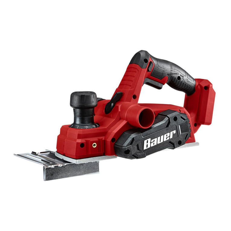
F.F. Group P 720 PLUS User manual

P 720 PLUS
ORIGINAL INSTRUCTIONS
NOTICE ORIGINALE
ISTRUZIONI ORIGINALI
ORIGINALNO UPUTSTVO ZA RAD
EN
IT
EL
SR
RO
BG

1
2
8
9
7
2
12
11
13
14
15
10
5
6
P 720 PLUS
EN
A
IT
EL
SR
RO
BG
PLANER..............................................................................................................................................................05
RABOT.......................................................................................................................................................09
PIALLA..........................................................................................................................................................................13
STRUG.....................................................................................................................................................................23

2
3
8
4
7
www.ffgroup-tools.com
3
11
14
8
4
3
10
9
15
15a
P 720 PLUS
B
C

4
18
21
23
22
17
16
18 2019
12
E
P 720W PLUS
D
G

English | 5
www.ffgroup-tools.com
P 720 PLUS
www.ffgroup-tools.com
Read all safety warnings and all instructions. Failure
to follow the warnings and instructions may result
warnings and instructions for future reference. The
term “power tool” in the warnings refers to your
mains-operated (corded) power tool or battery-op-
erated (cordless) power tool.
WORK AREA
Keep work area clean and well lit. Cluttered or dark
-
-
uids, gases or dust. Power tools create sparks which
may ignite the dust or fumes.
Keep children and bystanders away while operating
a power tool. Distractions can cause you to lose con-
trol.
-
ify the plug in any way. Do not use any adapter plugs
plugs and matching outlets will reduce risk of elec-
tric shock.
-
faces, such as pipes, radiators, ranges and refriger-
ators. There is an increased risk of electric shock if
your body is earthed or grounded.
Do not expose power tools to rain or wet conditions.
Water entering a power tool will increase the risk of
electric shock.
-
ing, pulling or unplugging the power tool. Keep cord
Damaged or entangled cords increase the risk of
electric shock.
When operating a power tool outdoors, use an ex-
tension cord suitable for outdoor use. Use of a cord
suitable for outdoor use reduces the risk of electric
shock.
If operating a power tool in a damp location is un-
protected supply. Use of an RCD reduces the risk of
electric shock.
Stay alert, watch what you are doing and use com-
mon sense when operating a power tool. Do not use
-
ence of drugs, alcohol or medication. A moment of
inattention while operating power tools may result
mask, non-skid safety shoes, hard hat, or hearing pro-
tection used for appropriate conditions will reduce
ENGLISH
the power tool on. A wrench or a key left attached to
a rotating part of the power tool may result in per-
at all times. This enables better control of the power
tool in unexpected situations.
-
extraction and collection facilities, ensure these are
connected and properly used. Use of dust collection
can reduce dust-related hazards.
POWER TOOL USE AND CARE
Do not force the power tool. Use the correct pow-
er tool for your application. The correct power tool
it was designed.
Do not use the power tool if the switch does not
controlled with the switch is dangerous and must
be repaired.
or the battery pack from the power tool before
-
sures reduce the risk of starting the power tool
accidentally.
Store idle power tools out of the reach of children
and do not allow persons unfamiliar with the power
tool or these instructions to operate the power tool.
Power tools are dangerous in the hands of untrained
users.
Maintain power tools. Check for misalignment or
-
before use. Many accidents are caused by poorly
maintained power tools.
Keep cutting tools sharp and clean. Properly main-
tained cutting tools with sharp cutting edges are
less likely to bind and are easier to control.
Use the power tool, accessories and tool bits etc.
in accordance with these instructions, taking into
account the working conditions and the work to be
performed. Use of the power tool for operations
-
ardous situation.
SERVICE
person using only identical replacement parts. This
will ensure that the safety of the power tool is main-
tained.
ERS
Wait for the cutter to stop before setting the tool
down. An exposed rotating cutter may engage the

| English6P 720 PLUS
surface leading to possible loss of control and se-
Hold the power tool by insulated gripping surfaces
only, because the cutter may contact its own cord.
an electric shock.
Use clamps or another practical way to secure
and support the workpiece to a stable platform.
Holding the work by your hand or against the body
Make sure the power supply information on the ma-
chine's rating plate are compatible with the power
supply you intend to connect it to.
This appliance is Class II* and is designed for connec-
tion to a power supply matching that detailed on the
compatible lead rated for this appliance. Follow all
the instruction supplied with the extension lead.
*Double insulated
earth connection as supplementary insulation is
applied to the basic insulation to protect against
insulation.
Make sure your extension cord is in good condition.
When using an extension cord, be sure to use one
draw. An undersized cord will cause a drop in line
-
Use a separate electrical circuit for your tools. This
circuit should be protected with the appropriate
time-delayed fuse. Before connecting the motor to
the power line, make sure the switch is in the OFF
-
PRODUCT
INTENDED USE
This tool is intended for planing wooden materi-
als such as beams and boards; it is also suitable for
chamfering edges and rabbeting.
TECHNICAL DATA
Article number 41523
P 720 PLUS
Power W 720
No-load speed min-1 16000
Max planing width mm 82
Planing depth mm 0-2
Rebating depth mm 18
Weight kg 3,2
EN 60745-1
dB(A) 86
dB(A) 97
Uncertainty K dB 3
h
60745-1
ah24,7
K21,5
1. Handle
2. Ventilated motor housing
3. Rebating depth guide
4.
5. Trigger lock button
6. Power trigger
7.
8.
9. Parallel guide locking knob
10. Soleplate
11. Power indicator, lights when planer is energized
12. Blade tool holder
13.
14.
15. Parallel guide
16. Blade
17. Drum plate
18. Clamping screw
19. Set plate
20. Set screw
21. Blade drum
22. Parking rest
23. Springloaded guard
24. Dust bag
OPERATION INSTRUCTIONS
cutting depth or cutting width.
Make sure that the workpiece is securely fas-
tened to the work bench and that the work bench
Lower the parking rest on the rear of the
planer when you stop work. It protects the blade
when it is not in use .
to the desired
depth. Plug the planer into the wall socket. Hold in the

English | 7
www.ffgroup-tools.com
P 720 PLUS
trigger lock button and then pull the power trigger
.
cut. Always return the planing depth to 0 when you
beginning your next planing task.
Attach the parallel guide and fasten it using
the locking knob.
ADJUSTING THE REBATING DEPTH
Set the rebating depth guide to the desired
.
ADJUSTING THE REBATING WIDTH
guide. Loosen the wing nut , set the parallel
guide to the desired position and then tighten the
wing nut again.
makes it possible to chamfer the edges of the
workpiece.
WORK PROCEDURE
CHANGING BLADES
Always unplug the mains lead from the
they might be too blunt to produce a clean cut and
if necessary.
The tungsten carbide tipped blades are dou-
edge used once one of the edges is worn.
in the blade tool holder .
The cutting depth of the blade seldom needs to be
until you
1. Undo the three clamping screws , hold
down the springloaded guard and slide
the blade out of the set plate . You can
also choose to slide the entire blade holder out
of the blade drum
blade when the blade holder is loose.
and
pay attention to how the parts are assembled.
1.
easily disassemble. Make sure that all the parts
are in the right place when the blade holder is
put back.
BLADES
1. -
er.
2. Make sure that the slot in the blade lines up
-
the drum plate that must line up with two holes
3. Place the assembled blade holder into the blade
drum. Make sure that the blade holder is in the
centre of the blade drum.
4. Tighten the three clamping screws. Turn the
blade drum by hand to make sure that it can ro-
tate freely before switching the planer on.
of the blade must not protrude more than 1.1 mm
blades, make sure that all the screws are tight.
Select desired chip outlet side (left or right) with
. An extraction
hose (Ø 35 mm), can be attached on either side of
If desired, attach the dust bag by sliding the noz-
zle onto the appropriate chip extraction port. For
through the bag.
You can also connect your tool to a suitable dust ex-
traction system through the extraction port. Hose
adaptors (not included) may be needed depending
on the side of your dust hose.
-
traction port when cutting damp wood. Clean
cutter has stopped running and the tool has been
unplugged from the power source.
Always unplug the mains lead from the
1. -
both belt pulleys.
2.
3.
the large pulley while rotating the pulley by
hand.
4. Make sure that the belt sits properly in the
5.

| English8P 720 PLUS
TROUBLESHOOTING GUIDE
• Make sure that
the mains lead is
undamaged and
properly connected
to the wall socket.
• Check that the wall
Poor performance.
• Refer to the Chang-
ing blades section
• Check that the
holes in the motor
(2) are free from
debris.
The planer switches on
rotate.
•
the Changing the
Regular inspection and cleaning reduces the neces-
sity for maintenance operations and will keep your
tool in good working condition. The motor must be
Recycle raw materials instead of disposing
as waste. Machine, accessories and pack-
friendly recycling. The plastic components
are labeled for categorized recycling.
Double insulation
For indoor use only. Do not expose to
rain.
Wear eye protection.
is not worn.
protection is not worn.
read and understand this manual before
using this product.
Important!
GUARANTEE
This product is warranted in accordance with the le-
-
handling will be excluded from the guarantee. In
case of a claim, please send the machine, completely
electric power tools.
We declare under our sole responsibility that this
product is in conformity with the following stan-
19300, Aspropyrgos - Greece

Français | 9
www.ffgroup-tools.com
P 720 PLUS
accidents.
-
des outils à branchement de terre. Des fiches non
-
Ne pas exposer les outils à la pluie ou à des condi-
-
-
-
-
-
des personnes.
-
ramasser ou de le porter. Porter les outils en ayant le
-
cidents.
-
personnes.
-
tendues.
-
Si des dispositifs sont fournis pour le raccordement
-
-
-
construit.
-
-
enfants et ne pas permettre à des personnes ne
de le faire fonctionner. Les outils sont dangereux
De nombreux accidents sont dus à des outils mal en-
tretenus.

| Français10 P 720 PLUS
-
-
dangereuses.
-
est maintenue.
RABOTS
-
-
-
-
*Double isolation -
-
bois, notamment les poutres et les planches ; il peut
feuillures.
Art N° 41523
P 720 PLUS
Tension nominale
Alimentation W 720
min-1 16000
Largeur maximale de
rabotage mm 82
Profondeur de rabo-
tage mm 0-2
Profondeur des
feuillures mm 18
Poids kg 3,2
dB(A) 86
dB(A) 97
Incertitude K dB 3
h-
ah24,7
K21,5
1.
2.
3. Guide de profondeur des feuillures
4.
feuillures
5.
6.
7.

Français | 11
www.ffgroup-tools.com
P 720 PLUS
8.
graduation
9.
10. Semelle
11.
12. Porte-outil de lame
13. Capot de courroie de transmission
14.
15.
16. Lame
17.
18. Vis de serrage
19.
20.
21. Tambour de lame
22. Pied
23. Protection à ressort
24. Sac à poussière
profondeur ou la largeur de coupe.
et ne bouge pas.
Abaissez le pied -
.
rabotage -
, puis
.
-
.
Mettez le guide de profondeur de refeuillement
,
permettent de chanfreiner les bords de la pièce.
-
-
PETITES PIÈCES
-
-
-
-
-
lièrement les lames, et les retourner ou les changer
Les lames en carbure de tungstène sont à double
.
La profondeur de coupe de la lame doit rarement
1. , mainte-
nir la protection à ressort (23) et sortir la lame
pour le faire sortir du tambour de lame
et
2.
1. Retournez la lame et installez-la dans le porte-
lame.
2.
3.

| Français12 P 720 PLUS
4.
-
de copeaux.
-
circuler dans le sac.
-
-
sion ou maintenance.
1.
-
posez la courroie. Nettoyez les deux poulies de
la courroie.
2.
3.
transmission sur la grande poulie, tout en tour-
nant la poulie à la main.
4.
dans les rainures des roues de la poulie.
5. Remettez le capot de la courroie.
•
-
tation ne soit pas
soit correctement
murale.
•
•
section Change-
ment des lames
ci-dessus.
•
carter du moteur (2)
soient exempts de
tambour ne tourne pas.
• La courroie de
transmission est
section Change-
ment de la courroie
de transmission
ci-dessus.
Recycler les matières premières au lieu de
-
-
Double insulation
exposer à la pluie.
Porter des lunettes de protection.
Porter des gants de protection
Dommages à l'audition si une protec-
-
sures, l'utilisateur doit lire et assimiler

Italiano | 13
www.ffgroup-tools.com
P 720 PLUS
Important!
GARANTIE
-
-
mage attribuable à une usure normale, à une surcharge
-
19300, Aspropyrgos-Greece
AVVERTENZE GENERALI DI PERICOLO
PER ELETTROUTENSILI
-
potrà creare il pericolo di scosse elettriche, incendi
futura. Il termine «elettroutensile» utilizzato nelle
alimentati dalla rete (con linea di allacciamento) ed
ad utensili elettrici alimentati a batteria (senza linea
di allacciamento).
SICUREZZA DELL' AREA DI LAVORO
illuminata. Il disordine oppure zone della postazio-
incidenti.
elettroutensili producono scintille che possono far
Tenere lontani i bambini ed altre persone durante
-
ni potranno comportare la perdita del controllo
SICUREZZA ELETTRICA
-
-
lutamente di apportare modifiche alla spina. Non
impiegare spine adattatrici assieme ad elettrou-
tensili dotati di collegamento a terra. Le spine non
modificate e le prese adatte allo scopo riducono il
rischio di scosse elettriche.
terra, come tubi, riscaldamenti, cucine elettriche e
frigoriferi. Sussiste un maggior rischio di scosse elet-
triche nel momento in cui il corpo è messo a massa.
elettroutensile aumenta il rischio di una scossa
elettrica.
ed, in particolare, non usarlo per trasportare o per
a fonti di calore, olio, spigoli taglienti e neppure a
-
sorgenza di scosse elettriche.
-
elettriche.
ITALIANO

| Italiano14 P 720 PLUS
di sicurezza riduce il rischio di una scossa elettrica.
SICUREZZA DELLE PERSONE
È importante concentrarsi su ciò che si sta facendo
-
-
-
denti.
-
-
gliamento di protezione personale come la masche-
elmetto di protezione oppure protezione acustica
-
tensile, si riduce il rischio di incidenti.
-
sile. Prima di collegarlo alla rete di alimentazio-
prenderlo oppure prima di iniziare a trasportarlo,
-
-
si seri incidenti.
-
-
-
zioni inaspettate.
-
Vestiti lenti, gioielli o capelli lunghi potranno impi-
-
DEGLI ELETTROUTENSILI
-
Non utilizzare mai elettroutensili con interruttori di-
Prima di procedere ad operazioni di regolazione
sulla macchina, prima di sostituire parti accessorie
oppure prima di posare la macchina al termine di
-
-
-
non siano abituate ad usarlo o che non abbiano letto
le presenti istruzioni. Gli elettroutensili sono mac-
-
sone non dotate di sufficiente esperienza.
-
mobili della macchina funzionino perfettamente,
-
riparare le parti danneggiate. Numerosi incidenti
-
ne è stata effettuata poco accuratamente.
Mantenere gli utensili da taglio sempre affilati e puli-
ti. Gli utensili da taglio curati con particolare attenzio-
-
gli utensili per applicazioni specifiche ecc., sempre
attenendosi alle presenti istruzioni. Così facendo,
situazioni di pericolo.
ASSISTENZA
-
mente da personale specializzato e solo impie-
gando pezzi di ricambio originali. In tale maniera
-
troutensile.
LATRICI
Attendere che la lama si sia fermata prima di appog-
-
-
-
si tiene in mano o contro il proprio corpo, il pezzo
controllo.
Assicurarsi che le informazioni di alimentazione
elettrica cui si intende collegarla. Questo apparec-
chio è di Classe II* ed è progettato per essere col-
con la spina in dotazione. Nel caso in cui sia necessa-

Italiano | 15
www.ffgroup-tools.com
P 720 PLUS
istruzioni fornite con la prolunga.
*Doppio isolamento : Questo prodotto non ri-
è stato applicato un isolamento supplementare
per fornire protezione da scarica elettrica in caso
LINEE GUIDA PER L'USO DI PROLUNGHE
Assicurarsi che la prolunga sia collegata correttamente
e sia in buone condizioni. Quando si usa una prolunga,
-
Sostituire sempre una prolunga danneggiata o farla ri-
-
-
un fusibile ritardato idoneo. Prima di collegare il mo-
-
Una tensione inferiore comporterà danni al motore.
alla scanalatura.
DATI TECNICI
41523
P 720 PLUS
Tensione nominale
Potenza W 720
min-1 16000
Max. larghezza di
piallatura mm 82
Profondità di piallatura mm 0-2
Profondità di battuta mm 18
Peso kg 3,2
-
mente a EN 60745-1
ammonta normalmente a
acustica dB(A) 86
sonora dB(A) 97
Incertezza della
misura K dB 3
h
EN 60745-1
ah24,7
K21,5
1. Impugnatura
2.
3. Guida della profondità di battuta
4.
di battuta
5. Sicura di accensione
6. Pulsante interruttore
7.
8. Regolatore profondità di piallatura
9.
10. Pattino
11. -
latrice è alimentata
12. Contenitore attrezzi della lama
13. Coperchio cinghia di azionamento
14.
15. Guida parallela
16. Lama
17. Piastra del tamburo
18. Vite di serraggio
19.
20.
21. Tamburo della lama
22. Piedino di appoggio
23. Protezione a molla
24.
Scollegare sempre la piallatrice prima di regolare
la profondità o la larghezza di taglio.
Abbassare il piedino di appoggio sul retro
.
Impostare il regolatore della profondità di piallatura
alla profondità desiderata. Collegare la piallatrice alla
presa di corrente. Premere la sicura di accensione e
.
Non regolare mai la profondità di piallatura
profondità di taglio irregolare. Riportare sempre la
Inserire la guida parallela -
.

| Italiano16 P 720 PLUS
Impostare la guida per la profondità di battuta
alla profondità desiderata e bloccarla mediante la
.
REGOLAZIONE DELLA LARGHEZZA DI BATTUTA
La larghezza di battuta si regola mediante la guida pa-
rallela. Allentare il dado ad alette , impostare la
guida parallela nella posizione desiderata e riserrare il
dado ad alette.
La scanalatura a V sulla parte inferiore del pattino
PROCEDURA DI LAVORO
-
-
costante. Arrestare la piallatrice e scollegarla dalla pre-
PEZZI PICCOLI
Assicurarsi che i pezzi piccoli siano bloccati con pin-
ze o morse.
presa di corrente prima di eseguire riparazioni o
manutenzione.
-
gerle o sostituirle se necessario.
Le lame con denti in carburo di tungsteno sono a
contenitore per attrezzi della lama .
La profondità di taglio della lama raramente richiede
-
lazione se non si è certi che sia necessario regola-
re la profondità di taglio.
1. , tenere premu-
ta la protezione a molla ed estrarre la lama
-
buro della lama
e
prestare attenzione a come sono montate le parti.
2. Se si estrae il porta-lama, le parti possono esse-
re facilmente smontate. Assicurarsi che tutte le
il porta-lama.
1.
2.
-
ra precedente. La piastra del tamburo presenta
-
3. Posizionare il porta-lama montato nel tamburo del-
tamburo della lama.
4.
-
In caso di regolazione della profondità di taglio,
-
-
-
cioli . È possibile collegare un tubo di estrazione (Ø
-
-
strattore trucioli opportuna. Per un funzionamento
-
zione. Potrebbe essere necessario un adattatore (non
incluso) a seconda del lato del lato del tubo aspira-
I trucioli potrebbero ostruire il canale di aspi-
-
to spento e scollegato dalla presa di corrente.
di corrente prima di eseguire riparazioni o manuten-
zione.
1.
azionamento. Pulire entrambe le pulegge della
cinghia.
2. -
la puleggia piccola.
3.
cinghia sulla puleggia grande mentre si gira la
puleggia con la mano.
4.
nelle scanalature sulle ruote della puleggia.
5. Risistemare il coperchio della cinghia.

Italiano | 17
www.ffgroup-tools.com
P 720 PLUS
•
-
tazione non sia
danneggiato e che
sia correttamente
collegato alla presa
di corrente.
•
presa di corrente sia
in tensione.
Prestazioni scarse.
La piallatrice è surriscal-
data.
• Fare riferimento alla
sezione dal titolo
“Sostituzione della
lama”.
•
motore (2) siano
La piallatrice si accende
ma il tamburo non gira.
• La cinghia di aziona-
mento è difettosa.
fare riferimento alla
sezione dal titolo
“Sostituzione della
cinghia di aziona-
mento”.
-
-
un centro assistenza per apparecchiature elettriche.
Riciclare le materie prime e non smaltire
-
gli accessori e gli imballaggi dismessi. I com-
ponenti in plastica sono contrassegnati per il
riciclaggio selezionato.
Doppio isolamento
interni. Non esporre a pioggia
Indossare protezioni per gli occhi
Danni ai polmoni, se non si indossano
Per ridurre il rischio di infortuni, prima
leggere il manuale
Importante!
Conformi alle pertinenti norme sulla
sicurezza
GARANZIA
Sono esclusi dalla garanzia i danni attribuibili alla
-
a un centro assistenza per apparecchiature elettriche.
Dichiaramo, assumendo la piena responsabilità di
tale dichiarazione, che il prodotto è conforme alle
19300, Aspropyrgos-Greece

| Ελληνικά18 P 720 PLUS
-
-
-
-
-
-
-
-
-
-
-
-
-
-
-
-
-
-
-
-
-
-
-
-
-
-
-
-
-
-
-
-
-
-
-
-
-
-
-
-

Ελληνικά | 19
www.ffgroup-tools.com
P 720 PLUS
-
-
-
-
-
-
-
-
-
-
-
-
-
SERVICE
-
-
-
-
-
-
-
-
-
-
-
-
-
-
-
-
-
-
-
-
-
-
-
-
41523
P 720 PLUS
W 720
min-1 16000
-
mm 82
mm 0-2
mm 18

| Ελληνικά20 P 720 PLUS
kg 3,2
EN 60745-1
-
dB(A) 86
dB(A) 97
dB 3
h
-
EN 60745-1
ah24,7
K21,5
1.
2.
3.
4. -
5.
6.
7.
8.
9.
10.
11.
12.
13.
14.
15.
16.
17.
18.
19.
20.
21.
22.
23.
24.
-
-
.
-
-
.
-
-
-
-
-
-
-
-
-
-
-
This manual suits for next models
1
Table of contents
Languages:
Other F.F. Group Planer manuals
