Spartan Equipment COLD PLANER III Series User manual
OPERATOR’S MANUAL
COLD PLANER SERIES II
High Flow Planers
SERIAL NUMBER:
MODEL
NUMBER:
Manual Number: MR25664
Models: SELAF5416, SELAF5418,
SELAF5420, SELAF5424,
SELAF5430 & SELAF5436
Release Date: November 2018
Rev. 5
(888) 888-1085 I www.spartanequipment.com


MR25664
3
TABLE OF CONTENTS
PREF
ACE
.................................................................................................................................
5
SAFETY PRECAUTIONS
Safety Statements
.........................................................................................................
6
General Safety Precautions
........................................................................................
7-8
Equipment Safety Precautions
.................................................................................
9-10
DECALS............................................................................................................................
11-13
INSTALLATION
General Information
.....................................................................................................
15
Installation
...............................................................................................................
15-16
Electric Harness & Actuator Installation
..................................................................
16-17
Detaching.....................................................................................................................
17
OPERATION
Intended Use
...............................................................................................................
18
General Information
.....................................................................................................
18
Operating
................................................................................................................
18-20
Control Boxes
..............................................................................................................
21
Operating Tips
........................................................................................................
21-22
Milling Around Manholes, Deep Cuts, Milling Taper Cuts
Storage
........................................................................................................................
23
Removal From Storage
................................................................................................
23
Lift Points
................................................................................................................
23-24
Tie Down Points
...........................................................................................................
24
Transporting.................................................................................................................
24
LUBRICATION
Lubrication
...................................................................................................................
25
Gearbox
.......................................................................................................................
26
Changing The Oil In The Gearbox
...............................................................................
26
MAINTENANCE
Routine
Maintenance...................................................................................................
27
Pick
Removal...............................................................................................................
28
Pick Replacement
...................................................................................................
28-29
Cylinder Seal Replacement
....................................................................................
30-33
SPECIFICATIONS
Series II Cold Planer
Specifications.............................................................................
36
Bolt Torque Specifications
...........................................................................................
37
PARTS /
W
ARRANTY
............................................................................................................
39

4
MR25664
THIS
PAGE
IS
INTENTIONALLY
BLANK

MR25664
5
GENERAL COMMENTS PREFACE
Congratulations on the purchase of your new product! This product was carefully designed
and manufactured to give you many years of dependable service. Only minor maintenance (such
as cleaning and lubricating) is required to keep it in top working condition. Be sure to observe all
maintenance procedures and safety precautions in this manual and on any safety decals located
on the product and on any equipment on which the attachment is mounted.
This manual has been designed to help you do a better, safer job. Read this manual care-
fully and become familiar with its contents.
WARNING! Never let anyone operate this unit without reading the "Safety Precautions"
and "Operating Instructions" sections of this manual.
Always choose hard, level ground to park the vehicle on and set the brake
so the unit cannot roll.
Unless noted otherwise, right and left sides are determined from the operator’s control posi-
tion when facing forward.
NOTE: The illustrations and data used in this manual were current (according to the infor-
mation available to us) at the time of printing, however, we reserve the right to redesign and
change the attachment as may be necessary without notification.
BEFORE OPERATION
The primary responsibility for safety with this equipment falls to the operator. Make sure the
equipment is operated only by trained individuals that have read and understand this manual. If
there is any portion of this manual or function you do not understand, contact your local authorized
dealer or the manufacturer to obtain further assistance. Keep this manual available for reference.
Provide the manual to any new owners and/or operators.
SAFETY ALERT SYMBOL
This is the “Safety Alert Symbol” used by this industry. This symbol is used to warn
of possible injury. Be sure to read all warnings carefully. They are included for your
safety and for the safety of others working with you.
SERVICE
Use only manufacturer replacement parts. Substitute parts may not meet the required stan-
dards.
Record the model and serial number of your unit on the cover of this manual. The parts
department needs this information to insure that you receive the correct parts.
SOUND AND VIBRATION
Sound pressure levels and vibration data for this attachment are influenced by many different param-
eters: some items are listed below (not inclusive):
•prime mover type, age, condition, with or without cab enclosure and configuration
•operator training, behavior, stress level
•job site organization, working material condition, environment
Based on the uncertainty of the prime mover, operator, and job site, it is not possible to get precise ma-
chine and operator sound pressure levels or vibration levels for this attachment.
NOTE:
A
list
of
all
Paladin
Patentscan
be
found
athttp://www.paladinattachments.com/patents.asp.

6
MR25664
SAFETY STATEMENTS
THIS SYMBOL BY ITSELF OR WITH A WARNING WORD THROUGHOUT THIS
MANUAL IS USED TO CALL YOUR ATTENTION TO INSTRUCTIONS INVOLVING
YOUR PERSONAL SAFETY OR THE SAFETY OF OTHERS. FAILURE TO FOLLOW
THESE INSTRUCTIONS CAN RESULT IN INJURY OR DEATH.
DANGER
WARNING
CAUTION
NOTICE
THIS SIGNAL WORD INDICATES A HAZARDOUS SITUATION WHICH, IF
NOT AVOIDED, WILL RESULT IN DEATH OR SERIOUS INJURY.
THIS SIGNAL WORD INDICATES A HAZARDOUS SITUATION WHICH, IF
NOT AVOIDED, COULD RESULT IN DEATH OR SERIOUS INJURY.
THIS SIGNAL WORD INDICATES A HAZARDOUS SITUATION WHICH, IF
NOT AVOIDED, COULD RESULT IN MINOR OR MODERATE INJURY.
NOTICE IS USED TO ADDRESS PRACTICES NOT RELATED TO PHYSICAL
INJURY.
GENERAL SAFETY PRECAUTIONS
WARNING! READ MANUAL PRIOR TO
INSTALL
A
TION
Improper installation, operation, or maintenance of this equipment could result in
serious injury or death. Operators and maintenance personnel should read this man-
ual, as well as all manuals related to this equipment and the prime mover thoroughly
before beginning installation, operation, or maintenance. FOLLOW ALL SAFETY
INSTRUCTIONS IN THIS MANUAL AND THE PRIME MOVER’S MANUAL(S).
READ AND UNDERSTAND ALL SAFETY STATEMENTS
Read all safety decals and safety statements in all manuals prior to operating or
working on this equipment. Know and obey all OSHAregulations, local laws, and
other professional guidelines for your operation. Know and follow good work
practices when assembling, maintaining, repairing, mounting, removing, or operating
this equipment.
KNOW YOUR EQUIPMENT
Know your equipment’s capabilities, dimensions, and operations before operating.
Visually inspect your equipment before you start, and never operate equipment that
is not in proper working order with all safety devices intact. Check all hardware to
ensure it is tight. Make certain that all locking pins, latches, and connection devices
are properly installed and secured. Remove and replace any damaged, fatigued, or
excessively worn parts. Make certain all safety decals are in place and are legible.
Keep decals clean, and replace them if they become worn or hard to read.

MR25664
7
GENERAL SAFETY PRECAUTIONS
WARNING! PROTECT AGAINST FLYING DEBRIS
Always wear proper safety glasses, goggles, or a face shield when driving pins in
or out, or when any operation causes dust, flying debris, or any other hazardous
material.
WARNING! LOWER OR SUPPORT RAISED EQUIPMENT
Do not work under raised booms without supporting them. Do not use support mate-
rial made of concrete blocks, logs, buckets, barrels, or any other material that could
suddenly collapse or shift positions. Make sure support material is solid, not de-
cayed, warped, twisted, or tapered. Lower booms to ground level or on blocks. Lower
booms and attachments to the ground before leaving the cab or operator’s station.
WARNING! USE CARE WITH HYDRAULIC FLUID PRESSURE
Hydraulic fluid under pressure can penetrate the skin and cause serious injury or
death. Hydraulic leaks under pressure may not be visible. Before connecting or dis-
connecting hydraulic hoses, read your prime mover’s operator’s manual for detailed
instructions on connecting and disconnecting hydraulic hoses or fittings.
•Keep unprotected body parts, such as face, eyes, and arms as far away as
possible from a suspected leak. Flesh injected with hydraulic fluid may develop
gangrene or other permanent disabilities.
•If injured by injected fluid, see a doctor at once. If your doctor is not familiar with
this type of injury, ask him to research it immediately to determine proper treat-
ment.
•Wear safety glasses, protective clothing, and use a piece of cardboard or wood
when searching for hydraulic leaks. DO NOT USE YOUR HANDS!
SEE ILLUSTRATION.
CARDBOARD
HYDRAULIC HOSE
OR FITTING
MAGNIFYING GLASS

8
MR25664
GENERAL SAFETY PRECAUTIONS
WARNING! DO NOT MODIFY MACHINE OR ATTACHMENTS Modifications may
weaken the integrity of the attachment and may impair the function, safety, life, and
performance of the attachment. When making repairs, use only the manufacturer’s
genuine parts, following authorized instructions. Other parts may be substandard in
fit and quality. Never modify any ROPS (Roll Over Protective Structure) or FOPS
(Falling Object Protective Structure) equipment or device. Any modifications must be
authorized in writing by the manufacturer.
WARNING! SAFELY MAINTAIN AND REPAIR
EQUIPMENT
•Do not wear loose clothing or any accessories that can catch in moving parts. If
you have long hair, cover or secure it so that it does not become entangled in the
equipment.
•Work on a level surface in a well-lit area.
•Use properly grounded electrical outlets and tools.
•Use the correct tools for the job at hand. Make sure they are in good condition for
the task required.
•Wear the protective equipment specified by the tool manufacturer.
SAFELY OPERATE EQUIPMENT
Do not operate equipment until you are completely trained by a qualified operator
in how to use the controls, know its capabilities, dimensions, and all safety
requirements. See your machine’s manual for these instructions.
•Keep all step plates, grab bars, pedals, and controls free of dirt, grease, debris,
and oil.
•Never allow anyone to be around the equipment when it is operating.
•Do not allow riders on the attachment or the prime mover.
•Do not operate the equipment from anywhere other than the correct operator’s
position.
•Never leave equipment unattended with the engine running, or with this attach-
ment in a raised position.
•Do not alter or remove any safety feature from the prime mover or this attach-
ment.
•Know your work site safety rules as well as traffic rules and flow. When in doubt
on any safety issue, contact your supervisor or safety coordinator for an explana-
tion.
WARNING! CALIFORNIA PROPOSITION 65 WARNING.
This product may contain a chemical known to the state of California to cause
cancer, or birth defects or other reproductive harm. www.P65Warnings.ca.gov

MR25664
9
EQUIPMENT SAFETY PRECAUTIONS
WARNING! KNOW WHERE UTILITIES ARE
Observe overhead electrical and other utility lines. Be sure equipment will clear
them. When digging, call your local utilities for location of buried utility lines, gas,
water, and sewer, as well as any other hazard you may encounter.
WARNING! EXPOSURE TO RESPIRABLE CRYSTALLINE SILICADUST
ALONG WITH OTHER HAZARDOUS DUSTS MAY CAUSE SE-
RIOUS OR FATAL RESPIRATORY DISEASE.
It is recommended to use dust suppression, dust collection and if necessary personal
protective equipment during the operation of any attachment that may cause high
levels of dust.
WARNING! REMOVE PAINT BEFORE WELDING OR HEATING
Hazardous fumes/dust can be generated when paint is heated by welding, soldering
or using a torch. Do all work outside or in a well ventilated area and dispose of paint
and solvent properly. Remove paint before welding or heating.
When sanding or grinding paint, avoid breathing the dust. Wear an approved respira-
tor. If you use solvent or paint stripper, remove stripper with soap and water before
welding. Remove solvent or paint stripper containers and other flammable material
from area. Allow fumes to disperse at least 15 minutes before welding or heating.
WARNING! END OF LIFE DISPOSAL
At the completion of the useful life of the unit, drain all fluids and dismantle by sepa-
rating the different materials (rubber, steel, plastic, etc.). Follow all federal, state and
local regulations for recycling and disposal of the fluid and components.
OPERATING THE ATTACHMENT
•Block off work area from bystanders, livestock, etc.
•Operate only from the operator’s station.
•Reduce speed when driving over rough terrain, on a slope, or turning, to avoid
overturning the vehicle.
•An operator must not use drugs or alcohol, which can change his or her alertness
or coordination.An operator taking prescription or over-the-counter drugs should
seek medical advice on whether or not he or she can safely operate equipment.
•Before exiting the prime mover, lower the attachment to the ground, turn off the
prime mover’s engine, remove the key and apply the brakes.
•Be sure all doors, guards and shields are in their proper position and securely
attached before operating the planer.

10
MR25664
EQUIPMENT SAFETY PRECAUTIONS
TRANSPORTING THE PLANER
•Travel only with the attachment in a safe transport position to prevent uncon-
trolled movement. Drive slowly over rough ground and on slopes.
•When transporting on a trailer: Secure attachment at recommended tie down
locations using tie down accessories that are capable of maintaining attachment
stability.
•When driving on public roads use safety lights, reflectors, Slow Moving Vehicle
signs etc., to prevent accidents. Check local government regulations that may
affect you.
•Do not drive close to ditches, excavations, etc., cave in could result.
•Do not smoke when refueling the prime mover. Allow room in the fuel tank for
expansion. Wipe up any spilled fuel. Secure cap tightly when done.
MAINTAINING THE PLANER
•Before performing maintenance, lower the attachment to the ground, turn off the
engine, remove the key and apply the brakes.
•Never perform any work on the attachment unless you are authorized and quali-
fied to do so. Always read the operator service manual’s before any repair is
made. After completing maintenance or repair, check for correct functioning of
the attachment. If not functioning properly, always tag “DO NOT OPERATE” until
all problems are corrected.
•Worn, damaged, or illegible safety decals must be replaced. New safety decals
can be ordered from PALADIN.
•Never make hydraulic repairs while the system is under pressure. Serious per-
sonal injury or death could result.
•Never work under a raised attachment.
•Do not use blocking made of concrete blocks, logs, buckets, barrels or any other
material that could suddenly collapse or shift positions. Do not use wood or steel
blocking that shows any signs of material decay. Do not use blocking that is
warped, twisted, or tapered.
•If the attachment must be raised, block the machine with blocks or jackstands,
NOT lift jacks or hoists. Always block the rear wheels of the planer in a manner
that stabilizes the frame.
•The mounting frame and the planer frame pivot freely. Do not place any part of
your body between these areas or under this product without stabilizing this pivot
point.

MR25664
11
DECALS
12
MR25664
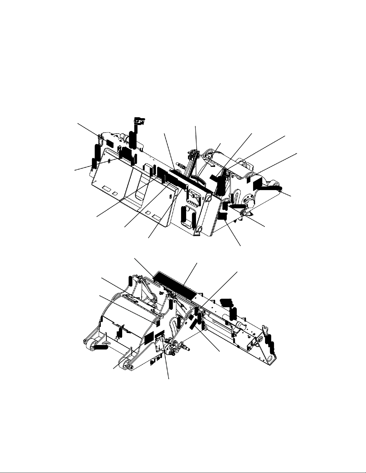
GENERAL INFORMATION DECAL PLACEMENT
The diagrams on this page show the location of the decals used on your attachment.
The decals are identified by their part numbers, with reductions of the actual decals located on
the following page. Use this information to order replacements for lost or damaged decals. Be
sure to read all decals before operating the attachment. They contain information you need to
know for both safety and product longevity.
SERIAL TAG
LOCATION
# LAF8231
# RDL3303
# 50-0737
# RDL3303
# RDL3302
# 50-0769
# 50-0724
# RDL3100
# 41043
# RDL3159
# 50-0769
# 50-0737
# 50-10017
# 50-0737 # LAF8231
# 50-0721
# 50-0769
# 50-0769
# 50-0721
# RDL3100
# RDL3300
IMPORTANT: Keep all safety decals clean and legible. Replace all missing, illegible, or damaged safety decals.
When replacing parts with safety decals attached, the safety decals must also be replaced. Safety decals are
available, free of charge, from your local dealer or Paladin.
REPLACING SAFETY DECALS: Clean the area of application with nonflammable solvent, then wash the same
area with soap and water. Allow the surface to fully dry. Remove the backing from the safety decal, exposing the
adhesive surface. Apply the safety decal to the position shown in the diagram above and smooth out any bubbles.

MR25664
13
DECALS
# 41043 WARNING! HAZARDOUS DUST
# RDL3100 WARNING! STAND CLEAR
CAUTION
DECALS
# 50-10017 WARNING! READ MANUAL
# 50-0721 WARNING! CRUSH HAZARD
# 50-0737 WARNING! PINCH POINT
Flying debris.
Wear eye protection
when operating
this equipment.
RDL3159
# RDL3159 CAUTION! FLYING DEBRIS
FAILURE TO CONNECT MOTOR CASE
DRAIN LINE WILL RESULT IN SEVERE
MOTOR DAMAGE.
RDL3300
# RDL3300 CASE DRAIN

DECALS
MR25664
13
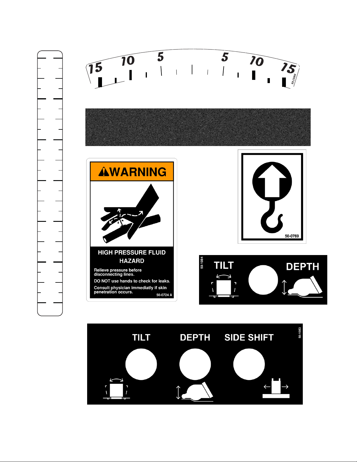
6 0
5
4
3
2
1
0
RDL3303
# RDL3303 DEPTH
SCALE
# RDL3302 TILT INDICATOR
# LAF8231 NON-SKID TAPE
# 50-0724 WARNING! HIGH
PRESSURE FLUID
# 50-0769 LIFT POINT
# 50-1084 CONTROL BOX: 5-LINE
(LOCATED ON CONTROL BOX, IF SO EQUIPPED)
# 50-1083 CONTROL BOX: 3-LINE
(LOCATED ON CONTROL BOX, IF SO EQUIPPED)
NOTE: CONTACT YOUR LOCAL DEALER FOR MODEL NUMBER
AND LOGO DECALS

14
MR25664
SKID STEER
PREOPERATION
The SPARTAN EQUIPMENT Series II High Flow Cold Planers are designed for use
on high flow prime movers. Cold planer and prime mover compatibility is determined by the
recommended lifting capacity and hydraulic output of your prime mover.
WARNING! Do NOT attach or operate any attachment that exceeds the recommended
lifting capacity of your prime mover.
Prime movers MUST be equipped with high flow auxiliary boom hydraulics, case drain
and either a Paladin electrical control box assembly or an auxiliary electrical connector on the
front of the prime mover.
WARNING! EXPOSURE TO RESPIRABLE CRYSTALLINE SILICADUST ALONG
WITH OTHER HAZARDOUS DUSTS MAY CAUSE SERIOUS OR FATAL
RESPIRATORY DISEASE.
This attachment is designed to plane (mill) rock, concrete and asphalt,
causing high levels of dust. It is recommended to use dust suppression,
dust collection and if necessary personal protective equipment during the
operation of the planer or of any attachment that may cause high levels of
dust!
IMPORT
ANT
Concrete and masonry products contain silica sand. Quartz, which is a form of
silica and the most common mineral in the earth's crust, is associated with many types
of rock.
Some activities that silica dust may be present in the air include demolition,
sweeping, loading, sawing, hammering, drilling or planing of rock, concrete or masonry.
It is recommended to use dust suppression (such as water), dust collection (such
as a vacuum) along with personal protective equipment if necessary during the opera-
tion of any attachment that may cause high levels of silica dust.
OPTIONS
Specialized Picks Contact Dealer
2.5" (Slot Cutter) Drum #LAF5404-0000
4.0" (Slot Cutter) Drum #LAF5405-0000

INSTALLATION
MR25664
15
GENERAL INFORMATION
The following instructions will help you to mount your planer onto your prime mover. The
planer uses the quick-attach system for ease of installation. Therefore, if you know how to at-
tach your loader bucket, attaching the cold planer should prove no problem.
Remember to read all safety warnings, decals and operating instructions before operat-
ing the attachment. If there is any portion of this manual that you do not understand, contact
your dealer.
WARNING! THE HIGH FLOW PLANERS ARE DESIGNED FOR USE ON HIGH FLOW
HYDRAULIC SYSTEMS.
DO NOT ATTACH OR OPERATE ANY ATTACHMENT THAT EXCEEDS THE
RECOMMENDED LIFTING CAPACITY OF YOUR PRIME MOVER.
WARNING! READ MANUAL PRIOR TO INSTALLATION
Improper installation, operation, or maintenance of this equipment could result in se-
rious injury or death. Operators and maintenance personnel should read this manual,
as well as all manuals related to this equipment and the prime mover thoroughly
before beginning installation, operation, or maintenance. FOLLOW ALL SAFETY
INSTRUCTIONS IN THIS MANUAL AND THE PRIME MOVER'S MANUAL(S).
INSTALLATION
NOTICE! Lubricate all grease fittings before connecting this product to your prime
mover's hydraulic system. Refer to Lubrication section and follow the instructions.
1. Place this product on a firm, level surface that is large enough to safely accommodate
this product, your prime mover and all workers involved in the mounting process.
2. Following all standard safety practices and the instructions for installing an attachment
in your prime mover operator’s manual, install the attachment onto your loader.
WARNING! To avoid serious personal injury, make sure the attachment is securely
latched to the attachment mechanism of your unit. Failure to do so could
result in separation of the attachment from the prime mover.
3. Relieve any pressure from the auxiliary hydraulic system. After making sure that there
is not any foreign matter on the hydraulic couplers connect the case drain coupler to the
case drain on your skid steer loader. NOTE: The case drain line must be connected first,
then the power and return hoses. When disconnecting the hoses, it is recommended to
disconnect the case drain line last.
4. Connect the power and return couplers to the high flow auxiliary hydraulic system of your
skid steer loader. Route the hoses in such a fashion as to avoid pinching or chafing.
CAUTION! BE SURE CASE DRAIN COUPLER IS COMPLETELY ENGAGED. Immediate
hydraulic motor seal failure and planetary damage will occur if case drain
is not successfully connected.

16
MR25664
INSTALL
A
TION
5. Connect the electrical wire harness from the cold planer to the auxiliary electrical con-
nector on the front of the skid steer (if so equipped). If your prime mover is not equipped
with an electrical connector and you are using the Paladin control box see the following
instructions for installing power to the control box and then connect the wiring harness
form the planer to the control box located inside of the operator’s station.
6. Cycle the hydraulic cylinders on this product several times from fully retracted to fully
extended until all air has been completely removed from the cylinders.
7. Carefully raise the loader and cycle the tilt cylinders to check clearances and to verify
that all mounting procedures have been successfully completed.
WARNING! Do not lock the auxiliary hydraulics of your prime mover in the "ON"
position. Failure to obey this warning could result in death or serious
injury.
ELECTRIC CONTROL BOX INSTALLATION
MATERIALS NEEDED: Nylon cable ties.
1. Attach the control box to a location convenient for the operator to control the planer
without hindering operation of the prime mover. Use the magnet on the back of the con-
trol box to secure the control box with the toggle switches on top.
CAUTION! Failure to obey the following procedures may result in personal injury. To
avoid electric shock during the wiring harness installation, remove the
ground cable from the battery of your prime mover.
DANGER! BATTERY ACID CAUSES SEVERE BURNS. Batteries contain sulfuric acid.
Avoid contact with skin, eyes or clothing. Antidote: EXTERNAL - flush with
water. INTERNAL - drink large quantities of water or milk. Follow with milk
of magnesia, beaten eggs or vegetable oil. Call physician immediately.
EYES - flush with water for 15 minutes and get prompt medical attention.
WARNING! When working around batteries, remember that all of the exposed metal
parts are “live”. Never lay a metal object across the terminals because a
spark or short circuit may result.
2. Disconnect the prime mover’s battery.
3. Remove the nut from the positive cable clamp and slide the red (positive) wire ring
terminal from the wiring harness over the cable clamp bolt. Secure the ring terminal with
the nut.
4. Remove the nut from the negative cable clamp and slide the black (negative) wire ring
terminal from the wiring harness over the cable clamp bolt.
5. Route & secure the wiring harness from the control box to the battery with nylon cable ties.

INSTALLATION
MR25664
17
NOTICE! Route wires away from hot and/or moving parts to avoid wire damage.
6. Verify wiring is correct and reconnect the battery.
7. Feed the wiring harness cable from the control box to the rear of the prime mover, past
the load arm’s hinge point by following the hydraulic hoses where possible.
8. Continue routing down the loader arm, following the hydraulic hoses.
9. Secure the male connector to the hydraulic lines next to the quick couplers.
10. Straighten the cable and secure it to the hydraulic lines using nylon cable ties, working
towards the rear.
11. Secure the cable to the prime mover below the hinge point and back to the control box.
NOTICE! Ensure there is sufficient slack in the cable to allow for a full range of motion
of the loader arms.
12. Connect the female electrical connector from the attachment to the male connector on
the prime mover.
DETACHING
1. Center the planer on the sideshift frame.
2. Adjust depth and tilt setting to "0".
3. Set cold planer on a firm level surface.
4. Before exiting the prime mover, lower the attachment to the ground, apply the brakes,
turn off the prime mover’s engine, and remove the key.
5. Follow prime mover operator’s manual to relieve pressure in the hydraulic lines.
6. Disconnect the power, return & case drain hoses from the auxiliary hydraulics; discon-
necting the case drain last.
7. Disconnect the electrical wire harness from the auxiliary electrical connector or Paladin
control box and after turning the ball valve to the shut off position, disconnect the water
line at the couplers.
8. Following all standard safety practices & the instructions for disconnecting an attach-
ment in your prime mover operator’s manual, disconnect the planer from your prime
mover.
9. Connect hydraulic couplers together or install caps to prevent contaminants from enter-
ing the hydraulic system. Store hoses off of the ground to help prevent damage.

OPERATION
18
MR25664
INTENDED USE:
The SPARTAN EQUIPMENT Series II High Flow Cold Planers are designed to plane /
mill horizontal sur- faces consisting of rock, concrete and asphalt. Use in any other way is
considered contrary to the intended use.
GENERAL INFORMATION
The planer attaches to the toolbar/quick-attach mechanism of your prime mover. Due to
this arrangement, thorough knowledge of the prime mover controls is necessary for machine
operation. Read and understand your prime mover operator's manual for information regarding
prime mover operation before attempting to use the planer.
Check the surface to be planed. The standard all purpose picks can be used to mill both
asphalt and concrete. There are optional concrete picks that are recommended if the planer is
to be used extensively for concrete. These picks do not perform as well when milling asphalt,
especially in warmer weather.
Review the job at hand and determine the required depth and tilt of the cut and also the
side shift position of the planer. Best performance is obtained when the cold planer is in the
center position. Side shift should be used when visibility is a determining factor such as milling
around manholes or when milling next to an obstacle such as a building.
3-LINE HYDRAULIC ASSEMBLY - PALADIN CONTROL BOX
TILT: Tilts the planer to the left and right. Taper cuts may be used when adding or joining new
paved surfaces to existing paving. Holding the switch in the TILT position will tilt the planer to
the left or right depending on the direction of hydraulic flow. When the toggle switch is released
all movement will stop.
DEPTH: Raises and lowers the left and right skid shoe. Holding the switch in the DEPTH posi-
tion will raise or lower the planer depending on the direction of hydraulic flow. When the toggle
switch is released all movement will stop.
5-LINE HYDRAULIC ASSEMBLY - PALADIN CONTROL BOX
TILT: Tilts the planer to the left and right. Taper cuts may be used when adding or joining new
paved surfaces to existing paving. Pushing the toggle switch left or right will tilt the planer to
the left or right. When the toggle switch is released all movement will stop.
This manual suits for next models
6
Table of contents


