F.P.Z. VS6 Operating and maintenance manual

DISPOSITIVO DI INVERSIONE FLUSSO ‘VS6 / VS8 ESECUZIONE O/P’ ISTRUZIONI D’USO I
‘VS6 / VS8 O/P ESECUTION’FLOW CONVERTING DEVICES USE INSTRUCTIONS GB
LEGGERE ATTENTAMENTE TUTTE LE ISTRUZIONI E CONSERVARLE I
PLEASE READ CAREFULLY ALL INSTRUCTIONS AND KEEP THEM FOR FUTURE REFERENCE GB
SN 2116-0
®F.P.Z. effepizeta s.r.l.
Via F.lli Cervi 16/18
20049 Concorezzo - (MI) - ITALIA
Tel. +39 039 604 1820
Fax +39 039 604 1296
www.fpz.com

2/13
DICHIARAZIONE DI CONFORMITÁ ALLA DIRETTIVA MACCHINE
DECLARATION OF CONFORMITY TO THE MACHINERY DIRECTIVE
Dispositivo tipo - Device type
VS6 - VS8
1. Il dispositivo è in conformità con:
- DIRETTIVA MACCHINE CE 98/37;
- DIRETTIVA EMC CE 89/336 come modificata dalle Direttive CE 92/31 e CE 93/68;
- DIRETTIVA BASSA TENSIONE CE 73/23 come modificata dalla Direttiva CE 93/68.
È tuttavia vietata la messa in servizio prima che la macchina in cui sarà incorporato sia dichiarata
conforme con le citate Direttive.
2. Sottoposto a collaudo funzionale è risultato conforme alle caratteristiche richieste.
1. Device conforms to:
- MACHINERY DIRECTIVE CE 98/37;
- EMC DIRECTIVE CE 89/336 as ammended by the CE Directives 92/31 and 93/68;
- LOW VOLTAGE DIRECTIVE CE 73/23 as ammended by the CE Directive 93/68.
Nevertheless it is forbidden to put the device in service before the machine in which will be
incorporated is declared in conformity with the above Directives.
2. The device has been tested and meets its operating performances.
02.06
®

ITEM Denominazione IDescription GB
106 Corpo Housing
165 Otturatore Shutter
363 Supporto Support
380 Supporto Support
380.1 Supporto Support
381 Collettore Manifold
381.1 Collettore Manifold
420 Anello di tenuta Seal ring
421 Anello elastico Flexible ring
550 Attuatore pneumatico Pneumatic actuator
550.1 Attuatore elettrico Electrical actuator
555 Molla Spring
560 Grano Grub screw
562 Spina cilindrica Dowel pin
901 Vite Screw
902 Vite Screw
903 Vite Screw
904 Vite Screw
905 Vite Screw
937 Bronzina Bushing
938 Anello sostegno Supporting ring
950 Raccordo Connector
ESECUZIONE
EXECUTION
OESECUZIONE
EXECUTION
P
Comando elettrico
Electrical control
Comando pneumatico
Pneumatic control
363
555
562
937
902
165
938
420
421
106
380
904
903
550
381
905
550
950
SEZIONE CON NOMENCLATURA
SECTIONAL DRAWING WITH PARTS DESCRIPTION
3/13
363
555
562
937
902
165
938
420
421
106
380.1
904
560
901
550.1
381.1
550.1
905

INDEX
1. DEVICE DESCRIPTION 10
1.1 OPERATING PRINCIPLE AND CONSTRUCTION 10
2. GENERAL INSTRUCTIONS 10
2.1. SAFETY RULES 10
2.2. FIELD USE AND WORKING CONDITIONS 10
2.3. STORAGE AND SHIPPING 10
3. INSTALLATION 10
3.1.LAY-OUT 10
3.2. INSTALLATION SKETCHES 11
3.2.1 PRESSURE SYSTEM WITH ELECTRIC CONTROL 12
3.2.2 VACUUM SYSTEM WITH ELECTRIC CONTROL 12
3.2.3 PRESSURE / VACUUM SYSTEM WITH PNEUMATIC CONTROL 12
3.3. SYSTEM CONNECTION 12
3.4. ACTUATOR CONNECTION 12
3.4.1. ELECTRIC CONTROL 12
3.4.2. PNEUMATIC CONTROL 12
4.OPERATION 12
4.1. PRELIMINARY CHECKS 12
4.2.START-UP 12
4.3. PERIODIC CHECKS 13
5. MAINTENANCE 13
5.1. INTERNAL CLEANING INSTRUCTIONS 13
GB - 9/13

1. DEVICE DESCRIPTION
1.1. OPERATING PRINCIPLE AND CONSTRUCTION
The device is actuated by means of a horizontal sliding selector
which enables switching of the ports within approximately 0.10 sec.
It is therefore possible to change flow direction or to switch the flow
path, according to the type of installation.
The device is an all aluminum alloy construction. It is not subject to
contacts and interferences between the selector and device body.
The selector acts on special flexible teflon segments which ensure
efficient sealing between the flow chambers, and is returned and
kept in the basic position by means of a coil spring.
The device can be operated either electrically or pneumatically.
2. GENERAL INSTRUCTIONS
2.1. SAFETY RULES
CAUTION!
The flow converting devices ‘VS’ have been
designed and manufactured for use in an industrial
environment, operated by qualified personnel and
as a unit to be incorporated in a machine, which
conforms to the CE Machinery Directive.
The flow converting devices ‘VS’, like all machinery
and equipment with live and moving parts, can be
a source of serious hazards unless properly used
and protected.
The user must ensure that:
All handling, assembly, installation, connection,
maintenance and repair operations are undertaken
by qualified personnel. Such people who by their
background, training and experience as well as
through their knowledge of statutory regulations,
legislation, safety measures and operating
conditions are able to carry out any necessary
steps avoiding all possible risks to health and
damage.
Such personnel should have received all the instructions and
information, including any local legislation, and will follow this
information during the performance of any operation.
It shall be forbidden for unqualified personnel to carry out any
operation, even indirectly, on the machines and equipment.
During the installation, all the prescribed working conditions,
including any possible local requirements, shall be observed.
Additionally it is forbidden to put the unit in service before the
machines of which they are a part are declared to conform to
the CE Machinery Directive.
The user must be aware that in operation:
• there can be an increase in unit operating temperature;
• there is small loss of the fluid handled;
• the level of noise may be unacceptable in certain
applications.
CAUTION!
Before undertaking any operation ensure that the unit is
disconnected from power supply.
2.2. FIELD USE AND WORKING CONDITIONS
The flow converting devices ‘VS’ are designed for the continuous
movement of air or non-explosive, non-hazardous and non-
flammable gases and for service in non-explosive environments.
Devices are designed and manufactured to flow converting in low
pressure / vacuum applications. They are for use specifically on
low pressure blowers and vacuum pumps only.
Solid particles, however small, including dirt can cause serious
damage; therefore it is essential that such substances should be
removed from the gas by suitable filters upstream of the inlet.
There is small loss of the fluid handled.
Pressure loss through the converter, as a function of flow, is
indicated on graph below:
.
2.3. STORAGE AND SHIPPING
Store the unit in a dry place, preferably in original packaging.
Do not remove the protection plugs from the ports.
Avoid stacking anything on top of the packaging.
Handle the devices with care and avoid sudden impacts.
When handling devices (lifting, moving, in transit, storing)
appropriate procedures need to be used. This work should be
organized in a safe / secure environment, minimizing the risk of
any possible mishap. For example:
• ensure staff is adequately trained;
• use secure / stable mounting/support structures;
• wear suitable workclothes and individual protection
devices;
3. INSTALLATION
3.1. LAY-OUT
It is important that the unit is installed in a well-ventilated
environment where the temperature does not exceed 40°C.
If outside, protect the unit from direct sunlight and avoid the
possibility of water collecting in the external crevices.
Please refer to attached SI1787 for unit dimensions
0 20 40 60 80 100 120
0 0,5 1,0 1,5
mbar
psig
VS 6
m3/h
cfm
50
100
200
300
400
600
800
1000
1400
0
50
100
200
300
400
500
600
800
VS 8
Pressure loss per port
(vacuum / pressure)
0
GB - 10/13

3.2. INSTALLATION SKETCHES
3.2.1. PRESSURE SYSTEM WITH ELECTRICAL CONTROL
3.2.2. VACUUM SYSTEM WITH ELECTRIC CONTROL
3.2.3. PRESSURE / VACUUM SYSTEM WITH PNEUMATIC
CONTROL
GB - 11/13
ELECTROMAGNET
NOT ACTIVATED CONNECTION
TO THE LINE
CONNECTION
TO THE BLOWER
CONNECTION
TO THE BLOWER
ELECTROMAGNET
ACTIVATED
CONNECTION
TO THE LINE
ELECTROMAGNET
NOT ACTIVATED
CONNECTION
TO THE LINE
CONNECTION
TO THE BLOWER
CONNECTION
TO THE BLOWER
ELECTROMAGNET
ACTIVATED
CONNECTION
TO THE LINE
PNEUMATIC ACTUATOR
POSITION 1 CONNECTION
TO THE LINE
CONNECTION
TO THE BLOWER
CONNECTION
TO THE LINE
PNEUMATIC ACTUATOR
POSITION 2
Compressed
air inlet
Compressed
air inlet
CONNECTION
TO THE BLOWER

3.3. SYSTEM CONNECTION
IMPORTANT !
Ingress of foreign matter, however small, will cause serious
damage.
Such matter includes dust, sand, masonry debris, impurities in the
tubes, cutting burrs or filings, welding or soldering slag and
splatter, metal burrs and any residues from sealing and making the
tube connections.
To ensure proper installation, please note the following:
• To connect the unit to the process lines, remove the flanges
and connect via flexible tubes;
• Remember to protect the inlet with suitable filters;
• To avoid using rigid couplings, which could induce stress and
cause harmful vibrations;
• Only remove the plugs on the ports when making the final
connections;
• Select the tube size and the couplings to minimize the
pressure drop, in particular:
- Do not use tubing of a smaller diameter than the ports of
the device;
- Utilise large radius bends and avoid using elbows.
Available connection
- TF threaded flange GAS (G 1 ½”, G 2”, G 3”);
- TF threaded flange NPT (NPT 1 ½”, NPT 2”, NPT 3”);
- Sleeve MP5, MP6, MP8;
- Collector CT66, CT88, CT89;
- Adaptator for SCL V4, V5, V6 and K series
3.4. ACTUATOR CONNECTION
CAUTION!
BEFORE UNDERTAKING ANY OPERATION ENSURE THAT
THE UNIT IS DISCONNECTED FROM POWER SUPPLY.
3.4.1. ELECTRICAL CONTROL
WARNING
BEFORE UNDERTAKING ANY OPERATION ENSURE THAT
THE UNIT IS DISCONNECTED FROM THE POWER SUPPLY.
The electromagnet has been selected for service in an ambient
temperature between 0°C and +35°C at an altitude no higher than
1000 m.
Verify the identification letter engraved on the back side of the
electromagnet. Line voltage values should be consistent with
following chart:
Identification
word
Voltage
(V)
Absorbed
current
(A)
Activization
ratio ED
(%)
A 24Vdc 2.26 60
B 110Vac 0.58 60
C 220Vac 0.29 60
The current drawn refers to normal operating conditions.
Variations in the supply voltage up to ± 5% are acceptable.
IMPORTANT !
The magnet activation time (“ED”) is calculated as the time the
magnet is energized as a per cent of total cycle time and
should be equal to a maximum of 60% as indicated in table.
Exceeding this value could overheat the magnet and result in
premature failure. The maximum activation time is 5 minutes.
The electromagnets come supplied with appropriate connections
for quick installation.
The connections provided offer complete protection from water
ingress according to the norm DIN 40050 (Class IP65 level of
protection) when correctly installed using appropriate connecting
screws and sealing gaskets. In addition, units conform to
VDE0110-1/89, working voltage up to 300v, working level C
regarding class of insulation.
In order to wire the electromagnets, please use the following
instructions:
• Remove the screws located on the upper part of the
connection and extract the last one from its support
• Remove the terminal contacts from the protective cap on the
connector by use of a screwdriver.;these two components
have a release joint
• Complete the wiring following the diagram on the terminal
connections by the use of locking screws
• Reassemble in reverse order (do not forget the gaskets)
N.B. The terminal connectors and the external protection of the
connectors are able to be put in 4 different orientations. Select the
one most suitable for your installation.
IMPORTANT !
CHECK TO ENSURE PROPER GROUNDING
THE ENTIRE GUARANTEE SHALL CEASE TO APPLY WHEN
INADEQUATE PROTECTION IS PROVIDED.
3.4.2. PNEUMATIC CONTROL
ATTENTION !
Before commissioning in installation, make sure the air cylinders
are not under pressure.
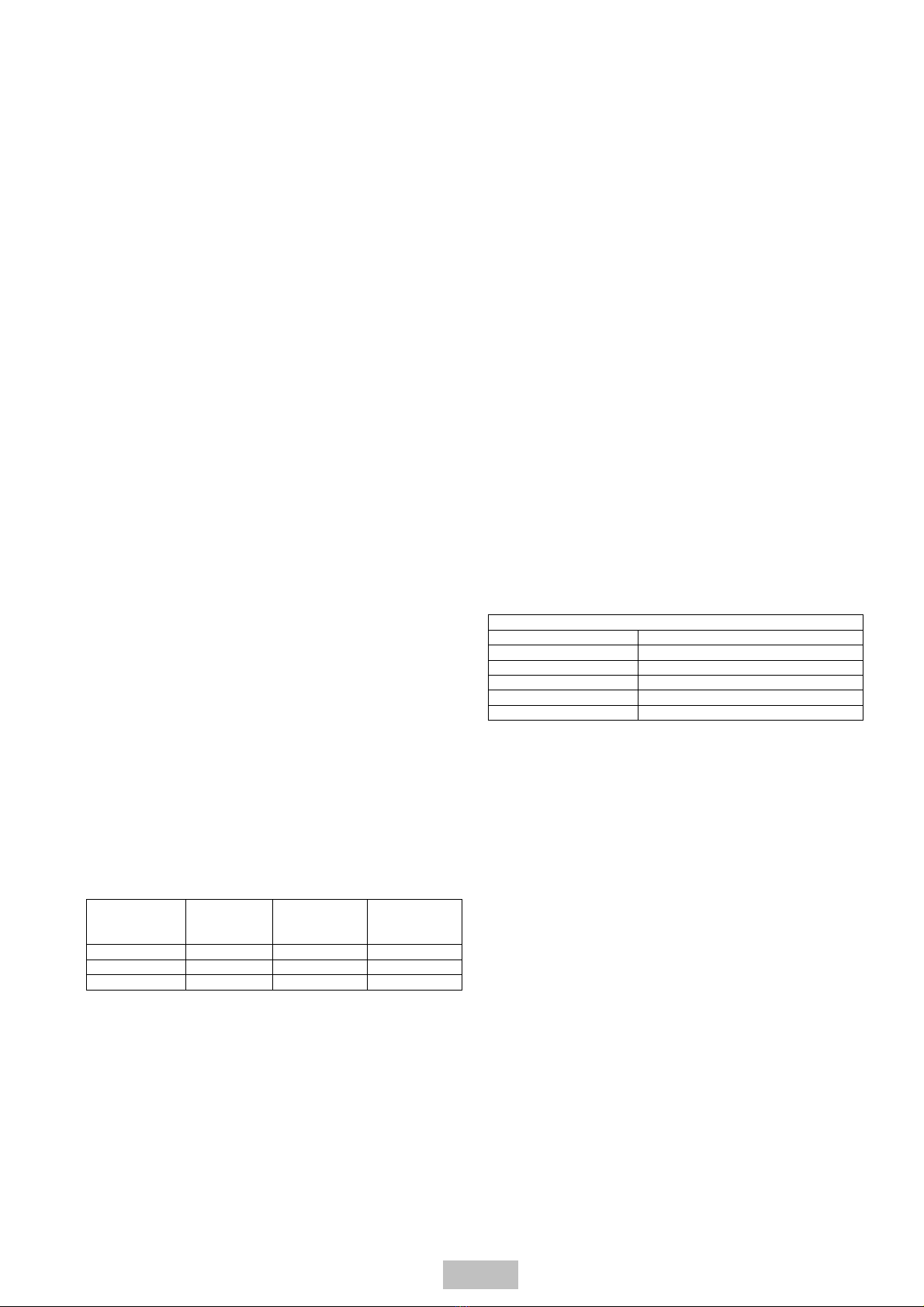
The operating characteristics for the pneumatic actuators are
described in the following table:
Pneumatic control
Thrust air cylindrer Double effect
Max pressure 10 Bar
Air consumption 0,02 litres/cycle
Operating temperature -5 °C ~ +70 °C
Fluid Filtered Air and preferably oiled
Connexion G 1/8”
Use a 1/8” nipple in the appropriate receptacle of the pneumatic
solenoid.
4. OPERATION
4.1. PRELIMINARY CONTROLS
Before commissioning, please ensure the following:
• Should the unit need to be stored for a long period of time
before installation, ensure it is kept in a dry environment and
inspect prior to installation.
• Check that there are no impurities that could obstruct the seal
between the shutter and body.
• Ensure that all safety protectors have been properly installed.
4.2. START-UP
The VS6 / VS8 flow converters do not require any additional
controls. The 2 possible positions of the shutter are fixed by run
length the shutter is not able to be put in an intermediate / half-way
position.
A higher-than-allowed differential pressure on the actuator could
cause a lack of charge in the cylinder due to misalignment of the
shutter and seal rings.
GB - 12/13

4.3. PERIODIC CHECKS
CAUTION!
BEFORE UNDERTAKING ANY OPERATION ENSURE THAT
THE UNIT IS DISCONNECTED FROM POWER SUPPLY.
Periodically check the condition of the seal rings.
In dusty / dirty envirmments increase frequency of inspection.
Departures from the normal operating conditions (unusual
operating noises, vibrations, etc.) are a sign of abnormal operation,
which can lead to failure.
Periodically remove any surface deposits which otherwise can
cause the operating temperature to rise.
In the event of difficulties please contact F.P.Z. or the relevant
sales agent.
5. MAINTENANCE
CAUTION!
BEFORE UNDERTAKING ANY OPERATION ENSURE THAT
THE UNIT IS DISCONNECTED FROM POWER SUPPLY.
MAINTENANCE OPERATIONS ARE UNDERTAKEN BY
QUALIFIED PERSONNEL (see par. 2.1 Safety rules).
5.1. INTERNAL CLEANING INSTRUCTIONS
IMPORTANT!
Internal deposit build up can cause:
• performance variations;
• misalignment of the shutter with the sealing rings, resulting in
pressure loss within the system.
Internal cleaning should be done routinely, particuliarly in dirty /
dusty environments.
The flow converter does not necessarily have to be removed from
the system for internal cleaning. Referrring to page 3, use the
following instructions:
• Disconnect the actuators;
• Disconnect the ports;
• Clean the converter body (106) and shutter (165), making sure
the seal rings (420) are not misplaced
• Reassemble in reverse order
Commitments, agreements or legal relationships are governed
by the corresponding sales contract. The above items are in
no way limited by the contents of this manual.
The quality of the materials and of the workmanship is
guaranteed as set out by the standard conditions of sales.
The guarantee is not valid for the following: damage incurred
during transport; inadequate storage; faulty installation;
incorrect use; exceeding performance limits; electrical or
mechanical miss-use.
Store the packaging for possible future use.
GB - 13/13
This manual suits for next models
1
Table of contents
Popular Water Pump manuals by other brands

Alentec & Orion
Alentec & Orion 22440 user manual

WITA
WITA HE OEM 4 40 Series Translation of original operating instructions

SKF
SKF 799-000-3035 Series Original operating instructions

Espa
Espa TIPER15 instruction manual

Crown
Crown G6 Installation and operation manual

INOXPA
INOXPA SLRT 3-90 Installation, service and maintenance instructions

Burcam
Burcam 300910 installation instructions

Faicom
Faicom GP7241 quick start guide

Ingersoll-Rand
Ingersoll-Rand PH30F-XXX-XXX-C Operator's manual

GORMAN-RUPP
GORMAN-RUPP PA6D60-4045T Installation, operation and maintenance manual

EINHELL
EINHELL NEW GENERATION NFP 750 operating instructions

Johnson Pump
Johnson Pump SPX Flow CombiLineBloc instruction manual