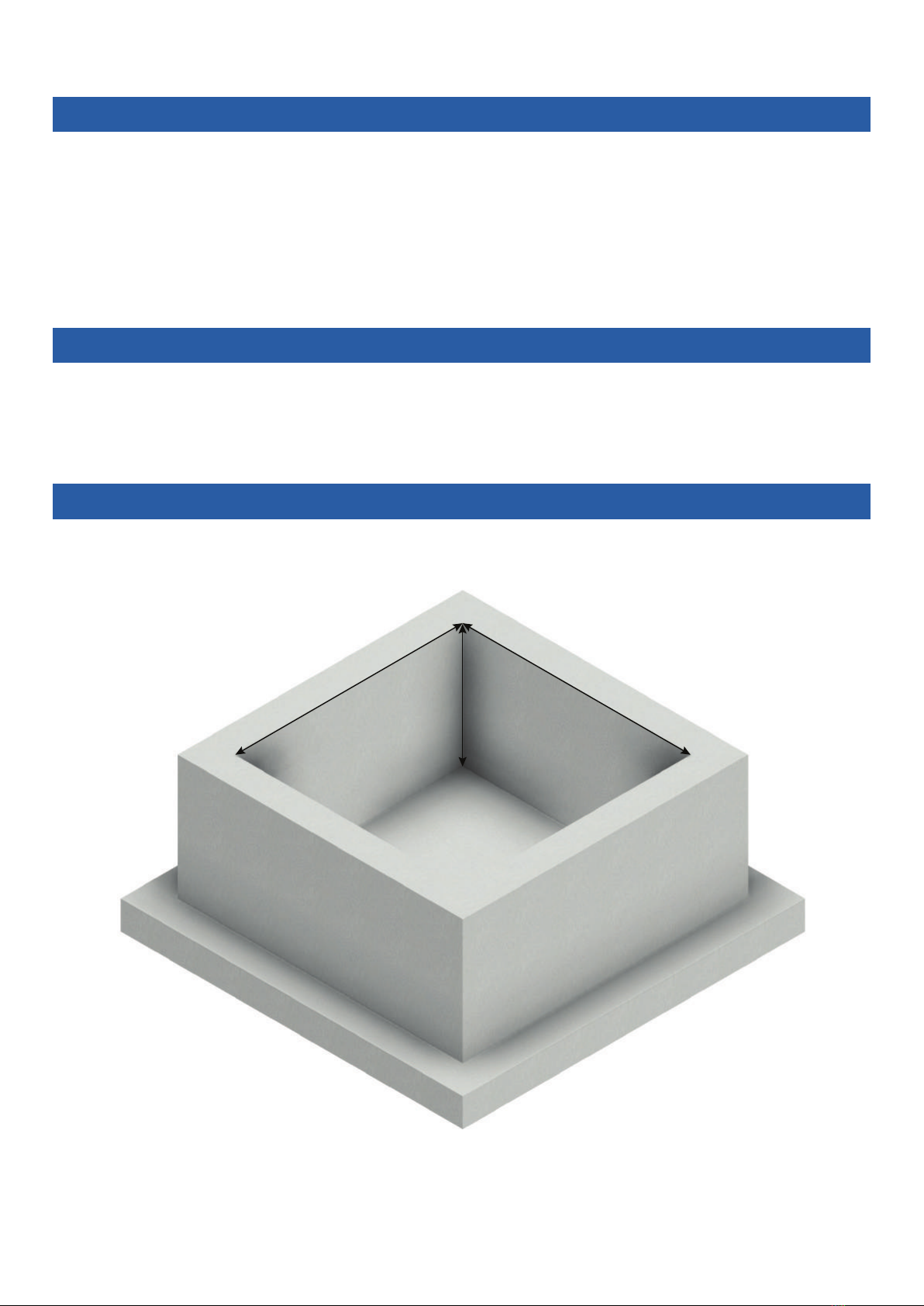
Delta Membranes Delta Foul V3 User manual

Installation Instructions
Ground Water Pump Station
Delta Foul V3 (DMS-165-1)
For Foul Water Applications
This manual is to be left
with the pump station or
the homeowner

Delta Foul V3
FV3-M-V4-11.18
Legal information/Copyright
All rights reserved. Contents provided herein must neither be distributed, copied, reproduced, edited or processed for any
other purpose, nor otherwise transmitted, published or made available to a third party without express written consent
from Delta Membranes.
Subject to technical modication without prior notice.
© Delta Membranes 2017
Delta House, Merlin Way, North Weald, Epping, Essex. CM16 6HR
01992 523 523
www.deltamembranes.com
T.
E.
W.

Contents
1.0 Foul V3 Overview 4
2.0 Parts Included 4
2.1 Optional Extras 4
3.0 Discharge Pipework & Fittings 5
4.0 Chamber Overview 6
5.0 Spare Parts 6
6.0 Technical Information 7
7.0 Pump Chamber Depth Limits 8
8.0 Installation Guidelines 9
9.0 Pump Station Location 9
10.0 RC Box Dimensions 9
11.0 Installation of Chamber 10
Section A - Construction of reinforced concrete box 10
Section B - Connecting 110mm inlet pipework 11
Section C - Connecting discharge, cable duct and vent 12
Section D1 - Backll around chamber with concrete (RC Box) 14
Section D2 - Backll around chamber with concrete (Ground) 15
Section D3 - Backll around chamber with concrete (Reinforced cage) 16
Section E - Preparing chamber for installation of pump 17
Section F - Fitting discharge to pump 18
Section G - Installing pump and high level alarm in chamber 19
12.0 Wiring Diagram (inc. AlertMaxx2) 21
12.0 Wiring Diagram (inc. AlertMaxx2 & Hi-PowerMaxx) 22
13.0 Maintenance 23
14.0 Health and Safety 23
15.0 Guarantee 23
16.0 Troubleshooting 24
Delta Foul V3
3

1.0 Foul V3 Overview
Delta Foul V3
The Delta Foul V3 is a packaged pump station designed to collect foul water. Typically, the Foul V3 would be used to
collect and discharge foul water from a basement tted with a bathroom and utility room. This pump station is not
designed to collect ground water from a cavity membrane system (see Delta Dual V3 - DMS 164). For kitchen
applications we recommend tting a grease trap prior to the pump station.
The pump station has been specically designed for below ground applications. The chamber is manufactured from HDPE
and when installed correctly, it is able to withstand hydrostatic forces encountered in high water tables.
The pump station is delivered as a complete package including all internal pipework and a D10SA foul vortex pump.
It is designed to be installed by contractors with competent building, plumbing and electrical skills.
An AlertMaxx2 (DMS-299) is oered as a recommended extra to alert the property occupant when the water level in the
chamber becomes too high. A Hi-PowerMaxx (DMS-364) is recommended to power the pump during power outage.
Please see section 2.1 for more details about optional extras designed for the Foul V3 pump station.
2.0 Parts Included
Chamber
902 x 800mm deep
2” Internal Pipework
4
D10SA Pump
(DMS-120)
2” Vent, Cable Duct &
Discharge Male Iron
for temp. site installation
2.1 Optional Extras
AlertMaxx2 High Level
Alarm (DMS-299)
2" Discharge Pipework and
various ttings
(see page 5)
Hi-PowerMaxx Battery
Backup (DMS-364)

5
Delta Foul V3
3.0 Discharge Pipework & Fittings
Part Description Part No. Qty Req.
2" Pipe - 3m Length (Class E) DMS-0154
2" 90° Elbow - Plain/Plain DMS-0155
2" 45° Elbow - Plain/Plain DMS-0156
2" Socket - Plain/Plain DMS-0157
2" Socket - BSP Female Thread/BSP Female Thread DMS-339
2" Male Iron - Plain/BSP Male Thread DMS-0153
2" Male Iron - Plain/BSP Male Thread (Non-pressure) DMS-335
110mm to 2" Adaptor DMS-341
Saddle Clamp - 110mm to 2" (BSP Female Thread) including 2" Male Iron DMS-0151
Saddle Clamp - 160mm to 2" (BSP Female Thread) including 2" Male Iron DMS-0152
2" Pipe Clip DMS-0159
500ml PVC Solvent Cement DMS-0158
Name:
Company Name:
Site Address:
Email:
Phone No.: Mobile No.:
A selection of discharge pipework and ttings are available for the Foul V3 pump station.
Should you require to place an order for any of these items, please complete the form below, scan and email to
Sign: Date:

4.0 Chamber Overview
5.0 Spare Parts
Part Description Part No.
12" Male Iron (Non-pressure) DMS-335
22" Female - 2" Male
Adaptor
DMS-337
32" Non Return Valve DMS-327
4Foul V3 Discharge Bend DMS-334
5D10SA Pump DMS-120
6Discharge Arm c/w DC65
Connector
DMS-129
6
Delta Foul V3
13 21 145
6
Part Description
AScreed
BInsulation
CMS20
DBasement Slab
EInlet Pipe
FConcrete Base
GManhole Cover
HFoul V3 Chamber
ICable Duct
JDischarge Pipe
KDistribution Board
LNon-switched Fused Spur
MVent Pipe
NAlertMaxx2
A B C D E F G H I J
K L NM
Membrane sealed to
chamber with Delta
150mm corner strip

Delta Foul V3
Pump Specication
Pump Type D10SA
Typical Duty (I/s) Head (m)
38.30
47.50
56.30
65.00
73.70
82.30
Power P1(kW) 1.15
P2(kW) 0.75
Current (a) 5.88
Power Phase Single
Non-switched Fuse Spur Rating (a) 13
RCBO Rating (a) 16
Cable Length (m) 10
Max. Temperature (°C) 35
Weight (kg) 13
Chamber Specication
Chamber Material High Density Polyethnylene - ICO1314 grade
Size (mm) Chamber Diameter 660
Overall Diameter 902 (across spigots)
Depth 800
Volume (L) Below Inlet 137
Total 273
Inspection Cover Not supplied
Clear opening to chamber (mm) 310 x 310
Fixed Inlets 3 x 110 / 160mm
Cable Duct (mm) 50
Vent (mm) 50
Discharge Connection 2" / 50mm SP Male - External to chamber
Internal Pipework Manifold 2" / 50mm BSP Class E
6.0 Technical Information
7

7.0 Pump Chamber Depth Limits
< 500mm
> 500mm
The pump chamber must be installed no more than 500mm
below oor nishes.
A pump chamber installed more than 500mm below
oor nishes cannot be serviced safely in accordance
with CDM regulations.
If the inlet does not allow the pump chamber to be within depth limits, please contact PPS on 01279 757400 to
discuss chamber options.
Delta Foul V3
8

800mm
1200mm
1200mm
8.0 Installation Guidelines
The following instructions are for guidance only and it is the contractors responsibility to ensure that the
installation is in accordance with the prevailing ground conditions and good building practice, to eliminate any
potential damage to the pump station either during or after installation.
Please read these instructions carefully prior to installing the chamber. If there is anything that is unclear, our technical help
desk is available on 01279 757400.
9.0 Pump Station Location
This station requires routine maintenance, therefore it is important that careful consideration is taken to position the
chamber in a location that allows permanent access to the chamber.
10.0 RC Box Dimensions
Delta Foul V3
9

Excavate hole for chamber. Refer to section 10.0 for RC
box internal dimensions.
Lay inlet and discharge pipework. Allow pipework to
protrude into RC box by a minimum of 100mm.
1
3
11.0 Installation of Chamber - Section A
Install re-bar as per structural engineer's drawings.
Pour concrete to form RC box as per structural
engineer's drawings.
2
4
Construction of reinforced concrete box
Delta Foul V3
10

11.0 Installation of Chamber - Section B
Saw o socket end/s, where inlet pipe/s are to
be connected.
Fit push t coupler.
5
7
Position chamber in RC box.
6
Connecting 110mm inlet pipework
Connect inlet pipework to the required chamber spigot.
8
Delta Foul V3
11

11.0 Installation of Chamber - Section C
Connecting discharge, cable duct and vent
Wrap the thread on a high pressure male iron with PTFE
tape.
Apply high pressure glue around the rst 20mm of the
external face of the discharge, cable duct and vent pipe
and internal side of their respective male iron.
9
11
Screw the high pressure male iron into the socket.
Push discharge, cable duct and vent pipe into their
respective male iron, twisting the pipe as it is pushed into
the male iron to remove any trapped air.
10
12
Delta Foul V3
12

11.0 Installation of Chamber - Section C cont.
Ensure a draw cord is pulled through the cable duct as
the cable duct is built.
13
Connecting discharge and cable duct
Delta Foul V3
13

11.0 Installation of Chamber - Section D1
Backll around chamber with concrete
To be followed when installing chamber in an RC box.
Check all pipes are connected to the chamber
correctly.
Fill void between RC box and chamber with concrete
(min. C35 grade) or as per engineer's drawings.
14
16
Completely ll chamber with water.
15
Delta Foul V3
14

15
11.0 Installation of Chamber - Section D2
Fill void between soil and chamber with concrete
(min. C35 grade) or as per engineer's drawings.
18
Completely ll chamber with water.
17
Backll around chamber with concrete
To be followed when installing chamber in the ground.
Allow concrete to cure.
19
Delta Foul V3

11.0 Installation of Chamber - Section D3
Fill void between soil and chamber with concrete
(min. C35 grade) or as per engineer's drawings.
21
Completely ll chamber with water.
20
Backll around chamber with concrete
To be followed when installing chamber in the ground with a reinforced cage.
Allow concrete to cure.
22
Delta Foul V3
16

Delta Foul V3
11.0 Installation of Chamber - Section E
Preparing chamber for installation of pump
Pump out water from chamber.
23
Manually remove any debris from chamber and
residual water using a wet vac.
24
17

11.0 Installation of Chamber - Section F
Hand tighten the discharge arm into the pump
discharge outlet.
26
Wrap the thread on the nipple glued in to the 90˚ bend
with PTFE tape.
25
Fitting discharge to pump
Delta Foul V3
18

Delta Foul V3
11.0 Installation of Chamber - Section G
19
Slide the DC65 over the discharge arm and lower the
pump in to chamber to release any trapped air. Slide the
DC65 up to join the manifold to the discharge arm.
28
Fill chamber half full with water.
27
Installing pump and high level alarm in chamber
Tighten the two screws on the DC65 to seal the
pipework.
29
When installing a high level alarm, refer to the high level
alarm installation instructions.
30

Installing pump and high level alarm in chamber
Pull the pump and high level alarm cables through the
cable duct. Coil 1m of pump and alarm cable inside the
chamber to allow for maintenance.
31
Isolate mains supply and connect the pump and
high level alarm according to the wiring diagram
overleaf.
32
Turn mains supply on and lift the pump oat to test the
water is discharging correctly.
33
To test oat switch, refer to the high level alarm
installation instructions.
34
11.0 Installation of Chamber - Section G cont.
20
Delta Foul V3
This manual suits for next models
1
Table of contents
Popular Water Pump manuals by other brands

Grundfos
Grundfos CRE Installation and operating instructions

Flowserve
Flowserve MPT 20 Installation operation & maintenance

Xylem
Xylem Bell & Gossett e-80SCXL Series quick start guide

Bestway
Bestway Built-in Sidewinder P3150 owner's manual

Pentair
Pentair U3 instruction manual

Becker
Becker VASF 1.120/1 operating instructions

Dover
Dover PSG Wilden SANIFLO H1500 HYGIENIC Series Maintenance manual

Advantage Controls
Advantage Controls GF Installation and maintenance manual

Crane
Crane Barnes UltraSTEP installation manual

MST
MST ZW Operation

GORMAN-RUPP
GORMAN-RUPP 02F1-GL Application, Installation, Operation, and Maintenance Manual

BARTON TOOLS
BARTON TOOLS HHB-150B instruction manual