6
ATTENTION: THE MOTORS ARE NOT OF AN ANTI-EXPLOSIVE TYPE. Do not
install them where flammable vapors may be present.
CONNECTING
To ensure a leak free connection, please follow these directions:
Step 1: Disassemble barb fitting, removing barb fitting from lock nut.
Step 2: Lubricate O-ring on barb fitting with dielectric grease to ease installation.
Step 3: Re-install barb fitting into female fitting.
Step 4: Secure with locking nut, turning clockwise until hand tight.
Step 5: Install output hose to barb fitting using hose clamp (ensure even cut
end on hose).
DISPENSING
After installation of the pump system is complete, connect the power supply and
start dispensing.
ATTENTION: It is the installer’s responsibility to use tubing with adequate
characteristics. Loosening of the connections (threaded connections, flanging,
gasket seals) can cause serious ecological and safety problems. Check all the
connections after the initial installation and continue to check them on a daily
basis. Tighten the connections if necessary.
DAILY USE
• If using flexible tubing, attach the ends of the tubing to the tanks. In the
absence of an appropriate slot, solidly grasp the delivery tube before
beginning to dispense.
• Before starting the pump, make sure that the nozzle is closed (dispensing nozzle
or line valve).
• Turn the ON/OFF switch to ON. The bypass valve allows functioning with the
nozzle closed only for brief periods.
• Open the nozzle, solidly grasping the end of the tubing.
• Close the nozzle to stop dispensing.
• When dispensing is finished, turn off the pump.
ATTENTION: Function with the delivery valve closed is only allowed for brief
periods (2-3 minutes maximum). After using, make sure the pump is turned off.
7
HOW TO USE THE METER
INTRODUCTION
Only low viscosity liquids are compatible with the turbine digital meter, namely:
diesel exhaust fluid, water/urea solution.
Use of other fluids may cause inaccurate measurements and can damage the meter.
Flow Rate: 3-26 gpm. Flow rates outside of this range may be incorrect.
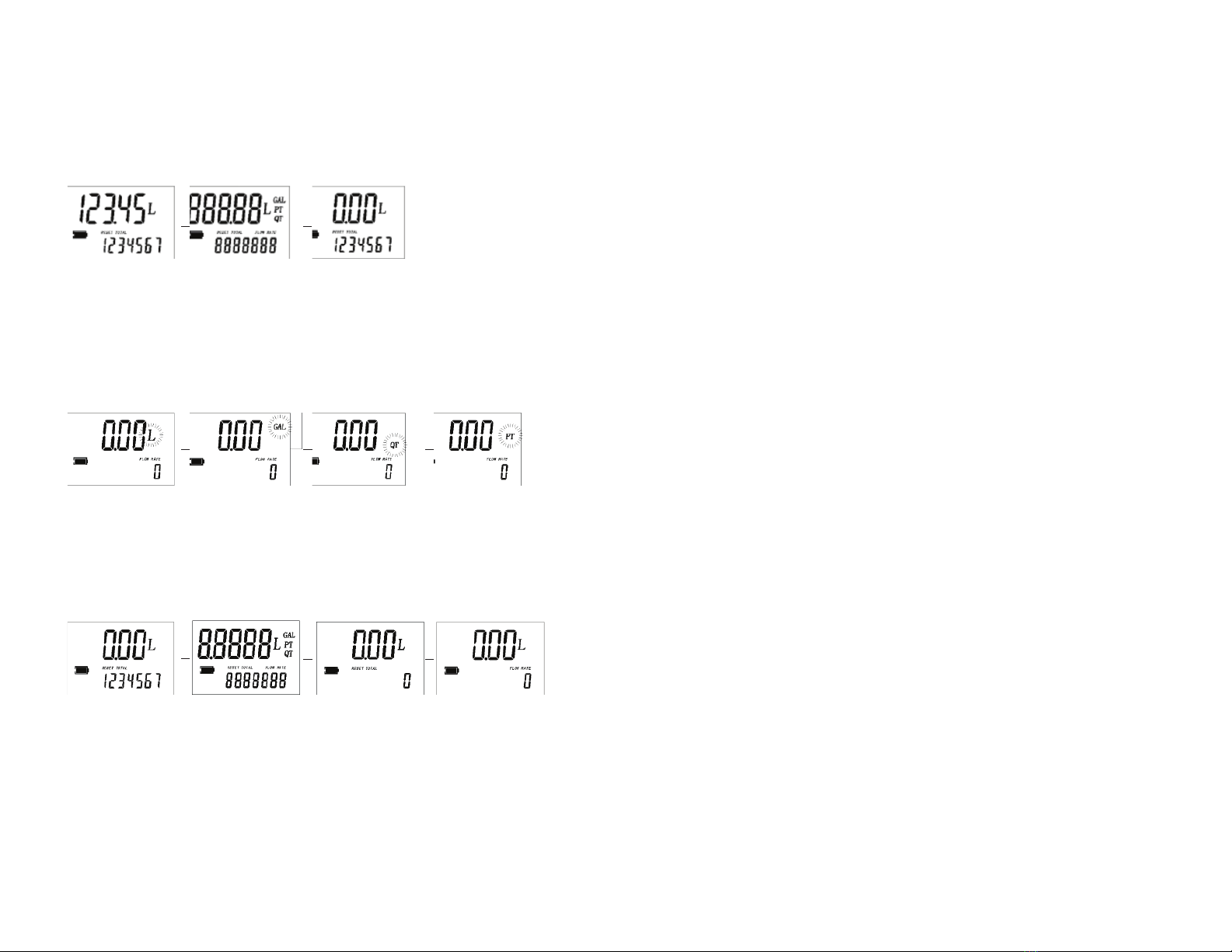
LCD DISPLAY
The LCD meter features two numerical registers and various indications displayed to
the user only when the applicable function requires.
BATTERY REPLACEMENT
To replace battery, open the cover, remove the plug and replace the battery.
KEY (Fig.2)
1. Partial register (four figures with moving comma from 0.1 to 99999) indicates
the volume dispensed since the reset button was last pressed.
2. Indication of battery charge.
3. Indication of calibration mode.
4. Indication of resetting present total to zero.
5. Total register.
6. Indication of flow rate mode.
7. Indication of unit of measurement.
USER BUTTONS
The turbine digital meter features two buttons: MENU and RESET. Individually they
perform two main functions and together, other secondary functions. The main func-
tions performed are:
RESET: Resetting the partial register and table total.
MENU: Entering instrument calibration mode.
Used together, the two keys permit entering configuration mode.
L = Liters
GAL = Gallons
PT = Pints
QT = Quarts
(Fig. 2)