FAAST 8251BPI Manual

FAAST 8251BPI and 8100
INSTALLATION AND MAINTENANCE INSTRUCTIONS
1
TABLE OF CONTENTS
Document Colour Code Key: (refer to Page 24)
Black: applies to both 8251BPI and 8100 Devices
Orange: applies to 8251BPI FAAST XM Only
Green: applies to 8100 FAAST XM Only
SPECIFICATIONS:
Electrical Characteristics
External Supply Voltage 18 –30VDC
Remote Reset Time External monitor must be pulled low for a minimum of 100msec.
Power Reset 10 secs (FAAST 8251BPI); 1 sec (FAAST 8100)
Average Operating Current 500mA @ 24VDC
Alarm Current 650mA –All relays active, all alarm levels displayed. Voltage @
24VDC
Average Loop Driver Operating Current: 700uA
Loop Driver Voltage Range: 15 –32VDC
Relay Contact Ratings 3.0A @ 30VDC, 0.5A @ 125VAC
Environmental Ratings
Operating Temperature 0°C to 38°C (32°F to 100°F)
Sampled Air Temperature -20°C to 60°C (-4°F to 140°F)
Humidity 10 to 95% (non-condensing)
IP Rating IP30
Coverage Area 1000m2(8,000ft2)
Air Movement 0 - 1,219.2 m/min. (0 –4,000 ft./min.)
Mechanical Characteristics
Exterior Dimensions 337 x 330 x 127 H x W x Dmm
Cable Access 4 x 25.4mm cable entry holes on top and bottom of unit.
Wire Gauge 2.0mm (12 AWG) max to 0.5mm (24 AWG) min.
Shipping Weight 5.26 kg, includes packing material
Nett Weight
Pipe Network Size Up to 1000m2
Maximum single pipe length 80m
External pipe diameter 25mm
Internal pipe diameter 15 - 21mm
Specifications:…………………………………………1
Introduction:……………………………………………2
Scope of this Manual……………………………….2
Description:………………………………………….…2
Features……………..………………………………2
Items Included with Unit.........…………………….2
Installation:.…………………………………………....2
Pipe Installation..…..……………………………….2
Physical Unit Installation........………………….....2
Securing the Mounting Bracket……………….2
Mounting the Detector to the Bracket………..3
Connecting the Air Sampling Pipe..…………. 3
Exhaust Pipe……………..……………………. 3
Wiring........……………………………………...…..3
Power Cables…………………………….……. 3
Conduit Usage………………………………….3
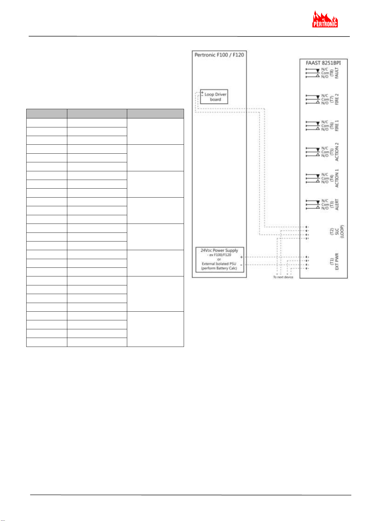
FAAST 8251BPI Cabling Requirements…….......4
FAAST 8251BPI System Powering…….……..….4
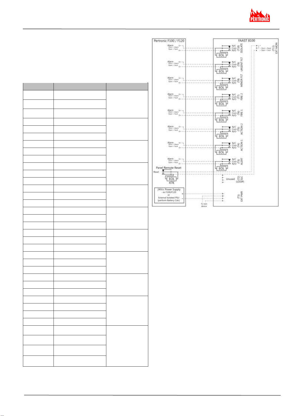
FAAST 8100 Cabling Requirements…….……….5
FAAST 8100 System Powering …………….…. 5
User Interface:.…..………………………………….... 6
FAAST 8251BPI User Interface……….………….6
FAAST 8100 User Interface……………………….6
User Interface Card Installation……………....…..6
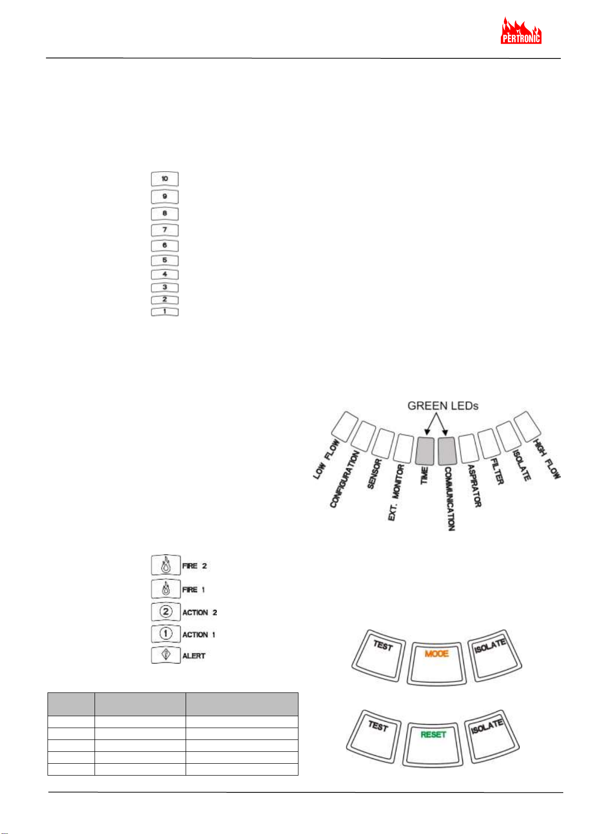
Particulate Level Display…………………..….......6
Alarm Level Display ……………………..……..….7
Alarm Level Programmable Ranges……..…. 7
Air Flow / Fault Display……..…………..……..…. 7
Labels………………………………..…………. 7
User Interface Buttons….………………………….7
Modes of Operation:……..………….…………….... 8
Initialisation…………………………...….………….8
Startup……………………………………………….8
Configuration…………………………………....…. 8
Normal Mode………………………………..….......8
Test Mode………………….……………..……..….8
Reset Mode…………..……………...….…………. 8
Acclimate…………………………………………….9
Setting Acclimate Mode………………………. 9
Day, Night and Weekend Mode……………....…..9
Isolate………………………………………..….......9
Disable………….………….……………..……..…. 9
User Button Alternate Functions…..…………….10
Passcode Access……………….…………….10
Address Blink Mode….……………………….10
IP Address Blink Mode……………………….11
Real-Time Clock..…..………………………..……11
Logs........………………………………………......11
Event Log…………………………………..….11
Data Trend Log…………….………………....11
Message Log………………………………….11
External Monitor / Reset…………………...….. 11
Ethernet Connection………………………....... 11
Faults…….…………………………………...…. 12
Pipe Network.…………………………………..… 13
Web Server………………………………….….…13
Email Notification…….………………………..….13
Canned Smoke Tests…………………………….13
Maintenance……………...............................…..13
FAAST XM Detector Base……..…………....…..13
Glossary:…………………..………….……………....14
Key Terms………………………...….……..……. 14
Document Colour Code Key………………….. 14
FAAST System Validation Form….…………….... 15

FAAST 8251BPI and 8100
INSTALLATION AND MAINTENANCE INSTRUCTIONS
2
Items Included with Unit
FAAST XM device
Mounting bracket
Mounting nuts (2) and washers (2)
3-pin terminal block 6 (8251BPI) 9 (8100)
4-pin terminal block 2 (8251BPI) 1 (8100)
47KΩ EOL Resistor 2 (8100 only)
Installation and Maintenance Instructions
PipeIQ software and a comprehensive instruction manual.
An advanced networking white paper may be downloaded
at www.systemsensor.com/faast
Figure 1: Wall Mounting Plate
INTRODUCTION
Scope of this Manual
This manual is intended as a guide for technicians to
install, set up and provide preliminary system checks for
the FAAST (Fire Alarm Aspiration Sensing Technology)
aspirating smoke detection system. Before installing,
please read the Comprehensive Instruction Manual for
the FAAST aspiration detection system (available on
PipeIQ CD or at SystemSensor.com/faast), which
provides detailed information on pipe design and system
configuration.
WARNING
The performance of the system depends on the designed
pipe network for the site. Any alteration to the pipe
network will alter the performance of the system and
must be verified by a technician. The PipeIQ® design
tool can be used to verify the suitability of any pipe
network design and subsequent alterations. The PipeIQ
software program is available from your distributor or can
be downloaded from systemsensor.com/faast.
DESCRIPTION
The 8000 Series FAAST XM aspirating smoke detection
system is an advanced particulate detection system for
use in early warning and very early warning applications.
The system continuously draws air from the controlled
environment through a series of sampling holes to
monitor the environment for smoke particulate.
FAAST system conditions are displayed at the user
interface and at a fire alarm control panel via relays.
System conditions can also be displayed remotely in two
ways through the network interface: integrated Web
server or PipeIQ software. The display provides a clear
indication of the system status, particulate levels, alarm
levels, air flow and faults. Additionally, e-mail notification
can be sent upon status changes. These can all be
discerned by monitoring the user interface at either the
local or remote display.
Features
Clip intelligent protocol (8251BPI only)
Advanced detection using blue LED and IR laser
technology
Monitors up to 1000m2(dependant on local code and
ordinances)
Wide sensitivity range of 0.0015% to 20.5% obs/m.
Programmable alarm thresholds and delays
Six (8251BPI) or eight (8100) sets of relay contacts
Advanced dust discrimination for reduced false alarms
Air filtration
Particle separation for increased filter life
Electronic filter life monitoring
Ultrasonic air flow sensing
Field service access door
Easy access filter maintenance door
Event, service and trend logs
PipeIQ pipe modelling software
Acclimate mode operation for auto-adjustment of
sensitivity
Remote monitoring via Ethernet/IP
Remote reset/dry contact input
Multi-lingual support
Email notification of alarm, fault or isolate conditions
INSTALLATION
This equipment must be installed in accordance with all
local and national codes and regulations.
Pipe Installation
The pipe layout is designed using the PipeIQ software
package. Refer to the Comprehensive Instruction Manual
that comes with the PipeIQ software package to design
the pipe network. All pipe must be installed in accordance
with local and national codes and regulations.
The pipe network should be complete before proceeding
with the physical and electrical system installation.
Physical Unit Installation
Make sure that there are no pipes or electrical wires
within the wall before drilling any mounting holes.
Securing the Mounting Bracket
The typical mounting location for the FAAST unit is on a
wall. The unit is mounted to the wall using the enclosed
mounting plate. Figure 1 shows the wall mounting plate.
For easier access to the FAAST unit, it is preferred to
position the mounting plate in an easily accessible
location.
1. Place the mounting bracket on the wall in the desired
location and use it as a template to locate the necessary
mounting holes.
2. Mark the hole locations and remove the bracket. It is
recommended to secure the bracket using the 4 outer
mounting holes.
3. Using a drill and the proper size bit for your mounting
hardware, drill the necessary holes.
4. Use appropriate fasteners to accommodate the mounting
surface and FAAST device weight.
5. Secure the bracket to the wall.
WARNING

FAAST 8251BPI and 8100
INSTALLATION AND MAINTENANCE INSTRUCTIONS
3
Figure 2: Mounting Slots for Mounting Studs
Figure 3: Power and Alarm Connector Block
Mount the Detector to the Bracket
Once the mounting plate is attached, the unit is ready to
be mounted onto the plate.
1. before installing the unit onto the bracket, remove the
appropriate conduit cap from the top or bottom-left
side of the unit to match the orientation of the wiring.
See Figure 19 for location of the wiring access plugs.
2. line up the unit with the four mounting clips and the
mounting studs on the left side.
3. push the unit down onto the mounting clips and
secure it with the supplied washer and nut on at least
one of the two mounting studs protruding through the
mounting slots shown in Figure 2.
Exhaust Pipe
The device should always be exhausted into the space
that it is monitoring. There are some circumstances when
it may be necessary to connect a pipe to the exhaust port
to divert the exhaust away from the location of the unit.
The output ports are tapered the same as the input ports,
to provide fast, easy, push-fit connection of an exhaust
pipe to the unit. Perform the following procedure to
connect the exhaust pipe to the unit.
1. square off and de-burr the end of the exhaust pipe.
Ensure that the pipe is free from any particles that
might interfere with the pipe connection.
2. remove the exhaust plug from the output port being
used (either the top or bottom of the unit).
3. insert the exhaust pipe into the output port, ensuring a
snug fit. DO NOT glue these pipes.
Wiring
Before working on the FAAST system, notify all required
authorities that the system will be temporarily out of
service. Make sure all power is removed from the system
before opening the unit. All wiring must be in accordance
with local codes.
Power Cables
Use the power ratings of the unit to determine the
required wire sizes for each connection. Use the power
ratings of the connected products to determine proper
wire size.
Conduit Usage
If electrical conduit is used for system wiring, terminate
the conduits at the cable entry ports on the top or bottom
of the unit, using the appropriate conduit connectors.
1. run all wiring, both power and alarm, through the
conduit and into the left side of the unit enclosure, as
shown in Figure 3.
2. attach the appropriate wires to the supplied Euro
connector. Follow appropriate local codes and
electrical standards for all cabling.
3. plug the appropriate connector into the mating
connector on the unit.
Connecting the Air Sampling Pipe
The input and output ports are designed to accept
standard one inch pipe (25 mm) OD. The input ports are
tapered to provide fast, easy, push-fit connection of the
sampling pipe to the unit. Perform the following
procedure to connect the air sampling pipe to the unit.
1. square off and de-burr the end of the sampling air
pipe. Ensure that the pipe is free from any particles
that might interfere with the pipe connection.
2. remove the input plug from the input port being used
(either the top or bottom of the unit).
3. insert the sampling air pipe into the input port,
ensuring a snug fit. DO NOT glue these pipes.
WARNING

FAAST 8251BPI and 8100
INSTALLATION AND MAINTENANCE INSTRUCTIONS
4
Figure 4a: 8251BPI to FACP Wiring Diagram Figure 3: Power and Alarm Connector Block
FAAST 8251BPI System Powering
The following procedure describes how to initially
power up the FAAST system.
1. unplug the unit’s power connector before turning
the power ON.
2. turn the power ON.
3. check the voltage at the connector - ensure it is
within the required voltage range.
4. if the voltage is within the proper range, reconnect
the power connector to the unit.
5. connect the Loop connector to the SLC terminal –
connections: 5/7
6. verify the system fan starts up and air begins to
flow out of the exhaust port.
Number
Name
Terminal Block
26
Fault N/C
T8
25
Fault COM
24
Fault N/O
23
Fire 2 N/C
T7
22
Fire 2 COM
21
Fire 2 N/O
20
Fire 1 N/C
T6
19
Fire 1 COM
18
Fire 1 N/O
17
Action 2 N/C
T5
16
Action 2 COM
15
Action 2 N/O
14
Action 1 N/C
T4
13
Action 1 COM
12
Action 1 N/O
11
Alert N/C
T3
10
Alert COM
9
Alert N/O
8
Analogue Loop -
T2
7
Analogue Loop -
6
Analogue Loop +
5
Analogue Loop +
4
External Power +
T1
3
External Power +
2
External Power -
1
External Power -
Table 1a: FAAST 8251BPI Terminal Designations
Notes:
a) The Terminal Blocks are numbered with T8 to the top
and T1 at the bottom
b) Terminal blocks T9 to T11 are unused
FAAST 8251BPI Cabling Requirements
The FAAST 8251BPI provides a series of Euro style
pluggable terminals, located behind the left side door of
the unit.
Refer to Table 1 for the proper electrical connections to
the unit and Figure 4 for typical connection for monitoring
a Stand-Alone FAAST system at a Fire Alarm Control
Panel (FACP).
FAAST 8251BPI to FACP Wiring Diagram

FAAST 8251BPI and 8100
INSTALLATION AND MAINTENANCE INSTRUCTIONS
5
FAAST 8100 to FACP Wiring Diagram
Figure 4b: 8100 to FACP Wiring Diagram Figure 3: Power and Alarm Connector Block
FAAST 8100 System Powering
The following procedure describes how to initially
power up the FAAST system.
1. Unplug the unit’s power connector to the unit
before turning ON the power.
2. Turn on the power.
3. Check the voltage at the connector. Make sure it is
within the required voltage range.
4. If the voltage is within the proper range, reconnect
the power connector to the unit.
5. Verify the system fan starts up and air begins to
flow out of the exhaust port.
6. Connect a computer, with the PipeIQ software
installed, to the unit using the Ethernet connection
on the bottom of the unit.
7. Use the PipeIQ software to set up the unit
configuration required for the particular application.
8. When the configuration is complete, remove the
Ethernet connection to the unit.
Table 1b: FAAST 8100 Terminal Designations
Notes:
a) the Terminal Blocks are numbered with T11 to the top
and T1 at the bottom
b) Terminal Block T2 is unused (SLC)
Number
Name
Terminal Block
35
Ext Monitor/Reset +
T11
34
Ext Monitor/Reset -
33
Ext Monitor/Reset -
32
Isolate N/C
T10
31
Isolate COM
30
Isolate N/O
29
Urgent Fault N/C
T9
28
Urgent Fault COM
27
Urgent Fault N/O
26
Minor Fault N/C
T8
25
Minor Fault COM
24
Minor Fault N/O
23
Fire 2 N/C
T7
22
Fire 2 COM
21
Fire 2 N/O
20
Fire 1 N/C
T6
19
Fire 1 COM
18
Fire 1 N/O
17
Action 2 N/C
T5
16
Action 2 COM
15
Action 2 N/O
14
Action 1 N/C
T4
13
Action 1 COM
12
Action 1 N/O
11
Alert N/C
T3
10
Alert COM
9
Alert N/O
8
N/A
T2
7
N/A
6
N/A
5
N/A
4
External Power +
T1
3
External Power +
2
External Power -
1
External Power -
FAAST 8100 Cabling Requirements
The FAAST 8100 provides a series of Euro style
pluggable terminals, located behind the left side door of
the unit.
Refer to Table 1 for the proper electrical connections to
the unit and Figure 4 for typical connection for monitoring
a Stand-Alone FAAST system at a Fire Alarm Control
Panel (FACP).

FAAST 8251BPI and 8100
INSTALLATION AND MAINTENANCE INSTRUCTIONS
6
Figure 5a: FAAST 8251BPI User Interface Display Figure 5b: FAAST 8100 User Interface Display
FAAST 8125BPI USER INTERFACE
The user interface, shown in Figure 5a, provides the
following information:
Detector Status: Normal, Alarm, Fault or Isolate
Alarm Level; Alert, Action 1, Action 2, Fire 1 and Fire 2
Particulate Levels; 1-10 relative to user programmable
scale
Fault Status
Flow Level
Test, Mode and Isolate Buttons
User Interface Card Installation
The user interface card must be installed on the front
panel of the FAAST aspirating smoke detection system.
For installation, first slide the card into the bottom pocket,
then beneath each of the mounting tabs. If necessary,
use a flathead screwdriver to gently press the card in
place beneath each of the mounting tabs. The card is
moderately flexible to allow for some bending during
installation. The user interface card is available in various
languages.
FAAST 8100 USER INTERFACE
The user interface, shown in Figure 5b, provides the
following information:
Detector Status: Normal, Alarm, Fault or Isolate
Alarm Level; Alert, Action 1, Action 2, Fire 1 and Fire 2
Particulate Levels; 1-10 relative to Alert
Fault Status
Flow Level
Test, Reset and Isolate Buttons

FAAST 8251BPI and 8100
INSTALLATION AND MAINTENANCE INSTRUCTIONS
7
Figure 6: Particulate Level Display
Figure 8: Balanced Air Flow
Figure 7: Alarm Level Display
Alarm Level Programmable Ranges
Table 2: Alarm Level Programmable Ranges
Alarm
Level
Default Threshold
(% Obs/m)
Programmable Range
(% Obs/m)
Alert
0.0396
0.0015 –20.5
Action 1
0.165
0.0033 –20.5
Action 2
0.33
0.0102 –20.5
Fire 1
0.825
0.039 –20.5
Fire 2
1.65
0.039 –20.5
AirFlow/Fault Display
The FAAST system uses ultrasonic airflow sensing and
displays the status in real time on the User Interface. The
air flow/fault display consists of 10-bicolor LEDs and
operates in one of two modes. A fault warning occurs
when airflow increases or decreases by 20% or greater.
The green segments indicate how close the current air
flow is to either of these thresholds. During normal
operation two adjacent indicators are green and
correspond to the current airflow entering the detector.
When airflow is at a balanced level the two green
segments are centred on the graph at levels 5 and 6, see
Figure 8. As airflow rises and falls, the green segments
move right and left accordingly. The segment on the far
left represents a decrease in airflow of 20%. Conversely,
movement to the segment on the far right represents an
airflow increase of 20%. A flow fault occurs within 3
minutes of reaching either of these levels and a Fault
relay operates:
- 8251BPI: the sole Fault relay de-activates
- 8100: for an airflow change exceeding 20-30% of
Normal the Minor Fault relay operates.
- for an airflow change exceeding 50%, the Urgent
Fault relay operates
During a fault condition, the Fault LED as well as the
corresponding High or Low Fault segment is lit in amber.
Labels
Detector faults are labelled adjacent to the indicators on
the Air Flow Fault graph.
User Interface Buttons
The User Interface has three buttons, shown in Figures
9a (8251BPI) and 9b (8100) that are used to operate the
unit. Functionality of these buttons are locked out by
default from the factory and require a Passcode to enable
them (refer to Passcode Access section). The passcode
can be programmed from PipeIQ.
Particulate Level Display
The particulate level display, shown in Figure 6, consists
of ten amber LEDs that correspond to the current level of
the particulate detected. The LEDs illuminate in order
from Level 1 to Level 10, starting from the bottom of the
display and moving up as the particulate level increases.
Each LED represents a ten percent increase in the
particulate level necessary to reach the Alert Alarm Level
(FAAST 8100) or the level programmed by the User
(FAAST 8251BPI).
Alarm Level Display
The Alarm Level Display consists of five red LEDs that
correspond to the current Alarm level, shown in Figure 9.
These LEDs are located directly above the Particulate
Level LEDs. They illuminate sequentially upward as the
severity of the Alarm increases.
These Alarm levels are configured at default levels when
shipped and each Alarm level controls a set of Form-C
relay contacts.
Control of the Alarm level is:
- 8251BPI : from the F100/F120 Configuration
- 8100 : modified using PipeIQ
When an Alarm level threshold is crossed, the
corresponding level LED illuminates and the relay
activates a signal. These Alarm levels and associated
relay outputs can be programmed for either latching or
non-latching operation, in addition to a programmable
delay for each level from 0 to 60 seconds.
The programmable ranges for each level are shown in
Table 2.
Figure 9a: 8251BPI User Interface Buttons
Figure 9b: 8100 User Interface Buttons

FAAST 8251BPI and 8100
INSTALLATION AND MAINTENANCE INSTRUCTIONS
8
MODES OF OPERATION
Initialisation
When the FAAST system is first installed it is not
configured and gives a fault indication by illuminating the
configuration fault LED indicator. This indicates that the
device has not had its initial configuration loaded and
remains in this state until it is initially configured (refer to
the Configuration section below for further instructions).
Once configuration has started, the device performs an
automatic initialization. This initialization sets the air flow
baseline, the filter clogged baseline and the particulate
level baseline. It is important that the system is
connected properly and the filter is installed correctly
when the device is initialized. These initial readings are
used as a reference baseline to indicate when a fault
occurs. Initialization may take up to five minutes to
complete.
Startup
Once powered, the FAAST system scrolls the particulate
display in green for one second and then initializes using
its stored configuration. The device checks and
establishes its initial airflow, filter and fan settings. If all
measurements are normal it begins normal operation. If
any fault is detected the appropriate Fault LED
illuminates.
Configuration
The FAAST system is configured using the software
included in PipelQ. Data is sent via the built-in Ethernet
connection. The device receives the configuration and
performs a validation before the configuration becomes
active. After validation of the data, the device performs
an initialization with the new configuration.
Address Assignment
The loop address for a FAAST 8251BPI unit is set using
the PipeIQ software. Each unit uses one loop address.
To assign the device a loop address, navigate to the
‘Network’ tab in the ‘Configuration’ portion of the PipeIQ
project. Use the ‘Identification Number’ drop box at the
top of the page to assign an address of 1 through 99.
Each loop can support a maximum of 99 x analogue
addressable FAAST devices.
Failure of Configuration Validation
If configuration validation fails, the software configuration
tool indicates a failure and the FAAST system illuminates
the amber CONFIGURATION fault LED on the user
interface. The device will not accept any of the data as
valid.
If a configuration fault occurs during the initial
configuration or the device is unable to operate due to
the configuration, the Urgent Fault relay will be set. The
device must be re-configured using PipeIQ. If the
configuration fault occurs after the initial configuration
has been accepted, the Minor Fault relay will operate and
the device reverts back to its last valid configuration.
Power or Network Loss during Configuration
During an upload of configuration data, the FAAST
system keeps the last known valid configuration in
memory until a complete validation is completed on the
new configuration data. This prevents data corruption in
the event of a power loss or network failure. When power
is restored the device performs a Startup with the last
valid configuration. The device also indicates a
CONFIGURATION fault on the user interface and sets
the Minor Fault relay. This occurs only once - when the
next Reset or Power On Reset is performed the device
continues to use the last valid configuration.
Normal Mode
In Normal operating mode the FAAST system displays
the air flow and current particulate levels on the user
interface. The particulate level is compared to the
threshold levels programmed into the device and
activates the appropriate alarm as particulate levels
exceed that threshold. If any fault occurs it activates the
corresponding fault LED and relay.
Test Mode
8251BPI: Test mode is initiated through the F100/F120
or by depressing the TEST button on the user
interface, when the button is enabled (refer to
passcode access section for activation details).
8100: Test Mode is initiated through the PipeIQ Live
View tab or by depressing the TEST button on the
user interface, when the button is enabled (refer to
passcode access section for activation details). Test
mode simulates a fire condition, activating all ten
segments in the Particulate Level display and each
segment in the Alarm display. Each corresponding
alarm relay is also activated after any programmed
delay associated with that relay. Activation of the
RESET button removes the device from TEST mode
Reset Mode
FAAST 8100 Reset Mode is initiated through the PipeIQ
Live View tab or by depressing the RESET button on the
user interface, when the button is enabled (refer to
passcode access section for activation details). When
RESET is activated all relays are Reset. The device then
enters Normal mode operation. If any Fault or Alarm
states remain, the device re-activates the state
automatically.

FAAST 8251BPI and 8100
INSTALLATION AND MAINTENANCE INSTRUCTIONS
9
Table 3: Alarm Level Programmable Ranges
Alarm
Level
Threshold
High Sensitivity
Threshold
High Sensitivity
Current
Level
Alert
Alert High
Alert Low
Acclimate Alert Level
Action 1
Action 1 High
Action 1 Low
Acclimate Action 1 Level
Action 2
Action 2 High
Action 2 Low
Acclimate Action 2 Level
Fire 1
Fire 1 High
Fire 1 Low
Acclimate Fire 1 Level
Fire 2
Fire 2 High
Fire 2 Low
Acclimate Fire 2 Level
Day, Night and Weekend Mode
If Acclimate mode is not desired, the FAAST system can
operate in a simple Day, Night and Weekend mode. This
allows the device to have separate threshold levels for
each state. Times can be configured for entering and
leaving day and night time operation. The device has an
internal time reference (clock) and automatically switches
to the weekend mode for Saturday and Sunday.
Isolate
Isolate mode is initiated by pressing and releasing the
ISOLATE button on the user interface when the button is
enabled (refer to the passcode section). When the
ISOLATE button is activated the FAAST system resets
the Fault and Alarm relays. It then sets the Isolate relay
and the ISOLATE Fault indicator illuminates on the user
interface. In this mode the device operates normally but
will not activate relays for any Alarm or Fault levels
(except the Isolate relay). Fire and Fault events can still
be seen on the user interface and the web server sends
email notification of events, if enabled. Isolate mode will
be held through Resets and power outages. The device
will remain in Isolate mode until removed by pressing the
ISOLATE button. Isolate mode may be enabled and
disabled using Monitoring mode in PipeIQ.
Disable
Disable mode is initiated by pressing and holding the
ISOLATE button on the user interface for 3 seconds
when the button is enabled (refer to the Passcode
section). When the ISOLATE button is activated, the
FAAST system resets the Fault and Alarm relays. It then
sets the Isolate relay and the ISOLATE Fault indicator
illuminates on the user interface. In this mode the fan
switches off and the device does not report any Alarm or
Fault levels on the user interface or activate any relays
(except the Isolate relay). This mode should only be used
when the system needs to be taken off-line. This mode
will be held through Resets and power outages. The
device will remain in Disable mode until removed by
pressing the ISOLATE button. Disable mode cannot be
enabled or disabled using Monitoring mode in PipeIQ.
Acclimate
The FAAST system includes an Acclimate mode. Using
Acclimate mode, a device’s susceptibility to nuisance
alarms can be reduced providing maximum protection for
a device located in changing environments. The
sensitivity of the unit continuously adjusts over time,
within the set limits as the local environment changes.
Acclimate mode must be activated and configured using
PipeIQ
In Acclimate mode the device automatically adjusts the
alarm point between a specified minimum and maximum
sensitivity, programmed by the user. For the first 24
hours of operation the device monitors its environment.
After the initial 24 hour period, the device adjusts the
alarm point based on the particulate levels over a rolling
1 hour period. It then adjusts the alarm level starting from
the insensitive boundary, based on the stability of the
environment being monitored.
Setting Acclimate Mode
The user chooses the boundaries for each alarm level in
the Acclimate mode. The FAAST system starts from the
insensitive boundary and adjusts itself to stay within the
sensitive boundary. It is also possible to have a static
alarm level by adjusting the high and low boundary to the
same level. This allows the flexibility to maintain
acclimating levels for some alarms and static levels for
others. Table 3 shows the various levels that are
available.
Each Acclimate level is also available for monitoring with
the PipeIQ tool. This allows the user to read the current
Acclimated alarm level for each alarm.

FAAST 8251BPI and 8100
INSTALLATION AND MAINTENANCE INSTRUCTIONS
10
Figure 11a: 8125BPI Address Blink Mode
Figure 10: 8000 Series User Interface Buttons
Figure 11b: 8100 Address Blink Mode
Address Blink Mode
- 8251BPI
User Button Alternate Functions
Passcode Access
The user interface has an option that requires users to
enter a security code before the front panel functions
become active. All passcodes must be 4 digits in length
using numbers 1 through 9 (0 cannot be used).
Passcodes may only be changed using PipeIQ software.
PipeIQ is also capable of locking out buttons individually,
so that certain buttons may be accessed without a
passcode, if desired.
The default passcode is ‘1111’.
The TEST button enters digits, the MODE/RESET button
is used to enter the unlock mode and the ISOLATE
button increments the current digit.
To enter the passcode mode, press and hold the
MODE/RESET button for 8 seconds - the first segment
on the flow indicator first illuminates yellow, then green.
When the segment illuminates green, release the
MODE/RESET button. The first segment on the airflow
display blinks green, indicating the device is ready to
accept the first digit.
To enter the passcode, use the ISOLATE and TEST
buttons, shown in Figure 10.
The ISOLATE button is used to increment the current
digit. As the current digit is incremented the segments of
the Particulate Bar Graph illuminate accordingly.
To complete entry of the digit, press the TEST button. As
each digit is entered the airflow segment illuminates solid
green and the next segment begins to flash, indicating
the next digit is ready to be entered. After the 4th digit is
entered, the Fault indicator illuminates green, if the
passcode was accepted and remains green as long as
the detector is “unlocked”. If the passcode was not
accepted, the Fault indicator illuminates amber for 3
seconds then the device returns to its previous state.
Once the passcode is accepted, the locked out button(s)
become active. After 45 seconds of inactivity the Fault
indicator begins to blink green. After an additional 15
seconds the detector re-locks the button(s) and returns to
Normal operation.
Note: If the RESET button is chosen as a locked button,
and a Reset is initiated, the device requires the
passcode to regain access to the RESET button.
The FAAST 8100 has two types of addressing
capabilities. In addition to the IP Address, the FAAST
system can also have a local address that is assigned
through the configuration software. The address can be
between 1 and 255. This address can be accessed from
the user interface by pressing and holding the RESET
button for 3 seconds. After 3 seconds, the first segment
on the airflow display illuminates amber, shown in Figure
10, indicating the device is in address blink mode.
Release the RESET button and the device shows the 3
digit number assigned by lighting the particulate bar
graph with the appropriate number of segments for each
digit. The current digit displayed is indicated by the 3 left
most indicators on the air flow graph. The first digit is the
100’s and illuminates for 2 seconds. Next, the tens digit
illuminates for 2 seconds, followed by the ones digit
illuminating for 2 seconds. If one of the numbers is zero,
then no lights will illuminate for that number on the
particulate graph.
The device then returns to Normal operating mode.
The FAAST 8251BPI can output its’ 3-digit address
through the user interface. This can be accessed from
the user interface by pressing and holding the MODE
button for 3 seconds. After 3 seconds the first segment
on the airflow display turns amber indicating the device is
in Address Blink mode. Release the MODE button and
the device gives the 3-digit address by lighting the
particulate bar graph the appropriate number of
segments for each digit. The current digit displayed is
indicated by the 6 left-most indicators on the airflow
graph. The first 3 segments are the loop.
- 8100

FAAST 8251BPI and 8100
INSTALLATION AND MAINTENANCE INSTRUCTIONS
11
Figure 12: IP Address Blink Mode
Figure 13: IP Address Indicator Lights
IP Address Blink Mode
If the device IP has been lost or is unavailable, it is
possible to obtain the address using the IP address blink
mode. The IP address can be accessed from the user
interface by pressing and holding the MODE/RESET
button for 30 seconds. The digits are displayed using the
method as described in the Address Blink mode, except
that the FAULT and LOW VOLTAGE indicators are used
to show the 1st and 12th digit, respectively. The device
gives the 12 digit number by illuminating the particulate
bar graph to the appropriate number of segments for
each digit, as shown in Figure 12. This example shows
that the 5th number of the IP address is 7. The current
digit displayed is indicated by the FAULT, FLOW /
FAULT and VOLTAGE indicators (Figure 13) starting with
the FAULT for the 1st digit, progressing through the
HIGH FLOW, and ending with the LOW VOLTAGE for
the 12th digit. If one of the numbers is zero, then no lights
will illuminate for that number on the particulate graph.
The device will return to Normal operating mode.
Real-Time Clock
The unit is equipped with a real-time clock and power
supply that allows the FAAST system to maintain the
date and time for up to 72 hours after a loss of power.
Date and time are configured through PipeIQ. The real-
time clock is used to maintain a time base for the device.
This time base is used to time stamp all log entries, as
well as determine when it is time to transfer from Day,
Night and Weekend modes. If the device loses power for
more than 72 hours the device sets the TIME fault
indicating the time needs to be updated.
Logs
Event Log
The FAAST system is equipped with internal memory
that can be configured to log detector events. Up to
18,000 events can be stored. Events that are tracked
include Alarms, Faults and User Actions. Event tracking
data may be accessed via the network through the
PipeIQ software or the Web server interface.
Configuration and management of the log are done using
the PipeIQ software.
Data Trend Log
The FAAST system tracks trend data for each 24 hour
time period, up to 1 year. The device records the
minimum, maximum and average reading of the sensor
and flow values for each day.
Message Log
The message log allows the user to enter generic text
messages into the system’s memory. Messages may be
retrieved for viewing at a later time. These messages
may be used to track service history, configuration
changes, etc. 300 messages maximum may be stored.
External Monitor / Reset
The FAAST 8100 has an external monitor that can detect
an open or short when the 47KΩ End of Line resistor
supplied is used. When the device senses an open-circuit
it sets the External Monitor fault indicator and sets the
Minor Fault relay. When a short-circuit is detected the
device performs a Reset, providing the ability to Reset
latched Alarms remotely.
Ethernet Connection
The FAAST is a network capable device compatible with
standard Ethernet networking equipment. Connectivity is
provided by an on-board RJ45 connector located on the
base of the unit –refer to Figure 15. The network
interface is required for initial configuration of the FAAST
8100. Once initial setup is complete, the Ethernet
connection provides optional remote access, monitoring
and email notification using the unit’s Web server and
SMTP client.

FAAST 8251BPI and 8100
INSTALLATION AND MAINTENANCE INSTRUCTIONS
12
Faults
Number
Name
Description
8100
Activated Relay
1
Low Flow
8251BPI : Device has decreased airflow
Fault
8100 : Device has decreased airflow of 20%
Minor Fault
8100 : Device has decreased airflow of 50%
Urgent Fault
2
Configuration
Configuration of device with Configuration software has failed
Minor Fault
Device was interrupted with a power loss during configuration.
Reset clears this fault and the device reverts to last good
configuration
Minor Fault
Device is new and has not been configured
Urgent Fault
Device has corrupt configuration and is unable to operate
Urgent Fault
3
Sensor
Device has problem with the particulate sensor and needs
immediate replacement
Urgent Fault
4
N/A
8251BPI : Not Applicable
Fault
Ext. Monitor
8100 : External Monitor detects open
Minor Fault
5
Time
Internal Time Base needs updating
Minor Fault
6
Communication
8251BPI : Device has failed to communicate to Loop and cannot
function correctly
Fault
8100 : Device has failed to communicate to one of its peripherals
and cannot function correctly
Urgent Fault
7
Aspirator
The Fan has stopped operating and requires immediate attention
Urgent Fault
8
Filter
8251BPI : Device Filter is clogged and requires replacement
Fault
8100 : Device Filter is clogged and requires replacement
Minor Fault
8100 : Device filter is clogged and has not been replaced 72
hours after giving the Filter Fault with minor Fault relay set
Urgent Fault
9
Isolate
Device has been put into Isolate mode
Isolation Fault
10
High Flow
8251BPI : Device has increased airflow
Fault
8100 : Device has increased airflow of 20%
Minor Fault
8100 : Device has increased airflow of 50%
Urgent Fault
11
Low Voltage
Device Input Voltage is Low
None
Table 4: Fault Description
Figure 14a: 8251BPI Fault Display Figure 14b: 8100 Fault Display
Fault Display
Whenever a fault occurs, the general FAULT indicator illuminates amber and the Flow status bar oscillates
between Flow status (green) and a detailed fault status (amber).
Table 4 shows the number, name, description and the relay activated for each fault. Note that the 8251BPI has a
single Fault relay, while the 8100 has two Fault relays –Minor and Urgent
The fault display on the user interface is shown in Figure 14a (8251BPI) and Figure 14b (8100)

FAAST 8251BPI and 8100
INSTALLATION AND MAINTENANCE INSTRUCTIONS
13
UL Listing
Company
Aerosol
UL
Home Safeguard
25S
ULC
No Climb
SOLOA4
SMOKE SABRE-01
UL
SDI LLC
CHEK02, CHEK06
SOLOA3
SMOKE SABRE-01
Table 5 Canned Smoke Testing
FAAST XM Detector Base
Figure 15: Detector Base
Pipe Network
The unit can monitor up to 1000m2with a properly
designed pipe network. The pipe network must be
properly configured using the PipeIQ software.
The pipe network accommodates a maximum single
pipe length of 80m. If two branches are used, the
maximum single pipe length is 50m.
The device uses 25mm outside diameter (OD) pipe
without the use of an adaptor. The internal pipe
diameter can range from 15-21mm.
Only 1 inlet and 1 outlet pipe are used at a time.
Pipe networks may be constructed of various materials
such as uPVC, cPVC, PVC, ABS, copper or stainless
steel pipe.
Travel time from the furthest hole depends on the
application of the device, but is limited to a maximum of
120 seconds by the PipeIQ software.
Refer to local agency requirements and PipeIQ
software for proper configuration.
Web Server
The FAAST system contains an integrated Web server
which is used to observe detector configuration and may
be used to remotely monitor the unit.
The Web server features include:
• Intuitive interface for remote monitoring of faults, relays,
particulate level, air flow, and power supply
• Facility location and contact information
• Configuration settings display
• Multi-Lingual support
• Event log viewer
Email Notification
The FAAST system has the ability to send e-mail
notifications to an individual or organization. Up to 6
different email addresses may be stored for notification.
Each email address can be configured to be notified of a
specific Alarm level, Fault level or Isolate condition
through the PipeIQ software. E-mails from the device
indicate a device’s ID, location and Alarm or Fault type.
A comprehensive networking guide may be downloaded
at www.systemsensor.com/faast.
Maintenance
The only periodic maintenance required is to replace the
filter assembly when the Filter light is illuminated.
Perform the following procedure to replace the filter
assembly.
1. Remove power from the system.
2. Open the door on the right side of the device that
covers the LED system indicators.
3. Remove the plastic name card over the LEDs.
4. Remove the two screws holding the filter assembly
into the device.
5. Remove the filter assembly and replace it with a new
assembly.
6. Torque the two Philips head screws to 0.7N-M or ¼
turn past “lightly snug.”
PLEASE DO NOT OVERTIGHTEN.
7. Replace the plastic name card over the LEDs.
8. Close the door and return power to the system.
Other system checks may need to be performed in
accordance with local or national codes and regulations.
Canned Smoke Tests
All FAAST systems must be tested after installation and
periodically thereafter.
Test methods must satisfy the (AHJ) authority having
jurisdiction. Systems offer maximum performance when
tested and maintained in compliance with NFPA 72.
Pertronic Industries recommends the use of Smoke Pens
(PN: SMOKEPEN) however tested and approved aerosol
smoke products are listed in Table 5.

FAAST 8251BPI and 8100
INSTALLATION AND MAINTENANCE INSTRUCTIONS
14
Section B : CONNECTING to FAAST XM from PipeIQ
Ethernet Connection:
EtherNet connectivity is provided by an RJ45 socket located beneath the detector –refer to Figure 15 on Page 13.
The EtherNet interface allows access to a range of additional options, via the PipeIQ application software, when
connected to a PC. The EtherNet connecting cable should be removed during normal operation.
PipeIQ™ QUICK START INSTRUCTIONS
Overview: the PipeIQ software program is a convenient and powerful Windows® based application used to quickly
and accurately design pipe networks, generate configuration parameters for correct set-up and operation and
facilitate commissioning and monitoring of the performance of FAAST XM Aspiration devices.
PipeIQ provides a graphical interface on a PC to:
• design and verify the performance of pipe network solutions.
• draw and view pipe designs in 3D
• configure the design parameters to suit local fire codes and standards.
• generate Pipe Layouts, BOMs, Configuration and Event Log Reports.
• test relays and alarms, perform smoke test, and fans speed test
• retrieve and view logs in graph and tabular form
• control, test and monitor FAAST aspirating detectors.
A comprehensive Help Menu is available from the Menu Bar to guide the user through the different windows and
options : Help\PipeIQ Help.
The contents have a detailed index and a versatile search facility
to locate relevant topics.
Refer to I56-3888-001P FAAST LT PipeIQ Configuration
Guide for detailed instructions on configuring the FAAST LT
ASD detector
QUIK-START GUIDE
Equipment Required:
a) RJ45 EtherNet connector: the FAAST XM series detectors use an RJ45 socket.
b) USB –EtherNet Adaptor : this sequence is based upon configuration of a Digitus DB-3023 USB 3.0 EtherNet
Adapter
a. Install the Driver software
b. Configure the USB –EtherNet Adapter:
i. Control Panel\Network and Internet\ ii. Local Area Connection iii. Internet Protocol iv. IP Address
Network and Sharing Center - Properties Version 4
c) PC with PipeIQ v2 or greater installed. PipeIQ software is available for download from:
https://www.systemsensor.com/en-us/Pages/PipeIQ.aspx
You will be requested to register and login to the site to gain access to the software.
Caution: DO NOT use PipeIQ v1, available from the CD included with the FAAST detector or available from :
http://www.faast-detection.com/contact-us/download-pipeiq/

FAAST 8251BPI and 8100
INSTALLATION AND MAINTENANCE INSTRUCTIONS
15
Connection to the FAAST XM:
a) Open PipeIQ (v2 or greater) on the PC –by default, PipeIQ opens in Configuration mode
b) Open a project file (*.mdf) to continue –use one of the following methods:
i. open an existing project configuration (*.mdf) file for the FAAST XM or
ii. start a New Config and add a FAAST detector of the type to be installed or being maintained
- save this Config file : use a filename which will readily relate to the detector under test
eg. 8251BPI-3 20150528 for the third Analogue Addressable FAAST detector on the site
c) Power up the FAAST XM - wait until the FAAST has completed initialisation (the Power LED turns green):
d) Select View \ Configuration from the Menu bar, right click the detector configured in
Section b) above and then select Connect Device
e) Select the detector at the appropriate Host / IP. select Admin and enter the password
(default –password), then Connect:
f) Align the detector and PC Configurations by either:
i. b) i. above. Right click the device and select Send Configuration to a new detector or a detector which is
being updated
ii. b) ii. above. Right click the device and select Get Configuration for an existing detector being maintained
Section C : CONFIGURING FAAST XM (8000 Series) in PipeIQ
A. Configuration: the following screen shots identify the parameters which are configurable on the 8000 Series
FAAST XM devices. Review all parameters to ensure they are appropriate, taking particular care to ensure the
coloured parameters are correct
a) General:
(i) Model Number: select 8251BPI or 8100
(ii) General: complete the details for identifying
the Name and Location of the detector
(iii) Device Details:
- Serial Number: this will self-complete after
connection to the detector
- Identification Number: enter the
detector’s Loop Address (8251BPI)
- Enable DayLight Saving: if required,
select Custom, then:
Starts On: last Sunday September 02:00
Ends On: 1st Sunday April 03:00
Time Saved: 60 min
- Date and Time: should ONLY be updated when connected to the FAAST detector.
Either complete the actual time at Device or if the PC time is correct, simply select the arrow to
download the PC time to the detector
- Time Format: select either 12 Hour or 24 Hour format
- Trend Log: select the Frequency for logging the detector functions to the Trend Log –note that as the
frequency increases, the duration of the Log reduces (Capacity/Frequency=Duration of Log)

FAAST 8251BPI and 8100
INSTALLATION AND MAINTENANCE INSTRUCTIONS
16
b) Sensor:
(i) Alarm Threshold and Delay:
Enable or Disable Acclimate Mode:
Acclimate Mode:
- Enable : enter the Min and Max
Sensitivity Level for each activation level
- Disable : enables Threshold Mode
Threshold Levels (%/m):
- enter the required Day, Night and
Weekend Sensitivity Level for each
activation level
Note: the Threshold Levels may
alternatively be set during Design –refer to
Design
Delay (sec): introduces a specified delay
and verifies if the alarm condition still exists
before triggering the Alarm
(ii) Night Mode: select Start Time and End Time
(iii) Alarm/Fault Relay Latching: Alarms and Minor Fault can be individually configured to be Latching or Non-Latching
c) Network:
(i) Passwords:
FAAST XM devices have two types of
password:
- Web Access Password: required to
access remote monitoring available via a
web browser
- the default Password is 1234
- Administrator Password - required to
reconfigure FAAST devices using PipeIQ
software
- the default Password is password
Caution: if a Default Password is changed
and then lost, there may be a delay before
Pertronic can identify the password so that it
can be accessed or changed
(ii) Device Mail Server Configuration:
- Sender Account: enter the email ID for the Sender Account
- SMTP Server Name: enter the SMTP Server Name to use for email communication
- SMTP Port: default Port = 25 - contact the site IT department to confirm the correct Port
(iv) Device Connection: select an IP Address automatically via DHCP or use a Static IP Address:
- Obtain an IP Address automatically via DHCP
- contact the site IT department to obtain the information required to connect to the site’s ethernet
- Use a Static IP Address:
- IP Address: Default = 192.168.1.10
- Subnet Mask: Default = 255.255.255.0
- Default Gateway: Default = 192.168.1.1
- DNS Server: Primary and Secondary - contact the site IT department to obtain the information required
(v) Email Notification:
- enter the Email addresses of the Users to whom to send the Alarm notifications. Email addresses may be
a Group of addresses
- select the notifications each user should receive using the check boxes
8100 Only

FAAST 8251BPI and 8100
INSTALLATION AND MAINTENANCE INSTRUCTIONS
17
d) AirFlow
(i) Flow Boundary: specifies the set limit for
the Air-flow
- applicable settings are 0 to +/-50%
- Default setting is +/-20%
- Note:
(ii) Flow Delay: specifies the time set for the Air
Flow Defect
- applicable settings are 0 to 255 seconds
- default setting is 120 seconds
e) User Interface:
(i) Button Activation: sets the Passcode to
make the buttons available at the user
interface
- default Passcode is 1111
(ii) Button Lock-Out:
- Test: initiates the self-test mode and
simulates a Fire 2 Alarm condition. The
Alarm relays are also latched after the
programmed delay
- Reset: to Reset latched Alarms and
Defects
- Isolate: initiates Isolation mode - the
device is temporarily disabled and does
not report Alarm conditions
f) ModBus
(i) ModBus: sets the Passcode to unlock the
buttons on the device user interface
- default Passcode is 1111
(ii) Address: sets the address for the TCP port
- default Address is 1
g) Restore Default Values: select to restore all
configuration parameters with Default values
h) Reset Baseline: establishes an AirFlow baseline
for the detector, displaying the true measured
airflow status.

FAAST 8251BPI and 8100
INSTALLATION AND MAINTENANCE INSTRUCTIONS
18
B. Design: the following screen shots illustrate how to set the Hole Sensitivity from the Calculation window in
Design
a) Setting Hole Sensitivity: design the required pipe layout to meet the system requirements
(i) select the Calculation icon
(ii) select Set Hole Sensitivity
(iii) set the Target Sensitivity for each of the activation levels: Alert; Action 1; Action 2; Fire 1 and Fire2
- the Target Sensitivity represents the sensitivity at the Sampling Point and equates to the sensitivity
of a point detector, eg. an OPT detector
- typical Target Sensitivity levels may be:
-
-
-
press the arrow to convert each Target Sensitivity
to Threshold, then OK to accept
- this is the value used by Threshold Values (%/m) in
Configuration \ Sensor
Activation Level
VEWFD
EWFD
SFD
Alert
0.1
0.3
0.6
Action 1
0.6
0.9
1.5
Action 2
1.2
1.5
3
Fire 1
2.5
3
6
Fire 2
3
4.5
8

FAAST 8251BPI and 8100
INSTALLATION AND MAINTENANCE INSTRUCTIONS
19
(iv) identify cells which do not meet the system constraints –highlighted in red
(v) select Settings \ Constraints, then CUSTOM
- first review the Sensitivity settings used by VEWFD, EWFD or SFD to identify appropriate settings
for the system being configured, then apply settings suitable to the CUSTOM constraints
(vi) accept any advisory notices, then verify all Settings meet the Constraints
- verify Flow Balance: should be =>0.70
- select Auto Balance to maximise Flow Balance and manually adjust Hole Diameters if required to
achieve Flow Balance =>0.70

FAAST 8251BPI and 8100
INSTALLATION AND MAINTENANCE INSTRUCTIONS
20
(vii) the amended Sensitivity settings will be reflected in the Sensor settings in Configuration –refer to
Threshold Levels (%/m) under Alarm Threshold and Delay in Configuration \ Sensor
- in the screenshot below, the Day Threshold Levels reflect the fact the Day Sensitivity has been
amended, while Night and Weekend are default values
- Night and Weekend Threshold Levels can be sequentially updated to match the Day values
simply by pressing the arrow
(viii) Select the device from the tree, right click and select
Device Information.
- record the following details in Section H : FAAST
XM System Validation Form:
a. Fan Speed RPM
b. Flow Velocity Inlet 1
c. Flow Velocity Inlet 2
d. Flow Velocity Inlet 3
e. Flow Velocity Inlet 4
f. Flow Base Inlet 1
g. Flow Base Inlet 2
h. Flow Base Inlet 3
i. Flow Base Inlet 4
- Flow Velocity values represent the current flow
rate through each Inlet
- Flow Base values represent the flow rates as
measured during the BaseLining process
Flows are measured in m/s, while PipeIQ calculates
flow rates in l/min - a Flow Rate Conversion Table is
available at Section G
This manual suits for next models
1
Table of contents
Popular Accessories manuals by other brands

Hugo Brennenstuhl
Hugo Brennenstuhl 802U-2-5V operating instructions

TRNDlabs
TRNDlabs ORE Key Finder user guide

Elkay
Elkay EZ Series Installation, care & use manual

BASETech
BASETech 12 54 17 operating instructions

Porter
Porter 1535 Assembly, Adjustment, Operation & Maintenance Manual

Focusrite
Focusrite Saffire Pro 24 user guide