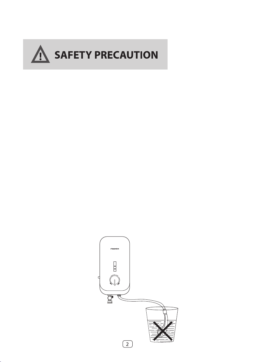
Faber SOTTILE SLIM Series User manual

FWH SOTTILE 306
FWH SOTTILE 307
FWH SOTTILE 308AC
FWH SOTTILE 309DC
INSTANT WATER HEATER
MODEL: SOTTILE SLIM SERIES
USER MANUAL
1

Thank you for purchasing FABER Instant Water Heater.
Please read this manual thoroughly and understands the content before use.
1. The appliance is not be used by persons (including children) with reduced physical
sensory or mental capabilities, or lack of experience and knowledge, unless they have
been given supervision or instruction concerning use of the appliance by aperson
responsible for their safety.
2. Children being supervised to ensure that they do not play with the appliance.
3. Do not install reverse INLET & OUTLET of heater.
4. Do not install the heater where there is consistent spray directly over the unit.
5. Do not connect the OUTLET to any tap or fitting that is not recommended by the
manufacturer.
6. Do not block the heater OUTLET in any way.
7. Do not attempt to repair the heater without qualified technician.
8. Do not leave children. elderly or disable person alone in shower.
9. Engage qualified electrician for installation.
10. Test water temperature with hand before using the shower.
11. Check the ELCB once a month (please refer to the RUN of Heater) and consult
professional for repair if there is any malfunction.
12. Metallic / chrome flexible hose and conductive control value shall not be used.
13. Do not leave the hand shower idle in the pail.
14. Use only new hoses to connect the appliance to the water supply. The old hose-sets
should not be reused.
15. This appliance is not to be used for portable water supply.

Terminal Block
Cable Entry
Booster Pump
Booster Pump Control Knob
Test & Reset
PCB
Water INLET
Connection
Water OUTLET
Connection
Heater Control Unit
Triac
Heater Tank
Thermal Cut Out
LED Display Board
ABS Heater Base
ELCB Control Board
ABS Front Cover
Power LED
Heater LED
Temperature
Control Knob
EXTERNAL PARTS IDENTIFICATION
INTERNAL PARTS IDENTIFICATION
LN

1. CHROME/ WHITE ACCESSORIES
G1/2
150mm Flexible Hose
Wall Bracket
Shower Holder
Hand Shower
Wall Bracket
Slider Railbar
SHOWER SET ACCESSORIES IDENTIFICATION

2. RAIN SHOWER SET
6
3
5 mm
6
5
0 mm
1
2
STEP 1
Water Saver Chip
A chip that helps you save water up to 50%!
ALERT
You may remove the two water saver chips if
prefer stronger water pressure. Please be
reminded that this is up to personal
preference.
STEP 2
Do marking for the location of the lower square and upper
round bracket. Install the bracket holders on the wall.
Assemble the upper tube with rain shower and lower tube
with divider.
Slide down and hook the assembled diverter to the
mounted square bracket.
Tighten the screws and make sure all joints are completely
connected to avoid leakage.
Rain Shower Head
360 Degrees 3-in-1 Rotation Diverter
360˚
180˚
90˚270˚
5
SHOWER SET ACCESSORIES IDENTIFICATION
There is two Water Saver Chips located
under the hand shower and on top of the
rain shower head.
Slide down
and hook
the
assembled
diverter to
the
mounted
square
bracket
Wall Bracket
Hand Shower
Diverter
Soap Dish
Silding Rail
Shower Holder
Water Saver
Chip
Water Saver
Chip
Tighten the
bottom screws

6
2
2. GENERAL INFORMATION
INSTALLATION
CAUTION:
THIS APPLIANCE MUST BE EARTHED
1. All the plumbing work should be completed before proceeding to electrical wiring connection.
(Table 1)
2. Installation must be carried out by a qualified electrician with close reference to the operation
manual and in compliance with the local regulations.
3. The unit works at minimum water flow rate of 2 litre/min, which then would trigger the bulit-in
pump (only for pump model), boostering a stronger shower spray.
4. The bulit-in electronic Earth Leakage Circuit Break (ELCB) would cut-off the power supply to
the heater in the event of current leakage of as low as 15mA.
5. The Thermal Cut-Off would automatically shut off the power supply shall there be any abnormal
rise of showering temperature.
6. The unit only operates when there is sufficient water flow to trigger the flow switch.
7. Electrical loading Table 1:
8. Instantaneous water heater’s shall be equipped with a 2 pole control switch and is own residual
current device.
9. Water heaters exceeding 3kW shall be permanently connected to a 20A/30A rated circuit breaker
/ fuse with an isolator switch and residual current device.

7
SAFETY PRECAUTION
Do not install reverse INLET and OUTLET of heater
Diagram 3
Stop Valve
Inlet
Outlet
correct installation inlet - outlet reverse
(wrong installation)
stop
valve
stop
valve
stop valve reverse
(wrong installation)
Inlet
Outlet Inlet Outlet
incoming
water OUTLET
INLET
stopvalve
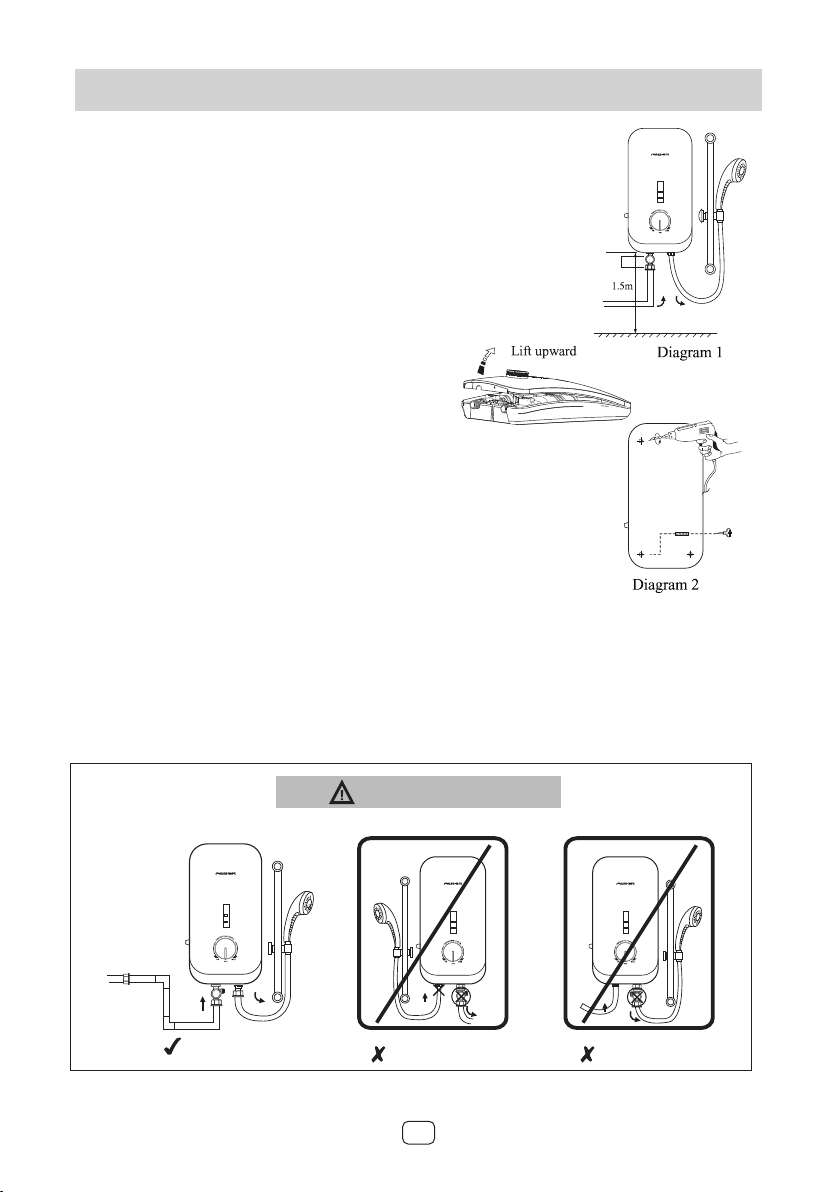
3. INSTALLATION PROCEDURES
1. All the plumbing works should be completed
before proceeding to electrical wiring connection.
2. INLET and OUTLET connection of the heater unit
should not be reversed, with stop valve installed on
INLET. (Diagram 1)
3. It is recommended that the unit should be mounted
above 1.5m or 5-feet above the floor to bottom of
the heater. (Diagram 1)
4. Mark mounting position (Diagram 2)
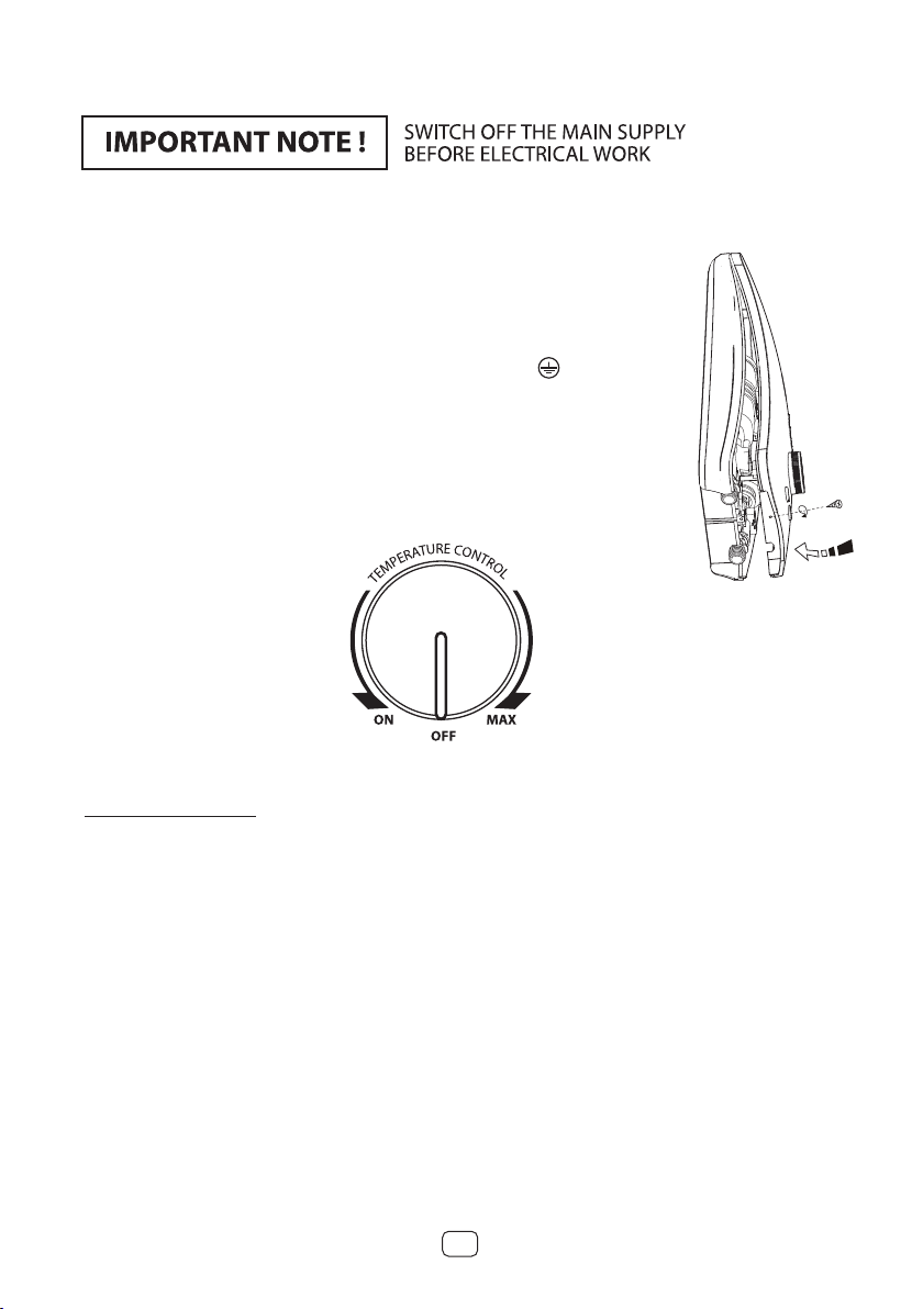
• Remove screw at the bottom of the heater
• Lift the plastic cover upward
• Mark mounting position on the wall
• Drill the holes with 5.0mm diameter drill bit
• Install the unit to the wall with plug
5. Heater INLET and OUTLET Connection (Diagram 3)
a) Connect the stop valve to INLET, and be sure to
put a gasket to prevent water leakage.
b) Connect the piping from the stop valve to incoming water supply. If necessary,
make use of sealing tape for the connection to prevent water leakage.
c) Connect flexible hose to heater OUTLET. Turn on the water mains to drain out all
the plumbing dirt and fill up the heater tank. Then, connect the flexible hole to the
hand shower.
(Note: This step will prevent damage to the heating element).

8
Restore cover
Diagram 4
STEP 2
STEP 1
Diagram 5
6. Electrical Connection
a) Insert electrical cable through the rubber
grommet as shown.
b) Connect the cable to the terminal block
and fully tighten them as the following:-
• Red or Brown........................................ Live (L)
• Black or Blue.......................................... Neutral (N)
• Green or Green/ Yellow....................... Earth
c) Restore the cover and secure screw at the bottom. (Diagram 4)
d) Align the knob, from ‘OFF’ position in clockwise direction
to‘MAX’and return to ‘OFF’ mark as shown (Diagram 5)
Test Run Of Heater:
a) Turn on the stop valve and water should spray out from shower head.
b) Switch on the main power supply (“POWER” LED would light up).
c) Turn on the Temperature Control Knob and ‘HEATER’ LED would light up.
The water should be warmed in a few seconds.
d) Turn on the Pump Control Knob to accelerate water flow.
(For Pump model only)
e) Test the ELCB by pressing ’TEST’ button. The unit should be tripped.
‘POWER’ and ‘HEATER’ LEDs would light off.
f) Press ‘RESET’ button, The unit should resume to normal condition.
g) The heater is now ready for use.

9
stop valve
Diagram 6
CLEAN
REGULARLY
4. OPERATION PROCEDURE
5. GENERAL MAINTENANCE
1. Switch on the main power supply, the ‘POWER’ LED would light up.
2. Turn on the water supply at the stop valve.
3. Turn on the Temperature Control Knob. The ‘HEATER’ LED would light up and the
water temperature will be increased accordingly as the knob being turned
clockwise from ‘ON’ to ‘MAX’.
4. For normal cold shower, just turn the Temperature Control Knob to ‘OFF’ position.
5. Switch off the power supply when not in use.
DO NOT USE THINNER, ALCOHOL OR PETROL
CLEAN FILTER REGULARLY (Diagram 6)
You may clean the heater with a damp cloth and mild detergent but do not use thinner,
alcohol, petrol or any other organic solution.
a) Remove the filter mesh at the stop valve (for filter type only) by turning the knob filter
counter clockwise direction and pull out the knob (Diagram 6). Flush it with water to
remove any trapped sediments. Install the knob filter back to its original position.

440(H) x 230(W) x 80(D)
Please refer Electrical loading Table 1
6 bar ( 0.6MPa / 87psi )
10
INVERTER SILENT PUMP (FWH SOTTILE 309DC)
3.6kW 240V 50/60Hz
Notes: The specification, actual product’s design and accessories parts shown are correct at the time
of printing and subject to change without prior notices.
6. TECHNICAL SPECIFICATION
7. SCHEMATIC WIRING DIAGRAM
Non Pump 1.4kg
Inverter Silent Pump1.9kg
AC Pump 2.2kg

11
AC PUMP (FWH SOTTILE 308AC)
NON -PUMP (FWH SOTTILE 306/307)

12
This manual suits for next models
4
Table of contents
Other Faber Water Heater manuals
Popular Water Heater manuals by other brands

Havells
Havells Rio operating instructions

Whale
Whale Expanse WL8212 operating instructions

Bradford White
Bradford White RG1PV50S Service manual

Graf
Graf one2clean installation manual

Danfoss
Danfoss Termix BTD RO MIX operating guide

Enviro Energy Solutions
Enviro Energy Solutions EBER Series Technical manual

Lochinvar
Lochinvar 000 - 300 User's information manual

andrews
andrews Flexistor 400 installation manual

Amtrol
Amtrol ST-1 Installation & operation instructions

Giona
Giona Style 10L 2kW Oversink Installation and service instructions

Rheem
Rheem Lazer Classic Series Owner's guide & installation instructions

Alpha
Alpha AST-30-V user manual