Falco Systems WMA-300 User manual

!
!
USER MANUAL
● High voltage: 50x amplification up to +150V and -150V output voltage
● DC to 5MHz (-3dB) large signal bandwidth and 300mA output current
● 2000V/µs slew rate typical
● No overshoot with capacitive loads: bandwidth changes automatically to
ensure stability
● Short-circuit protected output
About this manual
This user manual is an integral part of the
Falco Systems WMA-300 high voltage
amplifier product. Please read it carefully
and pay attention to the recommendations
and instructions for safe use.
The WMA-300 HV amplifier:
general description
The Falco Systems WMA-300 is a high
speed, high-voltage linear laboratory
amplifier for demanding applications. Its
wide bandwidth and large voltage range
make it an excellent choice for use with
MEMS devices, EO-modulators, piezo
positioning systems, beam steering,
ultrasonics, dielectric studies, and many
others.
Through the extensive use of computer
modelling and state-of-the-art design
concepts, this amplifier can be used in
many applications, including those where
conventional amplifiers are difficult to
apply. It is designed to be absolutely stable
and free of spurious signals with any
capacitive load.
The amplification is 50x (fixed). With a
range of –150V to +150V, a large signal
bandwidth of 5MHz @ -3dB and a typical
slew rate of 2000V/μs, this amplifier will
Falco Systems WMA-300 High Voltage Amplifier DC – 5MHz

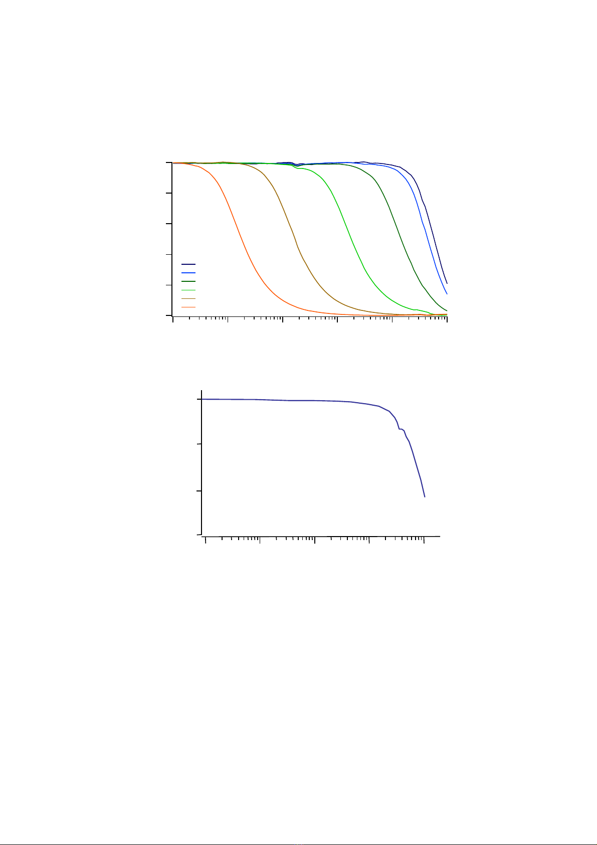
enable many measurements in different
applications. Its frequency response is
essentially flat up to 2MHz.
A fast current limit of ±300mA (typical) and
a fast short-circuit protection make this
amplifier suitable for both the normal daily
laboratory use, and for automated
measurement systems.
Safety
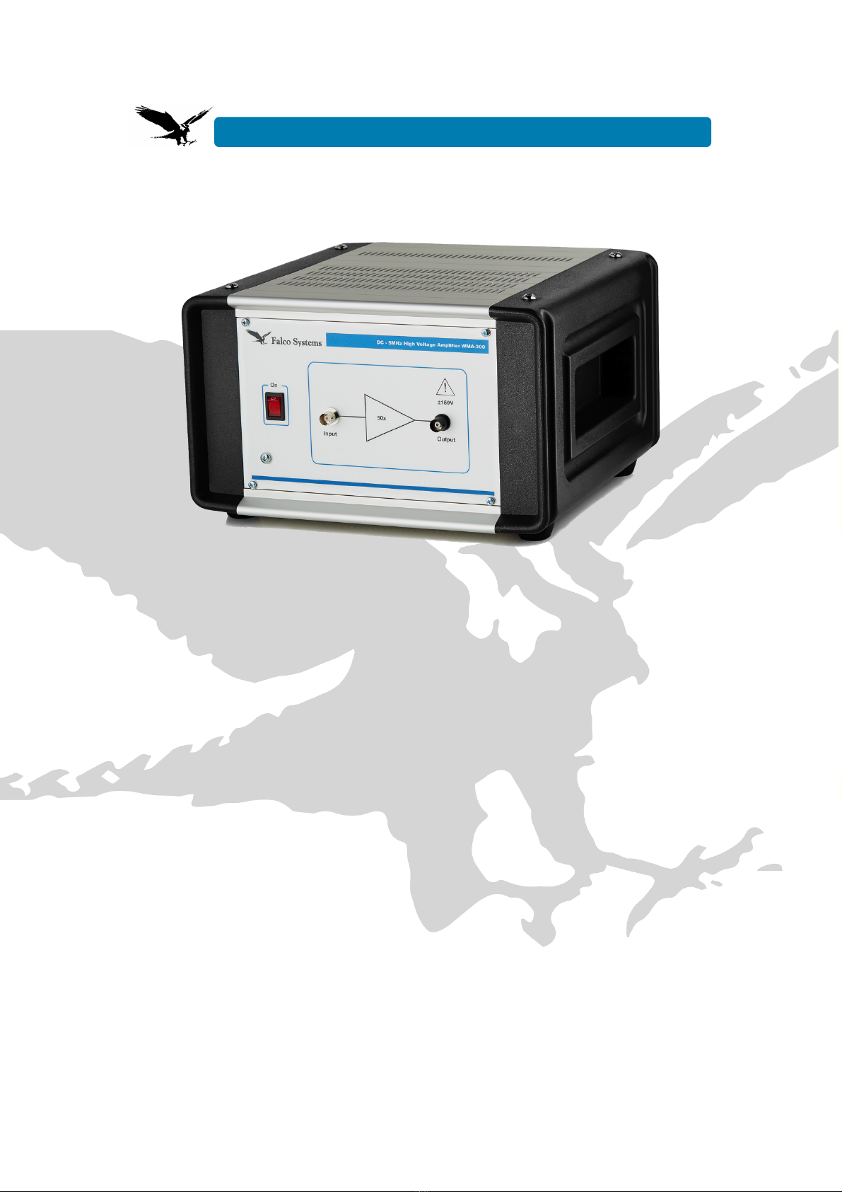
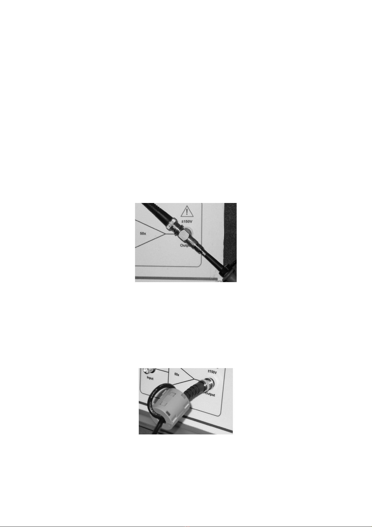
- This product is able to produce over 150V
at more than 300mA at its output, which is
a dangerously high level (risk of electric
shock). Safety measures should be taken
accordingly. This is indicated by the sign
above the output connector of the
amplifier.
- Only use this appliance with a mains
connection with protective earth
- The internal circuitry of the amplifier
operates at high voltage. Only qualified
personnel from Falco Systems should
service this amplifier.
- When the amplifier is turned on or off, a
short voltage spike may appear at the
output which may damage circuitry already
connected to it.
- Replace fuses with 250V 630mA 5x20mm
slow blow rated fuses only.
- The Falco Systems WMA-300 is only
suitable for indoor use in a class II
environment (domestic, light industrial).
- This product should only be cleaned with
a soft, slightly moist cloth. Unplug the
WMA-300 from the mains power before
cleaning.
Detailed properties of the WMA-
300 high voltage amplifier
Input protection
A high-speed amplifier like the WMA-300
can never be made fully insensitive to
input overload conditions, as this would
limit the performance of the amplifier to an
unacceptably low level. However,
compared to other circuits, the input is
protected extremely well by a combination
of a high-power 50Ω impedance and diode
protection for extreme overload conditions.
It can even withstand connecting the
output to the input for some time, which
may accidentally happen in a lab when
cables are going everywhere.
For normal operation, input voltages
should remain in the -3V to +3V range,
resulting with an amplification of 50x in an
output voltage swing of -150V to +150V.
Above 3V (-3V), the input protection
diodes will limit the voltage fed to the
amplifier.
Above 30V (-30V) at the input, the
amplifier may be permanently damaged if
the current of the source is not limited. The
output can be connected to the input
because the current limit of the amplifier
will cut back the voltage to a level that can
be managed by the input.
Never apply more than +30V (-30V) to the
amplifier input!
Output protection
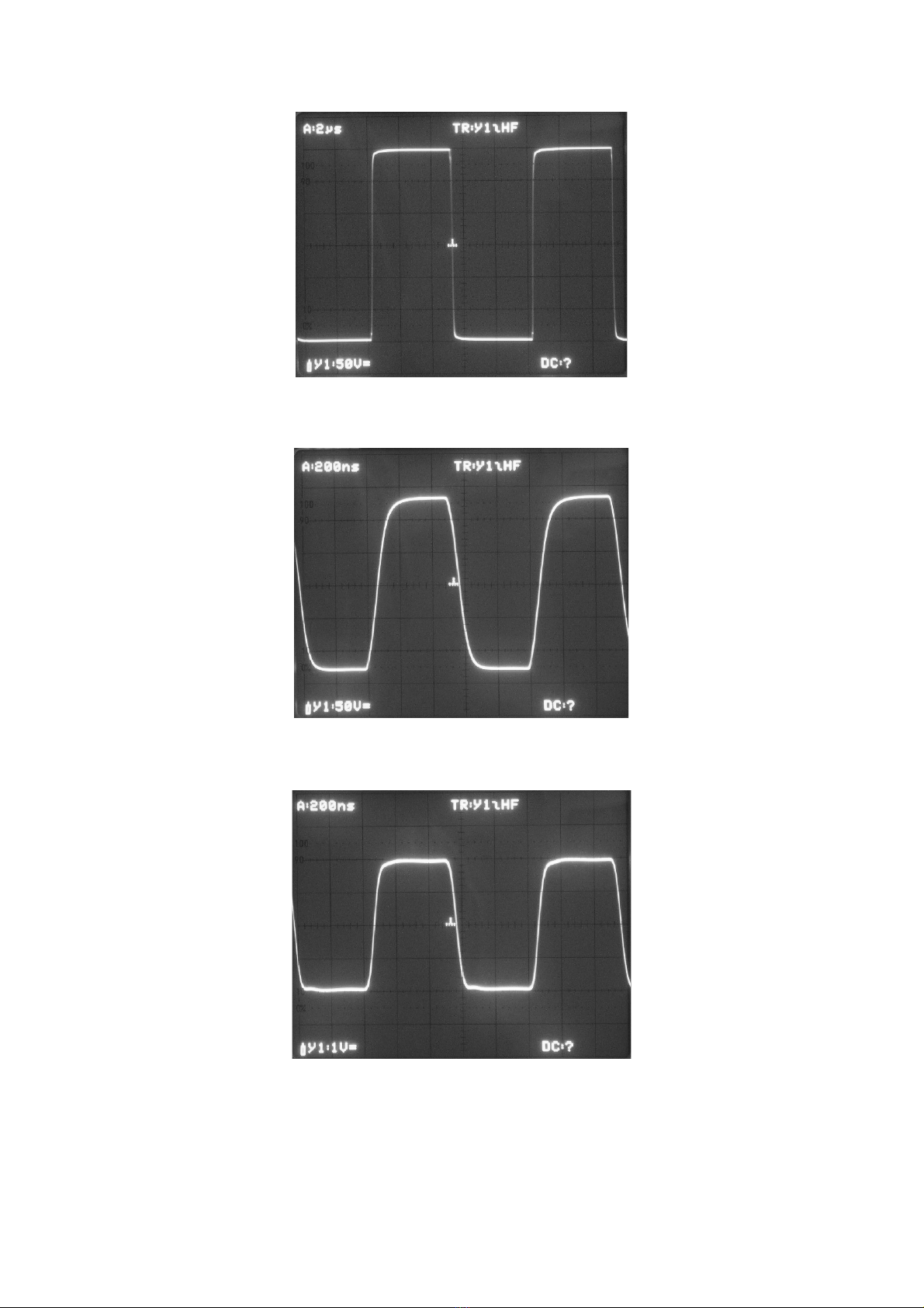
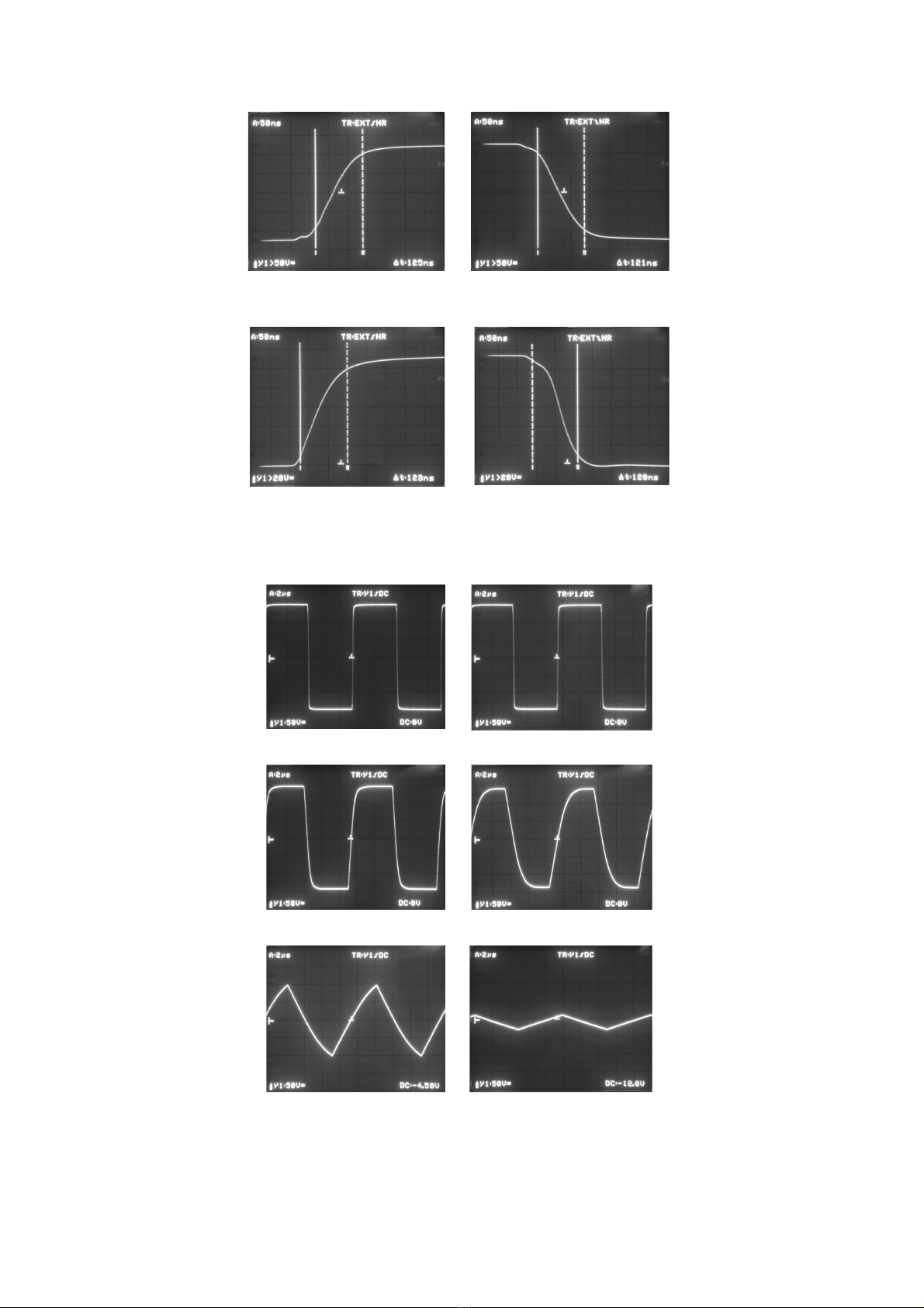
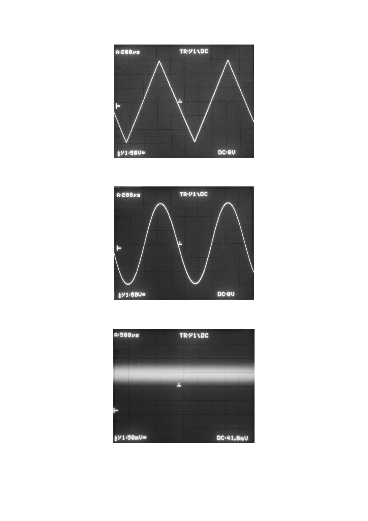
The WMA-300 has been designed to be
fully stable with all capacitive loads. It has
been optimized for its step-response, but is
also a very good linear and sine-wave
amplifier.
Instability under capacitive loading
conditions is a common problem of high-
speed negative feedback amplifiers on the
market, often resulting in unwanted
overshoot voltages, and, in extreme cases,
oscillations (check the respective manuals
and datasheets for details). In the WMA-
300, this problem has been solved by a
clever dual feedback system. No significant
overshoot occurs at any capacitive load.
Overloading or short-circuiting this amplifier
will not break down the amplifier, due to the
extremely fast current limiting circuit that
has been employed.
Although the amplifier cannot be damaged
by a short-circuit condition or capacitive
loading, two situations should be avoided:
- Connecting a charged capacitor
- Using high inductance values (coils)

The load
The output impedance of the WMA-300 is
50Ω. The amplifier is generally used for
high-impedance applications where the
load is mainly capacitive. This is true for
MEMS devices, EO-modulators and PZT's
(piezo’s) alike. It should be noted that a
coaxial cable also presents a capacitive
load of approximately 100pF/m. The cables
that are connected may well limit the
maximum usable current at high
frequencies.
Matched loading with a 50Ω circuit is
possible by connecting a 50Ω resistor in
series with the output to ground, but is not
usually recommended. The advantage is
that excessively long cables will not distort
the waveforms anymore. The disadvantage
is a clearly reduced voltage range (300mA
in 50Ω gives 15V instead of 150V).
With high-frequency measurements, cable
length should be minimized or the cables
themselves will cause overshoot and
current limiting. Although the amplifier
remains fully stable, more than 1.5 meter of
output cable is not recommended for the
WMA-300 for optimal results.
If output monitoring is required, it is
recommended to connect a 10x
oscilloscope probe to the output. A special
BNC to probe tip connector is usually
supplied with the probe (Fig. 1). However,
the user can choose a different way of
connecting the oscilloscope, as long as
care is taken with the high output voltage.
Pieces of non-coaxial cable in the
connection can cause overshoot in the
oscilloscope reading.
Figure 1. The 10x probe connected for monitoring the output signal
The amplifier should not be used for
telecommunication as described in the
R&TTE directive 95/5/EC. To prevent
unwanted radio emission, the TDK ferrite
ring which is supplied with the instrument
should be mounted on the output cable
close to the WMA-300 housing as
indicated in Fig. 2, when square wave
output signals above 100kHz and 50V are
generated. In this case, the length of the
output cable should be no more than 1.5
meter. The measurement is not influenced
by this ring; it is only required to comply with
European EMC legislation.
Figure 2. The ferrite ring (type TDK ZCAT3035-1330) should be placed on the output cable as
indicated when a square wave of more than 100kHz and 50V is generated to prevent
unwanted radio emission in the 30MHz region.

!
!
Amplifier characteristics
In the following pages, several amplifier
characteristics are shown:
- Frequency response (Fig. 3, 4)
- Square wave response (Fig. 5, 6, 7)
- Slew rate (Fig. 8)
- Capacitive load dependency of square
wave output (Fig. 9)
- Triangle and sine response (Fig. 10, 11)
- Noise and offset (Fig. 12)
- Input to output delay time (Fig. 13)
Figure 3. Frequency response at 300Vpp output voltage
Figure 4. Frequency response with no load at 3Vpp output voltage
Frequency (Hz)
50
40
30
20
10
0
102103104105106107
0pF
100pF
1nF
10nF
100nF
1uF
Amplification factor
Output amplitude (Volt)
103104105106107
Frequency (Hz)
0
1
2
3

Figure 5. 300Vpp 100kHz square wave
Figure 6. Full scale 1MHz square wave
Figure 7. 4Vpp small signal 1MHz square wave

Figure 8. Slew rate (definition: step response from 10% to 90% signal). 240V in 125ns ≈
2000V/μs
Figure 9. Full-power 100kHz square wave response with different capacitive loading
conditions. The 300mA current limit limits the speed at which the capacitor can be charged.
300Vpp step up in 125ns
300Vpp step down in
121ns
0V to 150V in 123ns
150V to 0V in 120ns
300Vpp step up in 125ns
300Vpp step down in
121ns
0V to 150V in 123ns
150V to 0V in 120ns
0pF
150pF
1.5nF
4.7nF
15nF
82nF

Figure 10. Triangle wave 300Vpp 1kHz
Figure 11. Sine wave 300Vpp 1kHz
Figure 12. Noise (about 70mVpp or, equivalently, 12mV rms) and typical offset. The offset
may shift during high-power, high frequency operation due to temperature gradients between
different parts of the circuit

Figure 13. Input to output delay time = 140ns
Technical specifications
Amplification: 50x, fixed
Bandwidth: DC – 5MHz @ -3dB large signal bandwidth
Slew rate: 2000V/μs typical
Output voltage: -150V to +150V
Current: 300mA typical with limiter
Noise and offset: 12mVrms output noise over the full bandwidth typical, 100mV offset typical
Input impedance: 50Ω
Output impedance: 50Ω
Stability: stable with all capacitive and resistive loads, no overshoot > 5%
Power: 230V 50Hz AC, 120W
Mains fuse: 2x 0.63A 250V slow blow
Safety: Class I - requires mains power connector with protective earth
Overvoltage: Category II
Operating temperature: 15 – 30°C
Storage temperature: 0 – 60°C
Relative humidity: 30 – 70% non-condensing
Maximum usage height: 2000m
Dimensions: 280 x 280 x 160mm
Weight: 6.8kg
Country of origin: The Netherlands
Specifications may be subject to change

Harmonized standards
This product complies with the following
harmonized European standards:
Safety: EN61010-1
EMC: EN61326
WEEE and RoHS
Do not dispose of the WMA-300 amplifier
as standard waste, but bring it to a WEEE
electronic waste collection point. The
amplifier has been built in compliance with
the RoHS directive.
Warranty
Falco Systems products are guaranteed
against malfunction due to defects in
materials or workmanship for a period of 1
year from the date of shipment.
If a malfunction occurs during this period,
the product will be repaired or replaced
without charge. The product will be
returned to the customer prepaid.
The warranty does not apply to:
- Exterior finish or appearance
- Malfunction resulting from use or ope-
ration of the product in other ways than
specified in the user manual
- Malfunctioning due to misuse or abuse of
the product
- Malfunctioning occurring after changes or
repairs have been made by anyone other
than Falco Systems.
To obtain warranty service, the customer
has to inform Falco Systems first via
info@falco-systems.com to receive further
instructions.
Falco Systems will not be liable for any
consequential damages, including, without
limitation, devices or equipment connected
to the product, injury to persons or property
or loss of use. See for more details the
Falco Systems Standard Terms and
Conditions of Sale, which can also be
obtained via info@falco-systems.com.
User manual version
User manual version: 2.4
Date: July 2019
Falco Systems
Falco Systems
Remisestraat 1
2225 TH Katwijk aan Zee
Tel. +31 (0)6 21840996
Fax. +31 (0)20 2031 445
Email: info@falco-systems.com
http://www.falco-systems.com
Other manuals for WMA-300
1
Table of contents
Other Falco Systems Amplifier manuals

Falco Systems
Falco Systems WMA-02 User manual

Falco Systems
Falco Systems WMA-02 User manual

Falco Systems
Falco Systems WMA-100 User manual

Falco Systems
Falco Systems WMA-005 User manual

Falco Systems
Falco Systems WMA-005 User manual

Falco Systems
Falco Systems WMA-300 User manual

Falco Systems
Falco Systems WMA-100A User manual

Falco Systems
Falco Systems WMA-200 User manual

Falco Systems
Falco Systems WMA-280 User manual

Falco Systems
Falco Systems WMA-100 User manual