5
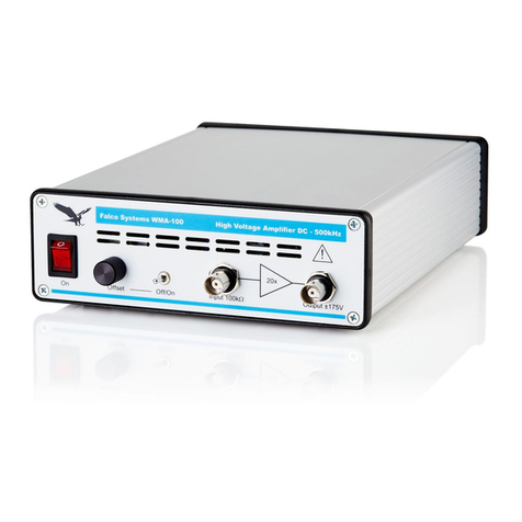
Detailed properties of the WMA-100 high voltage amplier
Input
The input impedance of the WMA-100 high voltage amplier is a 100kΩ resistor
to ground, in parallel with 68pF to prevent electrostatic discharge (ESD) input
damage. This resistor adds some noise to the output voltage unless a low-impe-
dance source (e.g. a 50Ω output function generator) is connected to the input.
The noise will be slightly higher when the amplier input is left open.
The 100kΩ resistor also adds to the output offset voltage because the offset
current of the input amplier generates a voltage over this resistor. This output
offset voltage is ~10mV if the input is left open. When the input is shorted or
connected to a low-impedance source, the offset is reduced to ~8mV.
A high-speed amplier like the WMA-100 model can never be made fully
insensitive to input overload conditions, as this would limit the performance of
the amplier signicantly. For normal operation, input voltages should remain
in the –8.75V to +8.75V range, resulting, with an amplication of 20x, in an
output voltage swing of –175V to +175V. Below -15V and above +15V, the input
protection circuitry will limit the voltage fed to the amplier, but the amplier may
be permanently damaged if the current of the source is not limited.
Output
The WMA-100 model has been designed to be fully stable with all capacitive
loads. It has been optimized for a perfect step-response, but it is also a very
good linear and sine-wave amplier.
The WMA-100 amplier has a clever feedback system, which ensures that
no signicant overshoot occurs at any capacitive load. The bandwidth of the
amplier is automatically reduced to ensure stability. Instability under capacitive
loading conditions is a common
problem of other high-speed negative feedback ampliers, often resulting in
unwanted output overshoot voltages, and, in extreme cases, oscillations.
Short-circuiting this amplier will not break down the amplier, due to the extre-
mely fast current limiting circuit that has been employed.
If output monitoring is required, it is recommended to connect a 10x oscil-
loscope probe to the output. A special BNC to probe tip connector is usually
supplied with the probe (Fig. 1). However, the user can choose a different way
of connecting the oscilloscope, as long as care is taken with the high output vol-
tage. Using non-coaxial cable can cause overshoot in the oscilloscope reading.
