manuals.online logo
Brands
  1. Home
  2. •
  3. Brands
  4. •
  5. Falcon
  6. •
  7. UPS
  8. •
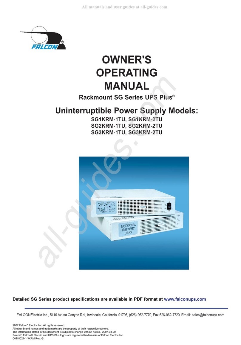
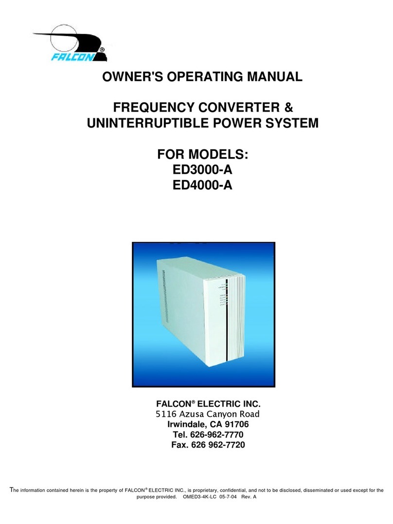
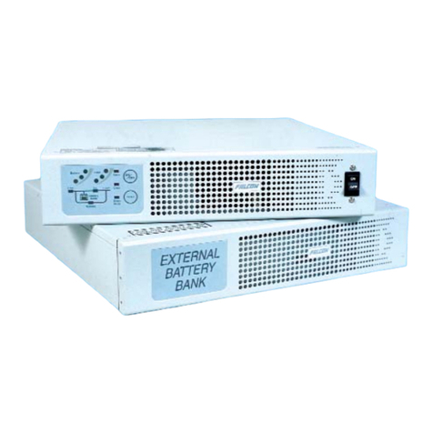
  9. Falcon SSG6KRM-2 Instruction Manual

Falcon SSG6KRM-2 Instruction Manual

© 2022 Falcon® Electric, Inc. All rights reserved. Falcon® and the Falcon Electric logo are registered trademarks of Falcon Electric, Inc.
All other brand names and trademarks are the property of their respective owners. The information and specifications stated in this document
are subject to change without notice. OM480064 Rev. A, 6-2022
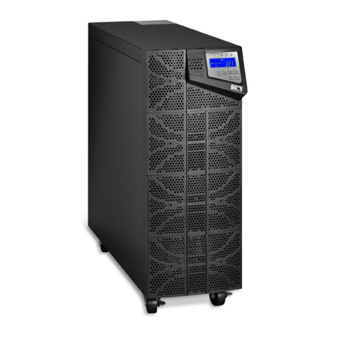
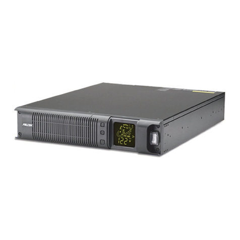
SSG Industrial UPS (Wide-temperature)
Installation & User Manual
6kVA
SSG6KRM-2
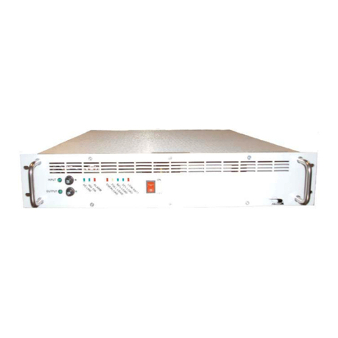
XM6KRM-2/2
SSGR
2
3
Contents
INTRODUCTION ......................................................................................................................................4
Manual Overview...................................................................................................................................4
UPS Features........................................................................................................................................4
SAFETY....................................................................................................................................................6
PRODUCT OVERVIEW............................................................................................................................8
Operating Conditions.............................................................................................................................8
UPS Circuit Descriptions.......................................................................................................................9
Inspecting the Equipment....................................................................................................................10
Box Contents.......................................................................................................................................11
UPS Overview.....................................................................................................................................13
UPS Component Overview .................................................................................................................16
Display & Controls ..................................................................................................................................17
Getting Started........................................................................................................................................19
Installation Environment......................................................................................................................19
Rackmount Installation........................................................................................................................20
Battery Bank Installation......................................................................................................................23
Electrical Wiring...................................................................................................................................24
Output Configurations .........................................................................................................................26
UPS Start-up Procedure......................................................................................................................28
UPS Operation........................................................................................................................................30
Operating Modes.................................................................................................................................30
Communications .....................................................................................................................................36
Communication Features ....................................................................................................................36
Dry Contact Relay Cards.....................................................................................................................37
Batteries..................................................................................................................................................39
Safety ..................................................................................................................................................39
Battery Information..............................................................................................................................40
Battery Pack Replacement..................................................................................................................42
Troubleshooting ......................................................................................................................................43
Alarms .................................................................................................................................................43
Technical Support...................................................................................................................................46
Contact Us ..........................................................................................................................................46
Warranty .................................................................................................................................................47
4
INTRODUCTION
Manual Overview
This user manual provides basic information about the Falcon SSG Industrial Wide-temperature
Uninterruptible Power Supply (UPS). This SSG model is available in nominal power rating of 6000 volt-
amperes (VA).
This manual also provides complete unit installation, safety considerations, important features, as well
as detailed operation, configuration and troubleshooting of this device.
UPS Features
-20°C to 55°C temperature range
The SSG UPS is agency-certified (UL, cUL,
CE) to operate reliably in demanding
environments.
Long-life UPS: true on-line, industrial
Tested and designed with robust components
and materials, the SSG assures reliable
operation and a long service life in stressful
environments. It is a true on-line industrial UPS.
12-year rated batteries cut service costs
The long-life batteries cut frequent battery
replacements and maintenance costs. They
have a 12-year life at 25°C and 4 years at 50°C.
Extended battery banks
The battery banks are easily expandable to
provide minutes to hours of extra battery
runtime.
Available options / Advanced
communications
NEMA 3R-rated enclosures, environmental
protection, remote UPS management,
environment sensors, relay cards – and much
more.
Falcon – recognized for quality and
reliability
Falcon Electric is a recognized authority in
industrial UPS solutions. Our technical
expertise assures you find the right solution –
the first time.
5
Double Conversion On-line UPS Block Diagram
6
SAFETY
Retain This User Manual
SAVE THESE INSTRUCTIONS - This manual contains important instructions that should be followed
during installation and maintenance of the UPS and batteries.
Please read all instructions before operating the equipment and save this manual for future reference.
All the models presented herein are designed for installation and use in a protected environment, free
of contamination.
This UPS operates from utility power and contains several high current batteries; this information is
important to all personnel involved. Please read this manual first before continuing to unpack, install or
operate this UPS.
Warnings
CAUTION: Risk of electric shock. Do not remove cover. No user serviceable parts inside. Refer
servicing to qualified service personnel.
CAUTION - Risk of Electric Shock - Battery circuit is not isolated from AC input; hazardous voltage may
exist between battery terminals and ground. Test before touching.
WARNING: To reduce the risk of fire or electrical shock, replace only with the same type and rating of
fuse.
CAUTION - To reduce the risk of fire, connect only to a circuit provided with 30 amperes maximum
branch circuit overcurrent protection in accordance with the National Electric Code, ANSI/NFPA 70.
(U.S. Installations only.)
Adhere to all local and national electrical codes.
This UPS should be installed according to the instructions in this manual. Failure to do so could result
in unsafe operation and could invalidate your warranty.
This device is not intended for life support applications.
The maximum UPS output load (in watts) must never exceed that shown on the UPS rating label.
Do not connect inductive load type equipment that could severely overload the UPS including but not
limited to motors, pumps, vacuums, or high voltage contactor coils.
The UPS, battery packs and battery banks are heavy. Take proper precautions when lifting or moving
them.
If using an external maintenance bypass switch, assure the UPS is manually placed in bypass mode
before operating the maintenance bypass switch. Failure to follow this procedure will result in damage
to this device.
7
Symbols
Important Instruction
Special Note
Recycle
Do not dispose with ordinary trash
8
PRODUCT OVERVIEW
Transportation
The UPS must be handled with care and given special attention due to the high amount of energy
stored within its internal sealed, lead-acid batteries. Please retain the shipping containers in the unlikely
event the UPS need to be returned for service. The containers have been specifically designed to ship
the UPS system safely.
Operating Conditions
This UPS must be installed in a protected environment, free from moisture, flammable gases or fumes
and corrosive substances.
Operate the UPS in a protected environment within the temperature range of -20ºC to 55ºC (-4ºF to
131ºF). A temperature of 0°C to 40°C (32°F to 104°F) will maximize the battery life which is rated at 12
years at 25°C (77°F). This UPS is designed for use with industrial, scientific or data processing class
equipment.
The SSG Industrial UPS requires minimal maintenance or monitoring if the documented installation,
environmental and operational specifications have been met. The items provided below are basic
preventative maintenance measures to maintain UPS service life:
Cooling Fans:
oAssure the cooling fan guards / vents are free of dirt / dust build up every 6 to 12
months depending on environment. The UPS vents are located on the rear and / or
front panel of the UPS.
Ambient Temperature:
oMonitor ambient temperature to ensure it is within the UPS specification. This is
critical to maintain maximum battery life.
Batteries:
oTo maintain optimum battery life, the user should operate the UPS in an ambient
temperature of 25ºC to 30ºC (77ºF to 86ºF). At higher temperatures, battery life will
be significantly reduced.
oAs the ambient temperature rises, monitor the battery capacity by performing a
battery self-test every 6 to 12 months.
9
UPS Circuit Descriptions
Input Filter
This circuit filters out both electro-magnetic interference (EMI) and radio frequency interference (RFI)
and prevents excessive levels from being conducted back to the utility source. All SSG models have
been tested and comply with FCC Class A requirements.
Input Rectifier & Power Factor Correction
While the UPS is operating from the utility source, this circuit converts utility AC power to regulated DC
power for inverter use. It corrects the input current to maintain a sinusoidal waveform to minimize the
amount of current distortion that will be reflected to the utility.
DC/DC Converter
The DC/DC converter utilizes energy from batteries and boosts up the DC bus voltage to a level
required by the inverter. This allows the inverter to operate continuously at optimum efficiency and
voltage. The converter incorporates a circuit which reduces the amount of ripple current and EMI
interference to the battery, increasing the overall battery life.
DC/AC Inverter
In utility mode operation, the inverter utilizes the regulated DC output to invert DC back into clean,
regulated AC power. When utility power fails, the inverter will receive its energy from the battery
through the DC/DC converter. In both modes of operation, the UPS inverter is online and continuously
generating clean, regulated AC power to the load. The Isolated Gate Bipolar Transistor (IGBT), Pulse
Width Modulation (PWM) inverter design produces a pure sine wave output with a +/-2% voltage
regulation.
Hot-swappable Battery Packs
The SSG UPS utilizes a flame-retardant battery pack comprised of four 12V, 7AH, valve-regulated,
sealed lead acid (VRLA) batteries in each pack. The battery packs are interchangeable between all
SSG 1.5kVA to 6kVA rackmount models. They are easily replaced through the UPS or battery bank
front panel. Optional extended battery banks are available from Falcon.
Battery Charger
The battery charger utilizes energy from the utility power source to continuously charge the UPS
batteries. The UPS batteries are being charged whenever the UPS is plugged in, turned on and
operating from utility power. The internal UPS battery charger output is rated at 1 amp.
Manual Bypass Function
A manual bypass button is located on the SSG front panel. When the UPS is operating from utility
power in online mode, depressing this button will cause the UPS to transfer to bypass. The bypass
condition transfers the connected equipment to the utility power source via an internal relay. During
bypass condition, the UPS inverter and battery backup operation is disabled. Depressing the bypass
button again will return the UPS to online mode.
10
Automatic Bypass Function
The SSG UPS will automatically switch to bypass to energize the connected load when the UPS is first
turned on, encounters an overload, over temperature condition, or failure condition. Should any of these
events occur, the UPS will transfer to bypass mode, sound an audible alarm, and provide a bypass
indication on the LCD display. The output filter and the input filter stage maintain the conducted EMI
and RFI levels below FCC Class A limits.
Maintenance Bypass Switch (MBS)
A maintenance bypass switch is located on the optional XM6KRM-2/2 transformer box. This switch
serves to provide power to the connected equipment in case of UPS failure or maintenance is required.
Inspecting the Equipment
Visually inspect the UPS for shipping damage. If the equipment has been damaged during shipment,
and is signed for as received, make sure the receiver slip is noted with the detail of the damage
exception. Keep the shipping cartons and packing materials for the carrier, and immediately file a claim
for “shipping damage” with the carrier. If you discover damage after acceptance, file a claim for
“concealed damage.”
To file a claim for shipping damage or concealed damage:
You must file with the carrier within 24 hours of receipt of the equipment.
You must send a copy of the damage claim within 3 days to Falcon Electric, Inc.
11
Box Contents
The UPS is shipped complete with all cables and accessories required for operation. A full listing of the
box contents is provided below:
SSG6KRM-2 Inverter:
XM6KRM-2/2 Transformer:
12
SSGR / SSGR-1, -2 Models:
13
UPS Overview
UPS Inverter: SSG6KRM-2
Front View
A: Function / Test Button
B: Set / Alarm Silence Button
C: Power / Bypass Button
D: LCD Display
UPS Transformer: XM6KRM-2/2
Front / MBS View
M: Removeable front panel N: Maintenance Bypass Switch
A DB
C
M
N
14
SSG6KRM-2
Rear View
E: Input Terminal Block
F: Input Circuit Breaker
G: Output Terminal Block
H: Communication Option Slot
I: Battery Connectors
J: Battery Fuses
K: DB-9, RS232
L: Remote Emergency Power Off (R.E.P.O)
Terminal
XM6KRM-2/2
Rear View
O: Cooling Fans
P: Utility Input
Q: UPS Inverter Output
R: System Output (User Configurable)
FE G H I
L
K
J
O
P Q R
15
SSGR
Rear View
1: Battery Circuit Breaker
2: Additional Battery Connection
3: Battery Connection
SSGR-1 / SSGR-2
Rear View
4: Battery Circuit Breaker
5: Additional Battery Connection
6: Battery Connection
7: AC Power Switch
8: AC Power Cord Inlet with Fuse (3A / 250V)
9: Daisy Chain Inlet (3A Max)
1 2 3
4 5 6
7 8 9
16
UPS Component Overview
AC Terminal Block: Hardwired terminal block
for input, output and transformer
interconnections to UPS Inverter.
Battery Pack Compartment: Compartment
housing the 48V battery pack for the SSGR
models. The front panel and support bracket
must be removed to expose compartment.
Battery Fuse: These protection devices are
required for proper UPS operation and
protection against over-current condition.
Battery Circuit Breaker: This protection device
is used to disconnect the battery voltage from
the UPS inverter module.
Input Circuit Breaker: One or more protection
devices provided to protect the UPS input from
an over-current condition.
Cooling Fan: One or more devices provided to
maintain the proper temperature of the internal
electronics.
Battery Connection: When the cover plate is
removed, this universal port is exposed to allow
connection of an SSGR battery bank.
REPO Interface: Remote Emergency Power
Off provides an interface for a NFPA 70, NEC
645-11 compliant shut off closed loop switch.
Communication Option Slot: When the cover
plate is removed, a card slot is available for
options, i.e., SNMP / HTTP Web Interface &
Dry Contact Relay Cards.
RS-232 Connector DB-9F Port or USB Port:
Two connectors provided to access the
system’s RS-232 protocol.
17
Display & Controls
LCD Display
The diagram to the right shows all available icons of the front
panel LCD for all SSG models. Refer to the LCD symbols in the
left-hand column, below for their functional definition:
Utility Power Status: Line cord icon indicates utility
power is within specification.
PFC Status: Sine wave icon indicates the input power
factor correction (PFC) is functioning properly.
Inverter Status: Generator icon indicates the inverter is
functioning properly.
Charger Status: Gas pump icon indicates the charger is functioning properly.
Output Load %: The greater the load, up to three vertical bars will be illuminated at the top of
the weightlifter icon. Each bar represents approximately 25% of the UPS output rating.
Battery Mode: Scissor lift icon indicates the UPS is in battery mode.
Battery Level: Battery cell icon indicates the battery capacity. The greater the battery capacity
available, the more internal bars will be illuminated. Each bar represents 25% capacity.
Fan in high-speed mode: HS fan icon indicates fans are in high-speed mode.
Fan in medium speed mode: MS fan icon indicates fans are in medium speed mode.
Fan in low-speed mode: LS fan icon indicates fans are in low speed mode.
BIT Window: The bit window displays programmable settings and fault condition error codes.
Audible Alarm: Speaker icon indicates the audible alarm is on.
Test: Test icon flashes indicating a battery self-test is being performed.
UPS Fault Condition: Exclamation point icon indicates an alarm condition exists.
Green Mode: Bulb icon indicates the green mode function is enabled. It will flash when the UPS
has switched to green mode due to the UPS output load decreasing to less than 3% of the total
UPS output rating.
Metering: Seven segment display provides readings for voltage, current, temperature, applied
load and frequency reported from the UPS.
18
Front Panel Controls
Function / Test Button: Multifunctional key performs the battery self-test and is used to scroll
through bit options during UPS function setting.
Set / Alarm Silence Button: Multifunctional key disables audible alarm, used to scroll through
metered parameters and sets the desired programmed setting.
Power / Bypass Button: Multifunctional key performs DC cold start to power UPS without utility
power present, places UPS into bypass mode and is used to turn off UPS when utility power is
lost.
19
Getting Started
Installation Environment
The UPS can be installed as a standalone tower or rack mounted in a typical 19” equipment rack. Each
UPS inverter and transformer module requires 4U (7” / 178mm) of vertical rack space.
Do not block air flow.
Allow a minimum of 3 inches / 76.2mm clearance from the front and rear panel air vents.
Environment:
oIntended for use in a protected environment, free from moisture, flammable gases or
fumes and corrosive substances.
oAmbient Temperature:
Ideal: 25ºC to 30ºC (77ºF to 86ºF)
Maximum: -20ºC to 55ºC (-4ºF to 131ºF)
oHumidity:
10-95% (non-condensing)
Airflow Direction
DO NOT BLOCK DO NOT BLOCK
20
Rackmount Installation
Securing hardware, slide rails (SGRMKIT) and rail extensions (DP70357) are sold separately.
The UPS is designed to fit in a 19” equipment rack. Each UPS inverter and transformer module
requires 4U (7 inches / 178mm) of vertical rack space.
The supplied rack mounting ears are intended to secure the units to the rack rails. They do not
support the weight of the UPS, transformer or battery bank. Rack slides or shelves are required.
Reference the following procedure to install the UPS in a standard 19” equipment rack:
1. Place the UPS on a flat, stable surface with either side of the UPS facing you.
2. Align mounting ears with screw holes on each side of the UPS and secure with the supplied
screws. (12) M4 x 6mm.
a. Repeat the procedure for the transformer module or battery banks to be used.
(6) M4 x 6mm
Each Side

This manual suits for next models

4

Other Falcon UPS manuals

Falcon SSG1.5KRM-1 Operation manual

Falcon

Falcon SSG1.5KRM-1 Operation manual

Falcon MLP-300-1 User manual

Falcon

Falcon MLP-300-1 User manual

Falcon ED3000-A Operation manual

Falcon

Falcon ED3000-A Operation manual

Falcon SG800-1, SG800-2 SG1K-1T, SG1K-2T SG2K-1T Use and care manual

Falcon

Falcon SG800-1, SG800-2 SG1K-1T, SG1K-2T SG2K-1T Use and care manual

Falcon SG5K-1TX Use and care manual

Falcon

Falcon SG5K-1TX Use and care manual

Falcon SG5K-1TX Operation manual

Falcon

Falcon SG5K-1TX Operation manual

Falcon XG1.5K-1T Operation manual

Falcon

Falcon XG1.5K-1T Operation manual

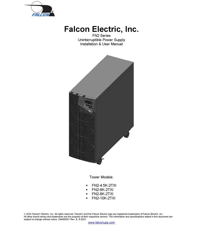
Falcon FN2-4.5K-2TXI Instruction Manual

Falcon

Falcon FN2-4.5K-2TXI Instruction Manual

Falcon ED Series Operation manual

Falcon

Falcon ED Series Operation manual

Falcon ED-1000-1 User manual

Falcon

Falcon ED-1000-1 User manual

Falcon ED-1000-1 User manual

Falcon

Falcon ED-1000-1 User manual

Falcon USHA IX900 Series User manual

Falcon

Falcon USHA IX900 Series User manual

Falcon UPS Plus SG Series Operation manual

Falcon

Falcon UPS Plus SG Series Operation manual

Falcon SSG500VA-1 Operation manual

Falcon

Falcon SSG500VA-1 Operation manual

Falcon SG1KRM-1TU Operation manual

Falcon

Falcon SG1KRM-1TU Operation manual

Falcon SG800-1T Operation manual

Falcon

Falcon SG800-1T Operation manual

Falcon SG2K-X1T Operation manual

Falcon

Falcon SG2K-X1T Operation manual

Falcon FN3K-2TXI Operation manual

Falcon

Falcon FN3K-2TXI Operation manual

Falcon UNINTERRUPTIBLE POWER SUPPLY MODELS SG1K-2T User manual

Falcon

Falcon UNINTERRUPTIBLE POWER SUPPLY MODELS SG1K-2T User manual

Falcon SSG1.5KRM-2 Instruction Manual

Falcon

Falcon SSG1.5KRM-2 Instruction Manual

Falcon FN2 Series Instruction Manual

Falcon

Falcon FN2 Series Instruction Manual

Falcon ED1000RM-1 Operation manual

Falcon

Falcon ED1000RM-1 Operation manual

Falcon UNINTERRUPTIBLE POWER SUPPLY MODELS SG2K-1T Use and care manual

Falcon

Falcon UNINTERRUPTIBLE POWER SUPPLY MODELS SG2K-1T Use and care manual

Falcon SUP700-1C User manual

Falcon

Falcon SUP700-1C User manual

Popular UPS manuals by other brands

Salicru SLC ADAPT user manual

Salicru

Salicru SLC ADAPT user manual

CDP UP033HFAX user manual

CDP

CDP UP033HFAX user manual

Belkin F6HXXX-USB Specification sheet

Belkin

Belkin F6HXXX-USB Specification sheet

Eaton Ellipse MAX 600 Pulsar Series Installation and user manual

Eaton

Eaton Ellipse MAX 600 Pulsar Series Installation and user manual

Thiele Tri-One 10000 manual

Thiele

Thiele Tri-One 10000 manual

HP T750 G2 installation instructions

HP

HP T750 G2 installation instructions

Eaton 93PM 150 kW SIAC-B Three-Wire Installation and operation manual

Eaton

Eaton 93PM 150 kW SIAC-B Three-Wire Installation and operation manual

AEG PROTECT C. 10000 operating instructions

AEG

AEG PROTECT C. 10000 operating instructions

adpos micro PC Series user manual

adpos

adpos micro PC Series user manual

Best Power Fortress user guide

Best Power

Best Power Fortress user guide

CyberPower Professional Rack Mount UPS 2200VA user manual

CyberPower

CyberPower Professional Rack Mount UPS 2200VA user manual

Xtreme Power Conversion TX90-1000 User & installation manual

Xtreme Power Conversion

Xtreme Power Conversion TX90-1000 User & installation manual

CyberPower PR750ELCDRT1U user manual

CyberPower

CyberPower PR750ELCDRT1U user manual

Vertiv Liebert EXM user manual

Vertiv

Vertiv Liebert EXM user manual

Powerware FERRUPS QFER Configuration guide

Powerware

Powerware FERRUPS QFER Configuration guide

Powercom 1000A user manual

Powercom

Powercom 1000A user manual

Eaton 9PX1000IRT2U-L Advanced user's guide

Eaton

Eaton 9PX1000IRT2U-L Advanced user's guide

AEC ST3200 user manual

AEC

AEC ST3200 user manual

manuals.online logo
manuals.online logoBrands
  • About & Mission
  • Contact us
  • Privacy Policy
  • Terms and Conditions

Copyright 2025 Manuals.Online. All Rights Reserved.