CDP UP033HFAX User manual


Thank you for selecting this uninterruptible power supply (UPS). It provides you with protection for
connected equipment. Please read this manual before installing the UPO33HFAX (10 / 20) KVA
model as it provides important information that should be followed during installation and
maintenance of the UPS and batteries, allowing you to correctly set up your system for the maximum
safety and performance. Included is information on customer support and service, if it is required. If
you experience a problem with the UPS, please refer to the Troubleshooting section in this manual to
correct the problem. If the problem is not corrected, please collect information so that the Technical
Support personnel can more effectively assist you.


Contents
1.Main Features................................................................................................................................................................. 6
1.1 Summarization ....................................................................................................................................................... 6
1.2 Functions and Features.......................................................................................................................................... 6
2.Installation...................................................................................................................................................................... 8
2.1 Installation.............................................................................................................................................................. 8
2.2 Cabinet Outlook ................................................................................................................................................... 10
2.3 LCD control panel ................................................................................................................................................. 13
2.4 Installation notes.................................................................................................................................................. 13
2.5 External Protective Devices .................................................................................................................................. 14
2.6 Power Cables........................................................................................................................................................ 14
2.7 Power cable connect............................................................................................................................................ 15
2.8 YDC-BT80009-10/YDC-BT80009-20 Battery Pack Connection............................................................................. 18
2.9 Battery connection............................................................................................................................................... 22
2.10 UPS parallel Installation...................................................................................................................................... 26
2.11 Computer access ................................................................................................................................................ 27
3.Operation ..................................................................................................................................................................... 29
3.1 Operation Modes.................................................................................................................................................. 29
3.2 Turn on/off UPS.................................................................................................................................................... 31
3.3 The LCD Display.................................................................................................................................................... 36
3.5 Parallel system commissioning............................................................................................................................ 46
3.6 Display Messages/Troubleshooting..................................................................................................................... 46
3.7 Options ................................................................................................................................................................. 48
Appendix 1 Specifications.................................................................................................................................................. 50
Appendix 2 Problems and Solution ................................................................................................................................... 52
Appendix 3 USB communication port definition .............................................................................................................. 53
Appendix 4 RS232 communication port definition........................................................................................................... 54
Appendix 5 RS485 communication port definition........................................................................................................... 55
Appendix 6 BAT_T communication port definition........................................................................................................... 56
Appendix 7 Optional port definition ................................................................................................................................. 57
Appendix 8 REPO instruction............................................................................................................................................. 58
2

Important Safety Instructions: (Save These Instructions)
SAVE THESE INSTRUCTIONS - This manual contains important instructions for Model UPO33HFAX (10 /15 / 20) KVA
that should be followed during installation and maintenance of the UPS and batteries.
A unit provided with a wire connector for field installed wiring shall be provided with instructions specifying that
the connector provided is to be used in making the field connection.
A unit employing pressure terminal connectors for field wiring connections shall be provided with instructions
specifying a range of values or a nominal value of tightening torque to be applied to the clamping screws of the
terminal connectors.
10kVA External DC Circuit Over current Protective Device - "CAUTION - To reduce the risk of fire, connect only to a
circuit provided with DC 63 amperes maximum branch circuit over current protection in accordance with the
National Electric Code, ANSI/NFPA 70”.
15/20kVA External DC Circuit Over current Protective Device - "CAUTION - To reduce the risk of fire, connect only to
a circuit provided with DC 125 amperes maximum branch circuit over current protection in accordance with the
National Electric Code, ANSI/NFPA 70”.
For a unit provided with field-wiring terminals or leads, the instruction manual shall include the information or
with equivalent wording: “Use 8 AWG, 75°C copper wire”.
If an abnormal test is terminated by operation of the intended branch circuit over current protective device; or if
the ac input over current protection is relied upon for protection of an ac output receptacle, the instruction
manual for a unit thus described shall include the word "CAUTION" and the following or equivalent: "To reduce the
risk of fire, connect only to a circuit provided with 10kVA(63 A)/15kVA(80 A)/20kVA(100 A) maximum branch circuit
over current protection in accordance with the National Electrical Code, ANSI/NFPA 70 and the Canadian Electrical
Code, Part I, C22.1".
The instruction manual for a UPS intended to be used with a remote battery supply that is not provided with the
UPS shall make reference to the battery manufacturer's installation manual for battery installation and
maintenance instructions.
Installation instructions shall state voltage, ampere-hour (watt or kilowatt) rating, charging information, method of
protection, and maximum fault current required on installation to coordinate with UPS protective devices.
Where the battery is not provided by the UPS manufacturer, the installation and maintenance instructions shall be
provided by the battery manufacturer.
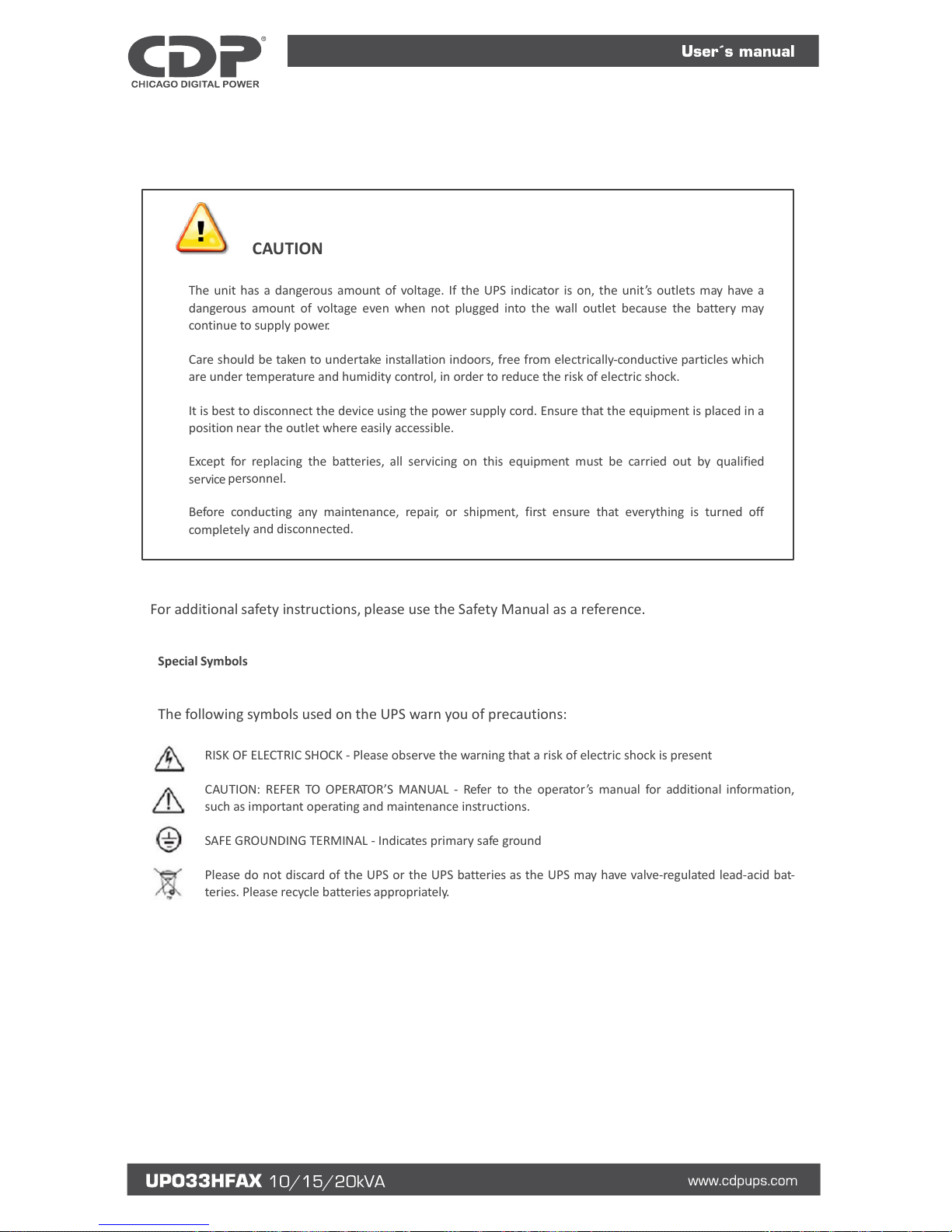
CAUTION! (UPS having Internal Batteries): Risk of electrical shock –Hazardous live parts inside this unit are
energized from the battery supply even when the input AC power is disconnected.
CAUTION! (No User serviceable Parts): Risk of electrical shock, do not remove cover. No user serviceable parts
inside. Refer servicing to qualified service personnel.
CAUTION! (Non-isolated Battery supply): Risk of electric shock, battery circuit is not isolated from AC input,
hazardous voltage may exist between battery terminals and ground. Test before touching.
WARNING! (Fuses): To reduce the risk of fire, replace only with the same type and size of fuse.
WARNING! Unit intended for installation in a controlled environment.
3

CAUTION! Do not dispose of batteries in a fire, the battery may explode.
CAUTION! Do not open or mutilate the battery, released electrolyte is harmful to the skin and eyes.
CAUTION! A battery can present a risk of electric shock and high short circuit current. The following precaution
should be observed when working on batteries:
• Remove watches, rings or other metal objects.
• Use tools with insulated handles.
To reduce the risk of electric shock, disconnect the UPS from the main supply before installing a computer inter-
face signal cable. Reconnect the power cord only after signaling interconnections have been made.
Servicing of batteries should be performed or supervised by personnel with knowledge of batteries and the
required precautions. Keep unauthorized personnel away from batteries.
For Replacement of batteries located in an SERVICE ACCESS AREA -
1) Servicing of batteries should be performed or supervised by personnel knowledgeable about batteries and
the required precautions.
2) Risk of explosion if battery is replaced by an incorrect type. When replacing batteries, replace with the
same type and number of batteries or battery packs.
3) CAUTION: Do not dispose of batteries in a fire. The batteries may explode. Dispose of used batteries
according to the instructions.
4) CAUTION –Do not open or mutilate batteries. Released electrolyte is harmful to the skin and eyes. It
may be toxic.
5) CAUTION –A battery can present a risk of electrical shock and high short circuit current. The following
precautions should be observed when working on batteries:
a. Remove watches, rings, or other metal objects.
b. Use tools with insulated handles.
c. Wear rubber gloves and boots.
d. Do not lay tools or metal parts on top of batteries.
e. Disconnect charging source prior to connecting or disconnecting battery terminals.
f. Determine if battery is inadvertently grounded. If inadvertently grounded, remove source from ground.
Contact with any part of a grounded battery can result in electrical shock. The likelihood of such shock can be
reduced if such grounds are removed during installation and maintenance.
These UPS units are extremely heavy. Caution should be taken in moving and positioning equipment. The
instructions contained within this safety manual are deemed important and should be closely followed at all times
during installation and follow-up maintenance of the UPS and batteries.
4

CAUTION
The unit has a dangerous amount of voltage. If the UPS indicator is on, the unit’s outlets may have a
dangerous amount of voltage even when not plugged into the wall outlet because the battery may
continue to supply power.
Care should be taken to undertake installation indoors, free from electrically-conductive particles which
are under temperature and humidity control, in order to reduce the risk of electric shock.
It is best to disconnect the device using the power supply cord. Ensure that the equipment is placed in a
position near the outlet where easily accessible.
Except for replacing the batteries, all servicing on this equipment must be carried out by qualified
service personnel.
Before conducting any maintenance, repair, or shipment, first ensure that everything is turned off
completely and disconnected.
For additional safety instructions, please use the Safety Manual as a reference.
Special Symbols
The following symbols used on the UPS warn you of precautions:
RISK OF ELECTRIC SHOCK - Please observe the warning that a risk of electric shock is present
CAUTION: REFER TO OPERATOR’S MANUAL - Refer to the operator’s manual for additional information,
such as important operating and maintenance instructions.
SAFE GROUNDING TERMINAL - Indicates primary safe ground
Please do not discard of the UPS or the UPS batteries as the UPS may have valve-regulated lead-acid bat-
teries. Please recycle batteries appropriately.
5

1.Main Features
1.1 Summarization
This series UPS is a kind of three-in-three-out high frequency online UPS.
The UPS can solve most of the power supply problems, such as blackout, over-voltage, under-voltage, voltage
sudden drop, oscillating of decreasing extent, high voltage pulse, voltage fluctuation, surge, inrush current,
harmonic distortion (THD), noise interference, frequency fluctuation, etc..
This UPS can be applied to different applications from computer device, automatic equipment,
communication system to industry equipment.
1.2 Functions and Features
◆3Phase In/3Phase Out UPS
It is 3Phase In/3Phase Out high-density UPS system, of which input current is kept in balance. No
unbalance problem might occur.
◆Digital Control
This series UPS is controlled by Digital Signal Processor (DSP); enhance, it increases reliability, performance,
self-protection, and self-diagnostics and so on.
◆Battery Configurable
From 16 blocks to 24 blocks, the battery voltage of this series UPS can be configured at 16 blocks, 18 blocks , 20
blocks , 22 blocks or 24 blocks according to your convenience.
◆Charging Current is configurable
Via setting tool, the user may set the capacity of the batteries as well as reasonable charging current as well
as maximum charging current. Constant voltage mode, constant current mode or floating mode can be switched
automatically and smoothly.
◆Intelligent Charging Method
The series UPS adopts advanced three-stage charging method—
1st stage: high current constant current charging
to guarantee to charge back to 90%;
2nd-stage: Constant Voltage
In order to vitalize battery and make sure batteries are fully charged
3rd stage: floating mode.
With this 3-stage charging method, it extends the life of the batteries and guarantees fast charging.
6

◆LCD Display
With LCD plus LED displays, the user may easily get UPS status and its operational parameters, such as
input/output voltage, frequency & load%, battery % and ambient temperature, etc...
◆Intelligent Monitoring Function
Via optional SNMP Card, you may remotely control and monitor the UPS.
◆EPO Function
The series UPS may be completely shut off when the EPO is pressed. REPO function (Remote EPO) is also
available in this series UPS.
1.3 System Configuration
The UPS device and the external batteries make up the system. Depending on the site and load requirements of
the installation, certain additional options are available for the solution.
Planning a UPS system, the following should be taken into consideration:
• The total demand of the protected system shall dictate the output power rating (VA). Allow a margin for
future expansion or calculation inaccuracies from measured power requirements.
• Backup time required will indicate the battery size needed. If the load is less than the UPS nominal power
rating, then actual backup time is longer.
• The following options are available:
o Connectivity Options –SNMP/WEB/Relay card
o Extended Battery Packs -Matching battery pack configuration and maximum quantity:
10kVA Maximum 4 battery packs of 80pcs/7Ah, +/- 120Vdc, 56A;
15/20kVA Maximum 4 battery packs of 80pcs/7Ah, +/- 120Vdc, 111A;
10kVA Maximum 4 battery packs of 80pcs/9Ah, +/- 120Vdc, 56A;
15/20kVA Maximum 4 battery packs of 80pcs/9Ah, +/- 120Vdc, 111A;
10kVA Maximum 1 battery packs of 300Ah, +/-96Vdc (16pcs), +/-108Vdc (18pcs), +/-120Vdc (20pcs),
+/-132Vdc (22pcs), +/-144Vdc (24pcs), 56A.
15/20kVA Maximum 1 battery packs of 300Ah, +/-96Vdc (16pcs), +/-108Vdc (18pcs), +/-120Vdc (20pcs),
+/-132Vdc (22pcs), +/-144Vdc (24pcs), 111A.
See the Specification section of this manual for additional model information.
7

2.Installation
2.1 Installation
2.1.1 Dimension (mm)
2.1.2 Installation
Leave some space around the cabinet for operation and ventilation
1. Leave at least 500mm space in the front for ventilation
2. Leave at least 500mm space at the right and left for operation
3. Leave at least 500mm space at the back for ventilation
8

2.1.3 Unpack checking
1. Don’t lean the UPS when moving it out from the packaging
2. Check the appearance to see if the UPS is damaged or not during the transportation, do not switch on the
UPS if any damage found. Please contact the dealer right away.
3. Check the accessories according to the packing list and contact the dealer in case of missing parts.
Cut off the bandage
Remove the cabinet outer package
Remove the cabinet inner package, unfasten the screws and remove the fixed wooden bar to the cabinet.
9

Place the incline board to the ground, use the screws unfastened from the last step to fasten the incline board
with pallet.
Slowly slide down the cabinet from pallet.
2.2 Cabinet Outlook
Front View Side View
10

10kVA Rear View (terminal block without cover)
(1) LCD panel
(2) Intelligent Slot 1 (SNMP card/ Relay card)
(3) Intelligent Slot 2 (SNMP card/ Relay card)
(4) Dry contact port
(5) Power Switch
(6) USB port
(7) RS485 port
(8) RS232
(9) O/P Switch
(10) Maintenance switch & its cover
(11) Bypass Switch
(12) Terminal block for Input, output & GND
(13)EPO switch
(14) REPO port
(15) Parallel port 2
(16) Parallel port 1
(17) I/P Switch
(18) Terminal block for battery
11

15-20kVA Rear View (terminal block without cover)
(1) LCD panel
(2) Intelligent Slot 1 (SNMP card/ Relay card)
(3) Intelligent Slot 2 (SNMP card/ Relay card)
(4) Dry contact port
(5) Power Switch
(6) USB port
(7) RS485 port
(8) RS232
(9) O/P Switch
(10) Maintenance switch & its cover
(11) Bypass Switch
(12) Terminal block for Input, output & GND
(13) EPO switch
(14) REPO port
(15) Parallel port 2
(16) Parallel port 1
(17) I/P Switch
(18) Terminal block for battery
12

2.3 LCD control panel
LCD control panel introduction
(1)LED(from top to bottom: “alarm”, “bypass”, “battery”, “inverter”)(2)LCD display(3)scroll button
(4)Off button (5)On button(battery cold start switch)
2.4 Installation notes
◆Please place the UPS in a clean, stable environment, avoid the vibration, dust, humidity, flammable gas and
liquid, corrosive. To avoid from high room temperature, a system of room extractor fans is recommended to be
installed. Optional air filters are available if the UPS operates in a dusty environment.
◆The environment temperature around UPS should keep in a range of 0℃~40℃. If the environment
temperature exceeds 40℃, the rated load capacity should be reduced by 12%per 5℃. The max temperature
can't be higher than 50℃.
◆If the UPS is dismantled under low temperature, it might be in a condensing condition. The UPS can't be
installed unless the internal and external of the equipment is fully dry. Otherwise, there will be in danger of
electric shock.
◆Batteries should be mounted in an environment where the temperature is within the required specs.
Temperature is a major factor in determining battery life and capacity. In a normal installation, the battery
temperature is maintained between 15°C and 25°C. Keep batteries away from heat sources or main air
ventilation area, etc.
WARNING!
Typical battery performance data are quoted for an operating temperature between
20°C and 25°C. Operating it above this range will reduce the battery life while
operation below this range will reduce the battery capacity.
◆Should the equipment not be installed immediately it must be stored in a room so as to protect it against
excessive humidity and or heat sources.
CAUTION!
An unused battery must be recharged every 6months Temporarily connecting the UPS
to a suitable AC supply mains and activating it for the time required for recharging the
batteries.
◆The highest altitude that UPS may work normally with full load is 1500 meters. The load capacity should be
reduced when this UPS is installed in place whose altitude is higher than 1500 meters, shown as the following
table:
(Load coefficient equals max load in high altitude place divided by nominal power of the UPS)
Altitude(m)
1500
2000
2500
3000
3500
4000
4500
5000
Load coefficient
100%
95%
90%
85%
80%
75%
70%
65%
13

◆The UPS cooling is depending on fan, so it should be kept in good air ventilation area. There are many
ventilation holes on the front and rear, so they should not be blocked by any exotic obstacles.
2.5 External Protective Devices
For safety reasons, it is necessary to install an external circuit breaker at the input AC utility and to the battery.
External Battery
The UPS and its associated batteries are protected against the effect of over-current through a DC compatible
thermo-magnetic circuit breaker located close to the battery.
UPS Output
Any external distribution board used for load distribution shall be fitted with protective devices so as to avoid the
risk of UPS overload.
Over-Current Protection
A protection device shall be installed at the distribution panel of the incoming utility power, and should identify
the power cables current capacity as well as the overload capacity of the system.
CAUTION!
Select a thermo-magnetic circuit-breaker with an IEC 60947-2 trip curve C (normal) for 125% of the current as
listed below.
10kVA: 50A Input Circuit Breaker required.
15kVA: 63A Input Circuit Breaker required.
20kVA: 80A Input Circuit Breaker required.
2.6 Power Cables
The cable design shall comply with the voltages and currents provided in this section, and in accordance with local
electrical codes.
WARNING!
UPON STARTING, PLEASE ENSURE THAT YOU ARE AWARE OF THE LOCATION AND OPERATION OF THE EXTERNAL
ISOLATORS WHICH ARE CONNECTED TO THE UPS INPUT/BYPASS SUPPLY OF THE UTILITY DISTRIBUTION PANEL.
CHECK TO SEE IF THESE SUPPLIES ARE ELECTRICALLY ISOLATED, AND POST ANY NECESSARY WARNING SIGNS TO
PREVENT ANY INADVERTENT OPERATION
Cable Sizes
UPS MODEL
CABLE SIZES (THHW wiring at 75°C)
AC INPUT
AC OUTPUT
DC INPUT
GROUNDING
10kVA
8 awg
8 awg
6 awg
8 awg
15kVA
6 awg
6 awg
2*6 awg
6 awg
20kVA
4 awg
4 awg
2*6 awg
4 awg
14

Recommended installed screw torque
Position
ACINPUT
ACOUTPUT
GROUNDING
Screw type
M6
M6
M6
Recommended torque(Nm)
6.5
6.5
6.5
CAUTION!
Protective earth ground cable: connect each cabinet to an earth ground, following the shortest route possible.
WARNING!
FAILURE TO FOLLOW ADEQUATE GROUNDING PROCEDURES MAY RESULT IN ELECTROMAGNETIC INTERFERENCE OR
IN HAZARDS INVOLVING ELECTRICAL SHOCK AND FIRE.
2.7 Power cable connect
Once the equipment has been finally positioned and secured, connect the power cables as described in the
following procedure.
Verify the UPS is totally isolated from its external power source and also all power isolators of the UPS are open.
Check to see if they are electrically isolated, and post any necessary warning signs to prevent their inadvertent
operation.
Open the UPS rear panel; Remove the cover of terminals for wiring easily.
2.7.1 Common input connection
15

M/1R Primary input Line
IN/OUT Input / Output
Output-L1: Output Phase L1
Input -L1: Primary input Phase L1
Output-L2: Output Phase L2
Input -L2: Primary input Phase L2
Output-L3: Output Phase L3
Input -L3: Primary input Phase L3
Output-N: Output Neutral
Input-N: Input Neutral for primary and
secondary input
GND: Grounding
BAT+: Positive terminal of the batteries string
BATN: Neutral terminal of the batteries string
BAT-: Negative terminal of the batteries string
2.7.2 Split input connection
M/1R Primary input Line
IN/OUT Input / Output
B/2R Secondary/Bypass input line (optional)
Output-L1: Output Phase L1
Mains-L1: Primary input Phase L1
Output-L2: Output Phase L2
Mains-L2: Primary input Phase L2
Output-L3: Output Phase L3
Mains-L3: Primary input Phase L3
Output-N: Output Neutral
16

Input-N: Input Neutral for primary and
secondary input
GND: Grounding
Bps-L1: Secondary input Phase L1
BAT+: Positive terminal of the batteries string
Bps-L2: Secondary input Phase L2
BATN: Neutral terminal of the batteries string
Bps-L3: Secondary input Phase L3
BAT-: Negative terminal of the batteries string
Warning!
In the case of “split bypass” operation, make sure the copper between each input
lines have been removed. The AC input and the AC bypass supplies must be
referenced to the same neutral point.
Choose appropriate power cable.(Refer to the table above)and pay attention to the diameter of the
connection terminal of the cable that should be greater than or equal to that of the connection poles;
WARNING!
If the load equipment is not ready to accept power on the arrival of the
commissioning engineer then ensure that the system output cables are safely
isolated at their ends
Connect the safety earth and any necessary bonding earth cables to the copper
earth screw located on the floor of the equipment below the power connections. All
cabinets in the UPS must be grounded properly.
CAUTION!
The earthing and neutral bonding arrangement must be in accordance with local
and national codes of practice.
17
Table of contents
Other CDP UPS manuals
Popular UPS manuals by other brands

LEGRAND
LEGRAND KEOR COMPACT Installation and user manual

Emerson
Emerson Liebert GXT4-5000RT208 user manual

Eaton
Eaton Ellipse MAX 600 Pulsar Series Installation and user manual

Eaton
Eaton Power Xpert PXGX Quick start instructions

Chloride
Chloride EDP70 User handbook

Atek
Atek Blazer Vista 400 VA user manual