Electronic Super Ducha
Instructions for installation and use
MINIMUM PRESSURE TO ALLOW
SUPER DUCHA 4 WORKING:
13 kPa/ 1,8 psi (1,3 meters of water
column height)
MAXIMUM PRESSURE TO ALLOW
SUPER DUCHA 4 WORKING:
400 kPa (40 meters of water column height)
Minimum pressure to activate the
appliance: 8 kPa/ 1psi
(0,8 meters of water column height)
Storage tank
Verify the height of the water column
from the appliance to the storage tank.
If it's greater than 5 meters keep the
pressure reducer, if it's smaller take the
pressure reducer off.
Minimum
wire
section (mm)
Circuit
breaker
(Amperes)
Maximum distance
from the circuit
breaker (m)*
4,0
10,0 50 29
Equipment
content
Volts
(V)
Nominal
power
(Watts)
127
5400
Check the product
specification
on the package
32 32220 6800
Apply sealing tape on the inlet nipple (11).
Screw the ELECTRONIC SUPER DUCHA using only your hands.
After preparing for the hydraulic installation according to Options 1 or 2,
having proceed to the hydraulic installation as follow:
1 - Pipe inlet niple (1/2 Gas thread).
2 - Support for the pipe.
3 - Pipe (30 cm).
4 - Fixing screw for the Support.
5 - Electronic temperature control:
0 0 (off) variation until maximum power.
6 - Flexible wire (electrical circuit).
7 - Electrical conductors finishing (12 cm).
8 - Wires (electrical circuit).
9 - Yellow-green wire (grounding).
10 - Electrical conductors finishing (30 cm).
11 - Water inlet niple (1/2 Gas thread).
12 -
*Water economizer “Pressure Reducer”
(verify the recommendations below)
13 - Heating chamber.
14 - Spray plate.
15 - Mark for spray plate remotion.
16 - Outlet pipe for hand shower.
17 - Cover of water outlet pipe.
18 - Hand shower and hose.
19 - Hand shower holder.
( ) Keep the pressure reducer on whenever the water pressure is
higher than 5 meters (50 kPa).
( ) Take the pressure reducer out whenever the water
pressure goes from 1,3 to 5 meters (13 to 50 kPa/ 1,8 psi).
The Electronic Super Ducha must be preferably installed at a height of 2.10 meters from the
floor to the water pipe outlet. In this way the water will not get cool during the flow.
The Electronic Super Ducha must be preferably installed at a height of 2.10 meters from the
floor to the water pipe outlet. In this way the water will not get cool during the flow.
Check if the exclusive independent electric circuit that will provide energy to the
ELECTRONIC SUPER DUCHA has the necessary minimum section, as shown
in the table below.
(*) For larger distances, contact a technician.
The Picture is not on a scale basis
When happens variation in the tension (voltage) it will also happen
variation in the temperature of the water.
Installation This product should be installed by a technician.
Sealing tape
Screwdriver
Fixed
wrench
Connector
- To connect the appliance wires to the electrical circuit, use a FAME connector or a brand of your choice.
- Never use plugs or outlets.
- On phase +neutral circuits, the phase wire should be connected to the phase and the neutral to the neutral. On phase+
phase there is not this distinction.
- Use a bipolar circuit breaker for bipolar circuits of 220 volts (F+F).
- The water resistivety at the temperature of 15° C must not be less than 1300 Ω cm. Level of protection IP-24.
- The electrical installation of FAME's Electronic Super Ducha must be done in an exclusive and independent circuit.
Before starting the hidraulic installation
Hydraulic Installation
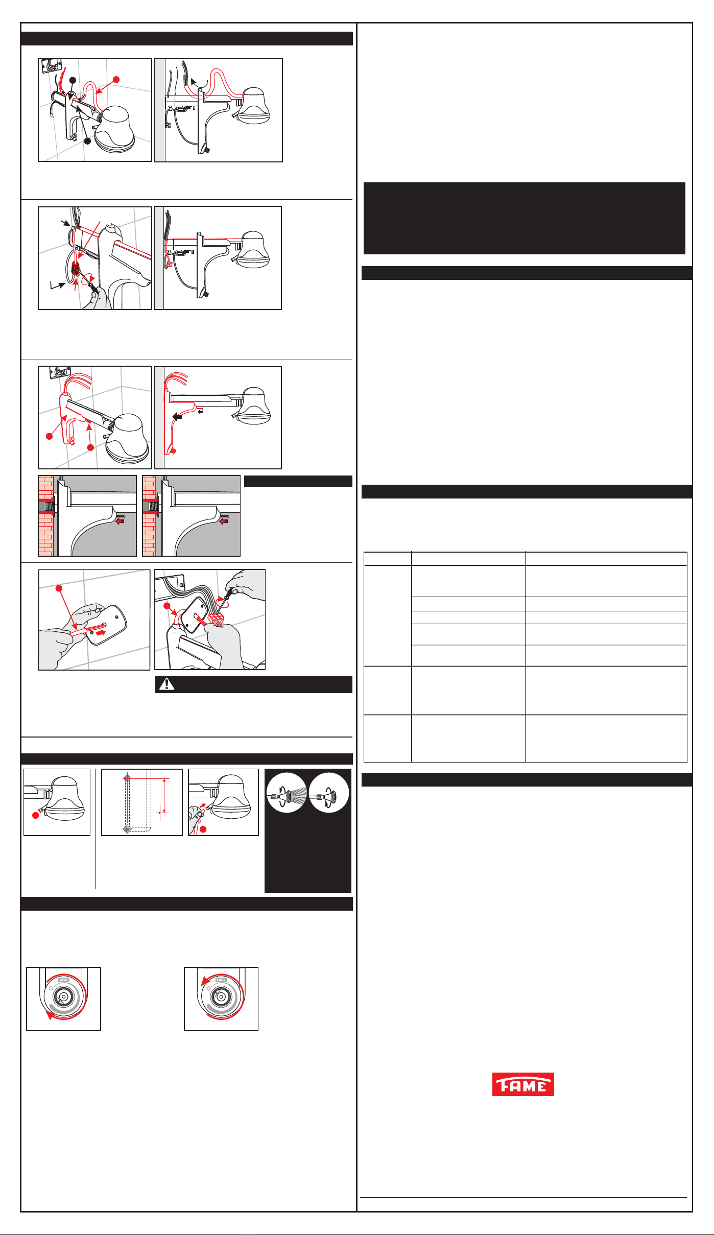
Preparing for the Hydraulic installation - Option B
OPTION B:
Preparing for the Hydraulic installation - Option A
OPTION A
Needed material:
- Connector
- Sealing tape
- Screwdriver
- Fixed wrench
These materials do not come with the product.
- Before carrying out any work ensure that the electricity supply is turned off. The tension (voltage)
of the circuit is the same of the appliance and if the wire section and the circuit breaker are in
accordance with the tag with the product features next to the bar code.
OFF
Technical features
- Clean up the water outlet pipe (C) to remove any residue.
- Ensure that the electrical circuit is turned off.
- Open the water-tap and let water flow to eliminate the residues.
- Check if the hydraulic connection diameter is ½ “ or use an adapter.
Apply sealing tape on the inlet
niple (1), screw it together with
the Support using only with
your hands, until the flange is
close to the wall (Picture 1)
Apply sealing tape in
the inlet niple (1), screw
the pipe using only
your hands, ensure
that the flange is
close to the wall
(picture 1).
Pass the Support through
the pipe to the point
shown in the Picture in
order to facilitate the
access to the wires
during the electrical
instalation.
Before proceeding this
step, ensure that the
Support is aligned to
the wall in a vertical
position (Picture 2).
Before proceeding this step,
ensure that the Support is
aligned to the wall in a vertical
position (Picture 2).
With a screwdriver loose the
screw of the Support (4), move
the screw on the pipe to the point
shown in the picture this will
enable the access to the wires
during the electrical installation.
Insert the Electronic Selector in the
Support's hole following the guides
to ensure that the Selector is
installed in the correct position.
To Put back the Selector button on the
Selector, align it to zero (0) and gently
press it.
Water
inlet niple
Pipe + SupportPipe + SupportPipe + Support
1
2
3
FLOOR
Before installing, check which option (A or B) is more suitable for
the place where your ELECTRONIC SUPER DUCHA will be installed.
Before installing, check which option (A or B) is more suitable for the place
where your ELECTRONIC SUPER DUCHA will be installed:
If the distance between the hidraulic connection and
the roof is 22cm or above, there is enough space to
screw the setting pipe + support in the hidraulic connection.
It is not necessary to separate the setting pipe + support.
If the distance between the hidraulic connection and the roof
is 22cm, there isn't enough space to screw the setting below
pipe + support in the hidraulic connection. It is necessary to
separate the setting pipe + support.
A = Electric Connection
B = Hidraulic Connection
A = Electric Connection
B = Hidraulic Connection
ROOF
13cm 16cm
2,10 m
A
B
Electronic selector
Axis of selector
Washer
Hex nut
Support
Selector button
Electronic Selector Guide
Support
Guide
FLOOR
ROOF
13cm 22cm
2,10 m
A
B
Open the water tap and let the water flow for some seconds. This operations aims to fill the heating
chamber to avoid damage to resistance and checking if there is leakage.
If there is a leakage, fix it before proceeding with the installation.
1A
1B
2B
4B
3B
2A
Flange
Flange
Water
inlet niple
Water
inlet niple
Height:
Minimum: 1,3 meters (m.c.a.)
Maximum: 40 meters (m.c.a.)
Picture 1
Picture 2
Picture 1
Electronic selector
Washer
Hex nut
Selector button Button on
position (0)
Marking (0)
Finish
Selector button
Limit Point
Checking if there is leakage
Support
Support
Shower
Pipe
Screw
Electronic
Control
Support
Screw
Axis of selector
Selector
vertical
alignment
Picture 2
Limit Point
vertical
alignment
1
1
2
2
2
11
Support
Pipe
2
3
2
3
4
4
2
3
8
9
5
4
6
7
12
13
14
15
16
17
18
19
11
10
C
ø1/2”
Product Description
To separate the pipe from the Support
proceed as follow:
With a Phillips scredriver unscrew the
Fixing screw (4) from the Support (2)
and then from the pipe (3).
Separate the electronic temperature
control from the Support:
1 - Put the temperature selector in
position (0) and pull it to remove from
the selector axis.
2 - With a Fixed wrench (10 mm) loose
the hex nut.
3 - Remove the washer.
Obs: keep these components in a
safe place not to loose them.
Observe the correct sequency of the
assembly:
1 - Insert the Electronic Selector;
2 - Insert the washer on axis;
3 - Tight the hex nut on the Electronic
Selector using a Fixed wrench
(10 mm);
4 - Put back the Selector button on it.