T.2T ZIP T.2T ZIP
32 FANANI / ASSEMBLY INSTRUCTIONS
Checking material
myShell T.2T is packed in strapped, reinforced cartons.
The following labels are applied to all cartons:
SUMMARY LABEL
- customer (Name-Surname or Company)
- order number
- model
- dimensions
-
-
- (manufacturer’s original)
- (to be left with the customer)
IMPORTANT: before unpacking check that the data on the
summary label is correct.
IMPORTANT: carton also contains the following documents
SUMMARY SCHEDULE FEATURES/DIMENSIONS
FITTING INSTRUCTIONS
MOTOR INSTRUCTIONS
USE AND MAINTENANCE MANUAL
i
i
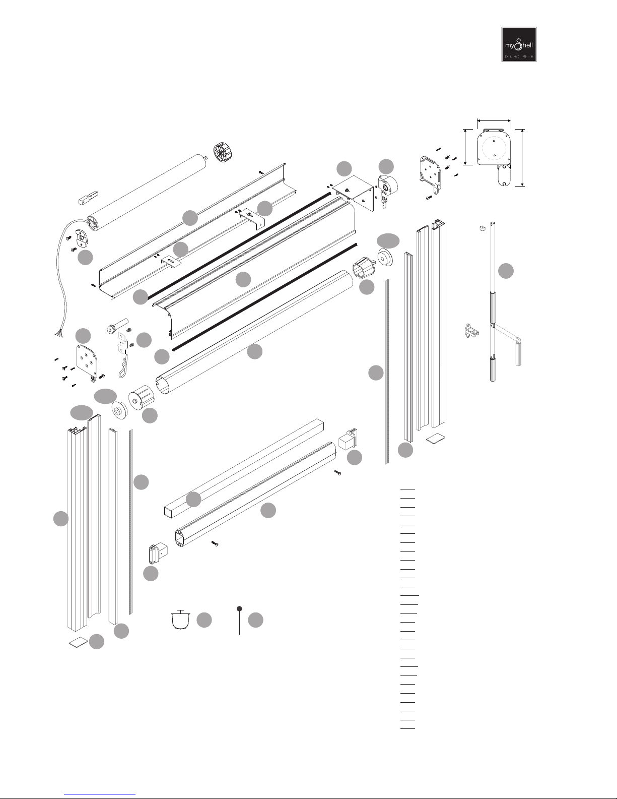
Content of the box SUPPORTS-ACCESSORIES - SCREWS:
WALL SUPPORT
SCREWS
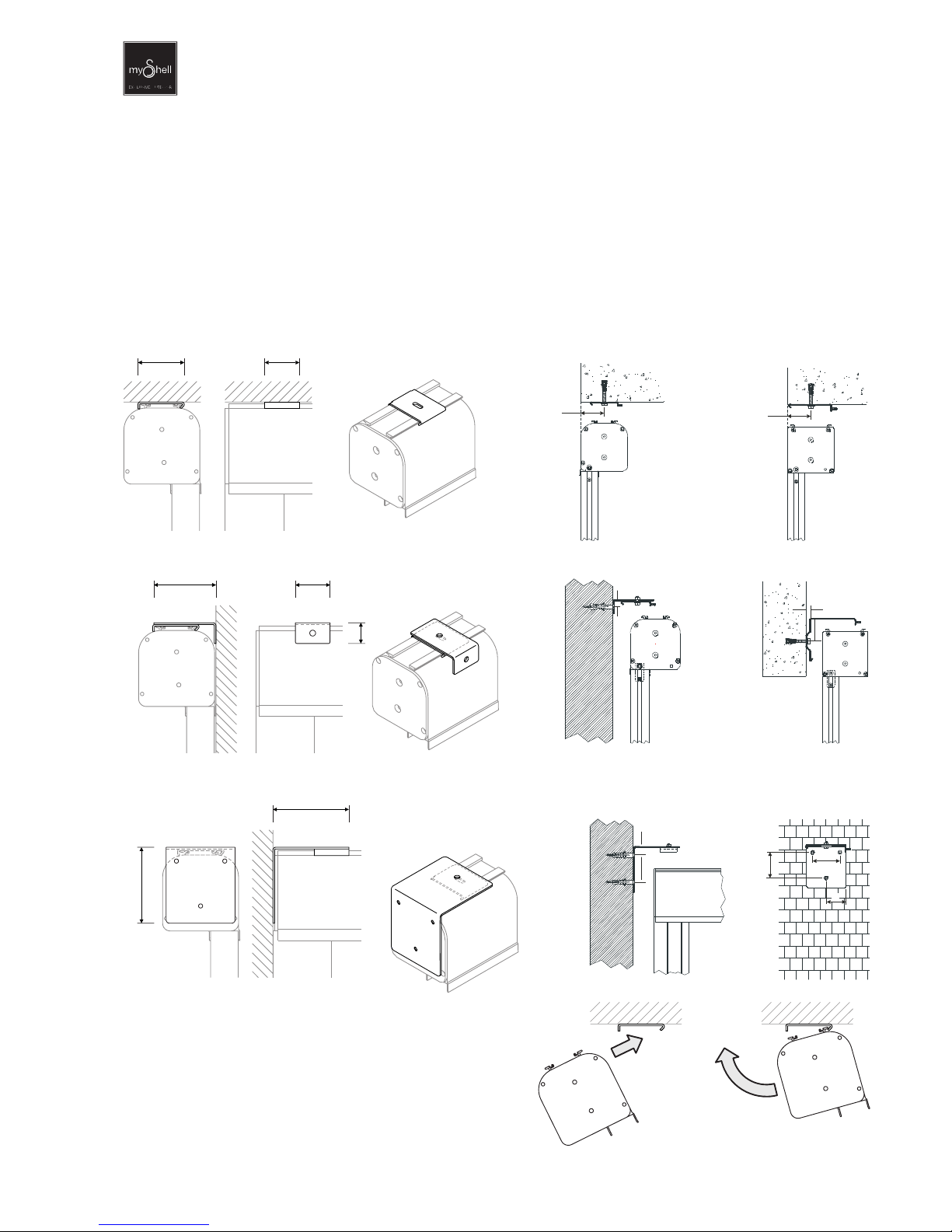
FIXING ON myShell STRUCTURES
CEILING fixing
NR 2 ceiling supports up to L. cm 230
2 stainless steel boiler-plate screws
2 self-drilling screws with varnished cylindrical head
1 rod holder + 2 self-drilling screws with varnished cylindrical head
With WINDBREAK twin tube
2 holding plates + 4 stainless steel screws with countersunk flat head
On PERLA, with front load beam and/or side beam 5x8: self-drilling screws with hex head for box and guides.
NR 3 ceiling supports up to L. cm 480
FACE fixing
NR 2 ceiling supports + counter-bracket “L” frontal up to L. cm 230
NR 3 ceiling supports + counter-bracket “L” frontal up to L. cm 480
SIDE fixing
NR 2 ceiling supports + counter-bracket “L” side
NR
NR
NR 1 brush opener (1 piece for each supply)
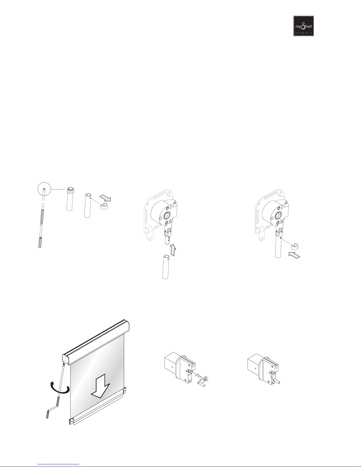
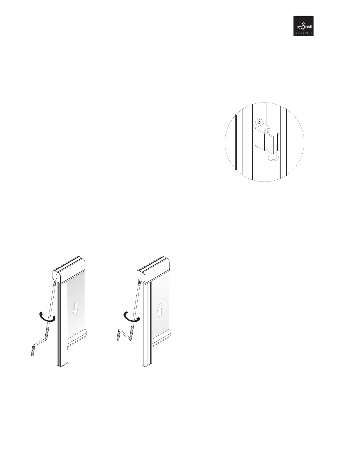
With MANUAL operation
NR
NR
On IGLOO or PERLA with front load beam and/or side beam 7x12: threaded holding plates pre-inserted into the beam and connected with
boiler plate screws.
ACCESSORIES
Others
iIMPORTANT :
screws, plugs and other fitting elements are not supplied; it is up to the installer to supply suitable
screws and supports (wall/ceiling), bases (floor mounted uprights), hardware or other suitable parts
for a safe and proper installation. The installer will certify the completed assembly by signing the
use and maintenance manual.
Roller bind
set
THIS BOX
CONTAINS
CONTENTS LABEL
Cartons: Delivery Note No.
To
Deliver to
carrier:
freight:
weight:
X/X 0000
NAME SURNAME / COMPANY
ADDRESS
POST CODE TOWN - PROVINCE
NAME SURNAME / COMPANY
ADDRESS
POST CODE TOWN - PROVINCE
SHIPPER’S NAME
CARRIAGE FORWARD
XX KG
SUMMARY LABEL
FANANI / ASSEMBLY INSTRUCTIONS
Before starting
SAFETY
The areas under the roller blind are deemed dangerous during installation. It is the installer's responsibility to
ensure that during these operations no person is wholly or partially in the danger zone. It is a good idea to display
the sign "WORK IN PROGRESS". Access the roller bind’s highest parts with suitable means in order to carry out the
installation safely. If the safety standards are complied with, no special personal protection equipment is needed.
There are no particular residual risks if not due to negligence by the operator. When working at great heights there
are risks of falling: take adequate precautions (harnesses and / or other safety devices).
PRELIMINARY CHECKS
Compare the documentation on hand (e.g. order form) to verify that the order is consistent in size and general
characteristics (structure colour, fabric colour, fastener types, optionals, etc., etc.)
PREAMBLE
Before installation is necessary to read carefully the assemby instructions attached. The mounting as the working
operations have to be execute by skilled personel only in scrupulous mode respectin the current security laws.
TRANSPORT, HANDLING, STORAGE
The roller blind is properly packed for a safe transport. In case of a not immediate mounting the package have to be
stored in a closed place with the intact package protected from hits and/or thumps and doesn’t have to be in contact
with corrosive substances. To prevent damages to components (examples : dents on the alluminuim profiles) handle
and move packages with care. If it is possible in case of manual handling of the packages the maximal weight per
person shouldn’t be more than 25 kg.
UNBOXING
At the receiving of the goods check the materials integrality. In case of anomalys do not proceed to the mounting
and inform the vendor company for the retrieval or the substitution.
INSTALLATION
It is installer’s responsability to check walls, floor or whatever else fastening support tho whom the roller blind is
settled.
The mounting is at installer’s charge qualified to release the document of THE CORRECT INSTALLATION
DECLARATION.
The electrical connections are at electrician’s charge qualified to release the document of THE CONFORMITY
DECLARATION.