manuals.online logo
Brands
  1. Home
  2. •
  3. Brands
  4. •
  5. Fancy Foam Models
  6. •
  7. Toy
  8. •
  9. Fancy Foam Models Air3dEPP006 User manual

Fancy Foam Models Air3dEPP006 User manual

Rev. 2, 10-2-2011
Fancy Foam Models, LLC
635 Laramie Cir. Maize, Ks. 67101
.fancyfoam.com
Assembly Instructions for the follo ing models:
32” Yak-55 Airfoil
32” Edge 540 Airfoil
33” Fenix V2 Airfoil
34” Freestyle Airfoil
34” MX2 Airfoil
Recommended Electronics and motors:
Motor: Turnigy 2730-1500 or any equivalent motor
Speed control: Castle Creations Thunderbird 9 or
equal.
Battery: 300 to 500, 2 or 3 cell, 20C rated or
equivalent.
Receiver: 4 channel.
Servos: (2) HXT 500 for the tail and (1) HXT 900 for
the ailerons.
Disclaimer: Fancy Foam Models has done
everything we can to caution and inform the end
user regarding the use of Lithium polymer battery
technology. We are in no way responsible for any
damage that may be caused by these batteries.
lease read, understand and follow all instructions
for the charger and batteries. Failure to use this
battery technology properly can result in the risk of
fire. If you are not comfortable with this
technology, return the batteries packs and kit to us
for a refund. By building the kit and using the
batteries, you accept full responsibility for the
safety of these batteries.
Recommended building methods and glues:
Much of the construction of this model is done by
laying the parts on a flat table. It is strongly
recommended that you put ax paper do n on the
surface first so any excess glue doesn’t soak through
the foam and glue the parts to the table. For all
assembly, use “Welders” contact adhesive. The hinges
are also done ith Welders, see our video on the eb
site. Hot glue can be used to attach the servos and
control horns.
ainting:
It is easiest to paint the parts before assembly. Card
stock can be used to make templates for stripes,
checkers, ect... Epp does is not affected much by
solvents so Krylon, Testors and airbrush paints can be
used.
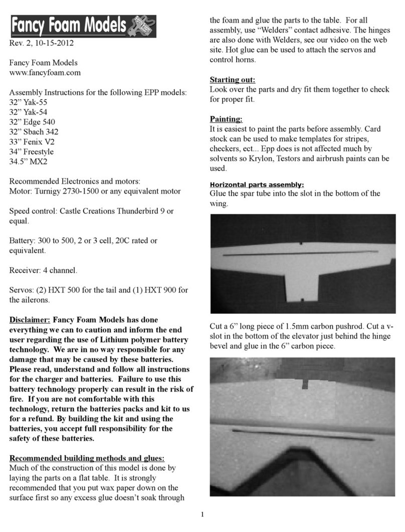
Horizontal parts assembly:
Start by gluing the ing halves together. Next, note the
marks on the ing tips and using a strait edge cut a slot
1/8” deep and 30” long centered, top and bottom of the
ing. Cut t o 30” long pieces of 1.5mm carbon rod
and press it into the slots. Sight along the leading edge
of the ing and adjust the ing so it is strait. Wick
thin CA along the top spar slot. When dry flip it over
and glue the bottom spar.
1
Cut a 6” long piece of carbon pushrod. Cut a v-slot in
the bottom of the elevator just behind the hinge bevel
and glue in the 6” carbon piece.
Hinge the ailerons to the ing and the elevator to the
horizontal stabilizer. (A Welders glue hinge
instructional video is on the eb site.)
Glue together the horizontal pieces; nose, ing, rear
fuselage and horizontal tail. Note: The ing spar goes
on the bottom and the aileron and elevator hinges go
on top.
Lower fuselage to horizontal – Assembly:
If using a stick mount, cut a slot in the horizontal nose
piece and glue the mount in place. For a fire all plate
ait until the airframe is built before installing. Set
motor mount ith NO right or do n thrust. It is not
required.
If installing a single aileron servo then cut a pocket
for it no in the nose piece. Lay the vertical pieces on
the horizontal assembly to mark and cut clearance
pockets for the aileron servo.
2
Glue the lo er vertical fuselage pieces to the
horizontal assembly making sure it is square.
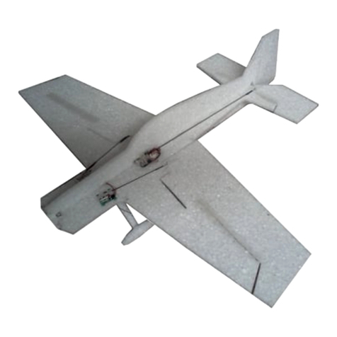
No is the time to add carbon bracing to the tail. Cut
the 1mm carbon rod into 2 – 3.5” pieces and 6 – 5.25”
pieces. Glue them per the picture ith hotglue.
(note: this step is not required on the hybrid planes
(depron/EPP))
Landing Gear reparation and Attachment:
Cut 2 pieces of the 1.5mm carbon, 8” long and t o
pieces 1” long. Glue them together as sho n ith a
1/8” overlap at a 45 degree angle. Cut a 6” piece of
string and rap the joint ith it in t o directions. CA
the string to secure the axel.
Install the gear legs through the vertical fuselage and
into the bottom of the nose but not through the nose.
When you have the axles parallel and even glue the
gear legs in place.
Glue the gear pant to the gear leg and the fuselage side.
Slide the heels onto the axels. Slide the heel pant
onto the axle and secure in place ith a drop of CA
leaving enough room for the heel to spin freely.
Upper fuselage installation:
Glue the upper fuselage in place. Cut clearance for the
aileron servo as necessary.
Hinge the rudder to the aft of the vertical fuselage
pieces.
Glue the motor stick into the slot in the nose section.
Radio installation:
We recommend using hot glue to attach the servos. The
hot glue really digs into the foam and is removable
from the plastic cases of the servos. Our models have
survived many blenders and all type maneuvers and
have never had a servo come loose.
Cut pockets and install the tail servos making sure that
the servo ires ill reach the location of the aileron
servo ires as this ill be the receiver location. The
rudder servo goes on the left side. Connect the servos
to the receiver and center them.
Use an exacto knife to slot the control horn locations in
the ailerons, elevator and rudder. Glue the horns in
place.
3
With all the surfaces set to zero, measure the distance
bet een servo arm holes and control horn holes. Cut a
piece of 1.5mm carbon rod for each push rod to the
measured lengths. Cut a 1.5” long piece of 1/32” ire
and make a z-bend on one end. Slide a pushrod guide
onto the tail pushrods before installing both ends. Slide
a 1” length of heat shrink over each end of the carbon
rod and then slide in a z-bend ire. Shrink the heat
shrink tubing ith a heat gun or flame. The z-bend
ire is not glued in position yet and can be moved for
final adjustments.
Remove the servo arm and assemble the pushrods to
the servo arm and control horns. With the servo
centered reattach the servo horn. Make any final
adjustments to the z-bend location. Use regular (not
foam safe) thin CA to secure the z-bends to the push
rods by placing a drop at each end of the heat shrink
tubing. If you get some CA on the servo or control horn
this is ok and moving the controls ill allo the z-
bend to break loose.
Motor installation
Install the motor into the stick motor mount and velcro
the speed control and receiver to the lo er left side of
the fuselage.
Flight set-up:
Use double stick Velcro on the battery and airframe to
secure the battery to the bottom of the horizontal
fuselage in a location that gives the model proper
balance. Adjust the battery location back and forth to
suit your flying style. Use your computer radio to set
the final sub-trims, exponential and dual rates. Double
check the control directions before your first flight.
With proper CG, the plane should fly nearly the
same upright or upside-down. Good pilots
experiment ith various battery locations until the CG
feels just right.
For indoor flying, e use 2 or 3 cell lipo packs rated at
20C. Batteries of 300 to 480 mah are perfect for
giving good flight times and plenty of po er. The final
airplane eight should be bet een 6.0 and 7.5 oz.
Center of Gravity:
Yak-55 is 2.75” behind the leading edge of the ing.
Edge 540 is 3.5” behind the leading edge of the ing.
Freestyle is 3” behind the leading edge of the ing.
We hope you enjoy your airplane.
Thank You,
Mike & Niki Bailey
Fancy Foam Models
4

This manual suits for next models

5

Other Fancy Foam Models Toy manuals

Fancy Foam Models Funfly003 User manual

Fancy Foam Models

Fancy Foam Models Funfly003 User manual

Fancy Foam Models 3dEPP001 User manual

Fancy Foam Models

Fancy Foam Models 3dEPP001 User manual

Fancy Foam Models IndoorDepron001 User manual

Fancy Foam Models

Fancy Foam Models IndoorDepron001 User manual

Fancy Foam Models MX2 User manual

Fancy Foam Models

Fancy Foam Models MX2 User manual

Fancy Foam Models EPP 3Decathlon User manual

Fancy Foam Models

Fancy Foam Models EPP 3Decathlon User manual

Fancy Foam Models 32” Yak-55 User manual

Fancy Foam Models

Fancy Foam Models 32” Yak-55 User manual

Popular Toy manuals by other brands

Kyosho Piper J-3 Cub M36 instruction manual

Kyosho

Kyosho Piper J-3 Cub M36 instruction manual

marklin 81845 manual

marklin

marklin 81845 manual

MTHTrains PREMIER AC6000 DIESEL ENGINE operating instructions

MTHTrains

MTHTrains PREMIER AC6000 DIESEL ENGINE operating instructions

VQ KAWASAKI Ki-61 Hien "Tony" instruction manual

VQ

VQ KAWASAKI Ki-61 Hien "Tony" instruction manual

KidzLane LASER TAG SET instructions

KidzLane

KidzLane LASER TAG SET instructions

Goldwing RC EXTRA330SC 50E manual

Goldwing RC

Goldwing RC EXTRA330SC 50E manual

REVELL KIT 5483 Assembly manual

REVELL

REVELL KIT 5483 Assembly manual

Faller Hotel Stadt Prag manual

Faller

Faller Hotel Stadt Prag manual

Enabling Devices Lonestar the Longhorn user guide

Enabling Devices

Enabling Devices Lonestar the Longhorn user guide

Hangar 9 1/5 Spitfire Mk IXc 30cc instruction manual

Hangar 9

Hangar 9 1/5 Spitfire Mk IXc 30cc instruction manual

Eduard MiG-15 Landing Flaps Assembly instructions

Eduard

Eduard MiG-15 Landing Flaps Assembly instructions

Eduard BRASSIN 648 413 manual

Eduard

Eduard BRASSIN 648 413 manual

Lionel Monopoly Hudson Steam Locomotive owner's manual

Lionel

Lionel Monopoly Hudson Steam Locomotive owner's manual

REVELL M60 A3 & M9 Raumschild Assembly manual

REVELL

REVELL M60 A3 & M9 Raumschild Assembly manual

Horizon Hobby HANGAR 9 Aermacchi MB-339 instruction manual

Horizon Hobby

Horizon Hobby HANGAR 9 Aermacchi MB-339 instruction manual

NORDIC PLAY Play Kitchen quick start guide

NORDIC PLAY

NORDIC PLAY Play Kitchen quick start guide

Ravensburger GraviTrax quick start guide

Ravensburger

Ravensburger GraviTrax quick start guide

Enabling Devices 2251 user guide

Enabling Devices

Enabling Devices 2251 user guide

manuals.online logo
manuals.online logoBrands
  • About & Mission
  • Contact us
  • Privacy Policy
  • Terms and Conditions

Copyright 2025 Manuals.Online. All Rights Reserved.