CN-ETH-485 - user manual
- 5 -
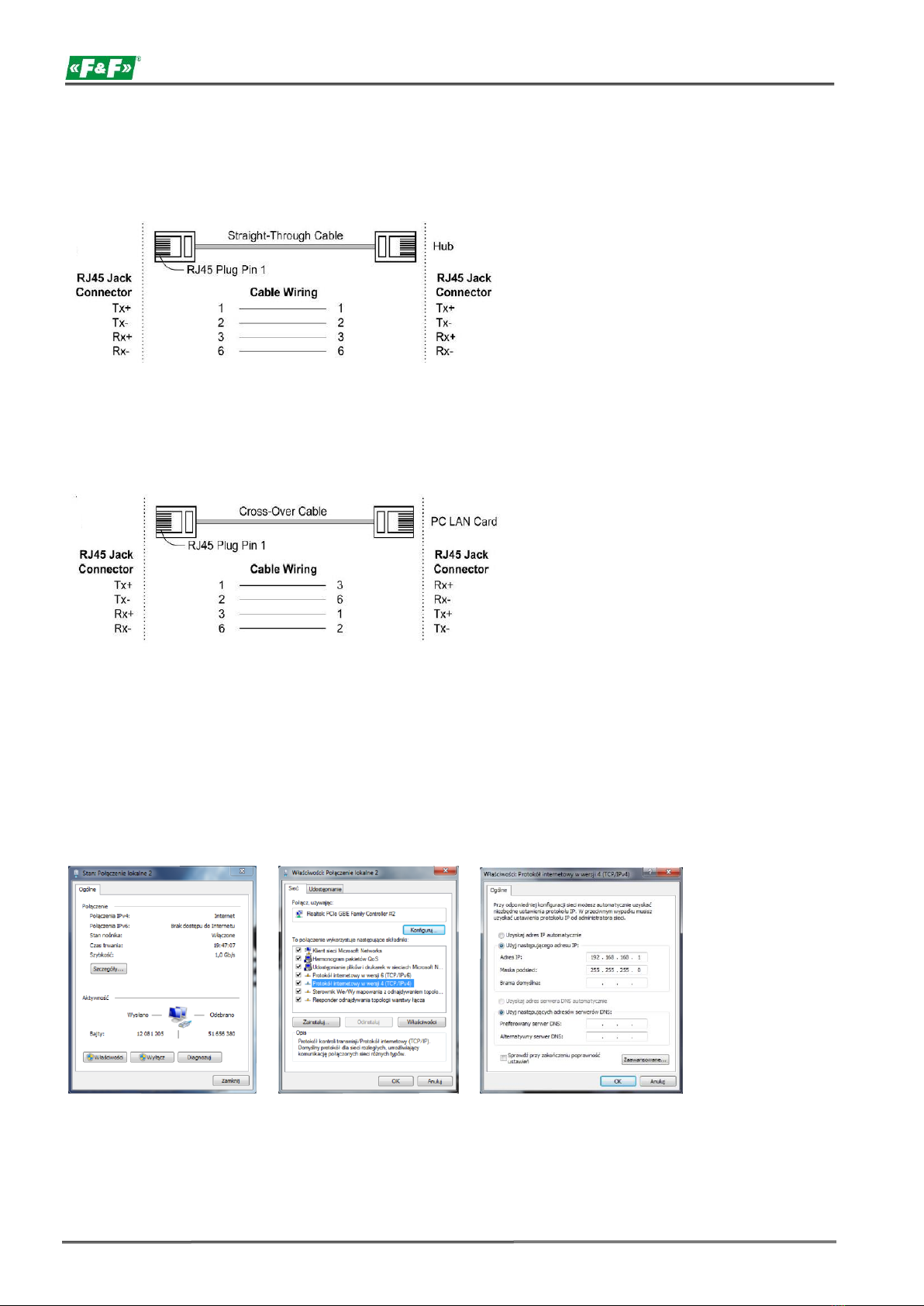
PC settings:
IP address: 192.168.2.2 to 254
Subnet mask: 255.255.255.0
IP address of the converter: 192.168.2.1
3. Open your web browser and enter the converter address
http://192.168.2.1 Accept with ENTER.
4. The login window will open. Enter the default user name and password.
User: admin Password: system
5. The converter configuration interface will open in the browser window.
CONFIGURATION
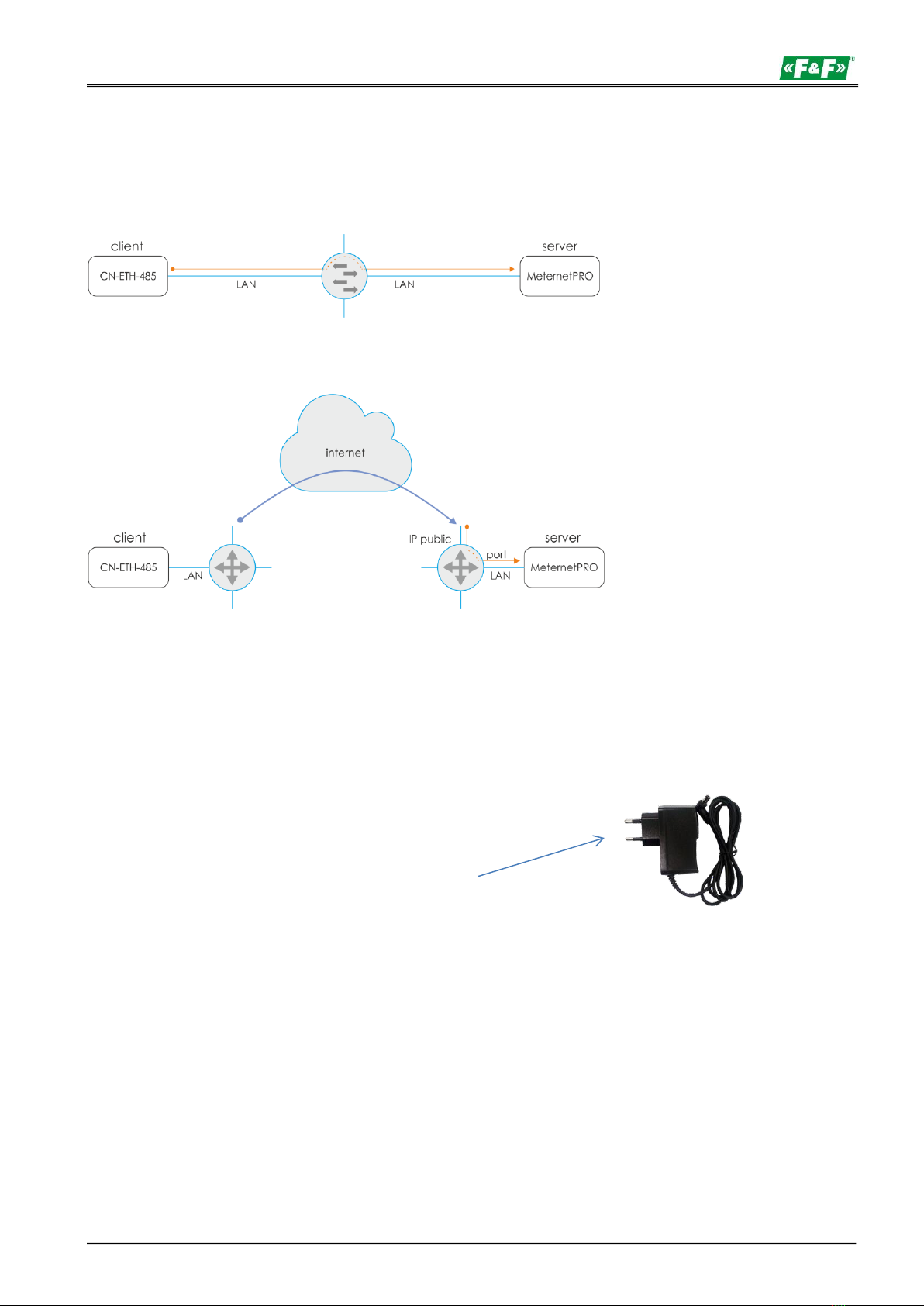
(for operation with MeternetPRO system)
Administration Setting –setting of network parameters
Nickname: - name of the device.
IP address |- setting the IP address of the local network for the converter and the parameters of the
|network in which the converter will operate.
Subnet mask Gateway | After setting a new address and saving the changes, the connection to the converter will be
terminated. New connection according to new network settings.
IP Configure - network connection mode. Select Static.
Username - user name.
Password - access password.
Update - confirmation of the changes made to the configuration.
Load Default… - return to factory settings –press Load.